M. Ouda1, K. Nigim2
1Faculty of Engineering, IUG, Gaza, Palestine
2Applied Technology, Energy & Apprenticeship, Lambton College, Sarnia, Canada
Correspondence to: K. Nigim, Applied Technology, Energy & Apprenticeship, Lambton College, Sarnia, Canada.
| Email: |  |
Copyright © 2012 Scientific & Academic Publishing. All Rights Reserved.
Abstract
Advances in two-way communication are enabled by powerful, compact and low cost antenna design that can be easily implemented in today’s compact communication devices. The paper presents a novel, compact, low profile wide bandwidth microstrip antenna array. The total size of the antenna array is 29mm x 22mm x 2mm. This new design offers a wide fractional frequency bandwidth of about 36% with a gain from 4.7dB-6.6dB over the frequency band (5GHz – 7.2GHz). The antenna design and simulation was carried out using ANSYS’ HFSS software. The application of the antenna suits many communication sensory devices and systems currently proposed for interfacing with home and industry energy harvesting devices considered to be one of the most challenging elements in building reliable smart grid infrastructure.
Keywords:
Antenna Array, Smart Grid, Wimax, Very Wide Bandwidth, Wireless Applications
Cite this paper: M. Ouda, K. Nigim, A Compact Antenna Array for Smart Grid Application, Journal of Wireless Networking and Communications, Vol. 3 No. 2, 2013, pp. 7-12. doi: 10.5923/j.jwnc.20130302.01.
1. Introduction
The electrical grid is a term used for an electricity network which is divided into three networked sectors; generation, transmission and distribution networks. Electrical energy is delivered to consumers through well connected current, carrying overhead and underground cables, transformers for voltage potential levelling, protection switchgear and power balancing equipment. The emergence of alternative means of generating electricity from renewable sources, such as wind and solar, on-site and distributed small electrical generators have forced their way into the distribution network infrastructure. To provide a high degree of flexibility in accommodating the merging distributed energy resources, the grid operator needs more information on the availability of resources and how the grid is handling the injected power.With increased data flowing across the power network, grid managers would have more warning if a demand spikes occurs and also have the opportunity to channel electricity to tied feeders before a brownout or a blackout is triggered.Likewise, the consumes would be provided with choices on what type of energy to use and when it can be consumed; consumers would be tracking their consumption in real time, possibly accepting offers to lower their electricity usage for a given period in exchange for a discount on their next bill. To enable both the grid operator, energy provider of the local utility and the consumer to share the decision making, thenetwork needs to incorporate in real time the twoways communicable devices to channel and exchange grid information. Digitizing or “smarting” the grid is, therefore, required. This does not mean that the current grid is obsolete; rather, more information exchange with the grid controlling devices needs to be communicated digitally. Successful real time information exchange with all parties in the electricity supply and demand chain provides more options for managing energy resources and provides a sustainable path for using energy. Some utilities already do the so-called demand response, where they ask companies, and even residential customers, to turn down power consumption of devices and appliances turning peak times. The smart grid, therefore, is about using real time of data to move electrical energy more efficiently and affordably. Data capturing and transmitting is then a core element in the smart grid infrastructure. Many of today’s distribution networks incorporate theSupervisory Control And Data Acquisition (SCADA) system. The SCADA system’s prime functionality is to monitor, control and provide alarms on performing network from a central location. Upgrading the existing SCADA system to play the role of smart two way information infrastructure requires strong foundation of communication between the various components of the grid and the consumer smart appliances. In many cities the utility has incorporated smart meters to collect data and speed up billing systems. A majority of these meters work in the 900 MHz bands for the links between meters and between meter and data collection units. The antenna is the basic element on these communication systems; it is a key component in system performance and size. For intelligent wireless devices to be effectively used in building the smart grid infrastructure, a robust wide bandwidth antenna is required to interface Home Area Network (HAN) with Neighbour Area Networks (NAN) devices.The most significant technology exists in bands; 2.4–2.4835 GHz and 5.15–5.825 GHz. The current fastest and most robust wireless local area networks (WLAN) operate in the 5–6 GHz band (e.g., IEEE 802.11a) which can provide reliable high-speed connectivity between notebook computers, PCs, personal organizers and other wireless digital appliances[1]. The future generation wireless networks require systems with broad-band capabilities in various environments to satisfy several applications as smart grid, personal communications, home, car, and office networking[2]. Smart grid communications, energy harvesting and data collection devices are widely available by many vendors and face several challenges [3].To overcome some of the challenges, the USA Federal Communications Commission (FCC) has issued a Report and Order (FCC 11–120) expanding the allowable licensees in the 7 GHz (6.875–7.125) and 13 GHz (12.7–13.1) bands. Therefore, the proposed design fits well in creating new opportunities across a wide array of applications that need high capacity wireless backhaul in areas where 6 and 11 GHz spectrum is not available or has insufficient capacity meeting the new FCC order.Microstrip antennas (MSA) are very popular since they allow the advantages of printed-circuit technology because of their conformal and simple planar structures.The key features of a microstrip antenna are relative ease of construction, light weight and low cost. Microstrip patch elements are available in various standard configurations such as rectangular and circular patch elements[4]. However, there are numerous shapes that were designed for the achievements of certain characteristics such as high gain and wide bandwidth. The drawbacks in MSA are its relatively low gain, efficiency and low power handling capability[5]. The design of MSA is strongly related to several characteristics, such as complexity, gain, radiation pattern, side lobe level and bandwidth. Etching the antenna array and transmission lines on the same layer enables one to reduce the manufacturing cost. Unfortunately, this may increase the size of the antenna and at the same time, could degrade the antenna performance[6]. The extensive, rapid and explosive growth in wireless communication technology and communication systems is prompting the extensive use of MSA. The tremendous growth in demand for wireless RF systems in applications such as local area networks, point-to-point communications and smart grids exploit instrumentation, scientific and medical (ISM) bands (around 5.8 GHz). The proposed antenna in this paper can be designed to be used at such frequencies. In this paper the proposed model described in the following section presents an increase of the antenna gain and power.
2. Antenna Array Model
2.1. The Antenna Structure
The proposed antenna model is shown in Fig. 1. It consists of two infinity-shaped microstrip patch antennas presented [7] fed by a Wilkinson power divider. Each patch has similar dimensions with the single patch antenna. The patches and the feeding network were printed on Roger RT/Duroid 5880TM substrate of thickness 1.57mm and εr of 2.2. The substrate has a length of 22mm and a width of 29mm. The width of the partial conducting ground plane is 29mm and the length is 10.45mm.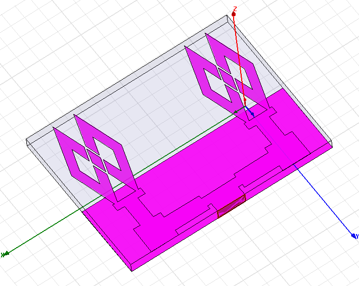 | Figure 1. Antenna geometry |
2.2. The Feed
A Wilkinson power divider is used to divide the input signal into two outputs, Fig. 2, in the field of microwave engineering. This device is capable of isolating its output ports[8] as well as preventing interference between external devices connected to these ports (e.g. antenna). Also, this is done so that mismatches and reflected signals from a port do not propagate through the system[9]. Even though this solution is quite simple, the presence of the resistor parasitic makes the design process cumbersome to a certain extent. The higher the resistivity of the resistor used, the bigger is the parasitic effect. On the other hand, use of smaller resistors in high frequency applications increases coupling between quarter - wave arms again adding to the difficulty of the design process[10].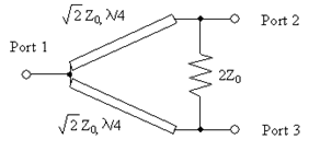 | Figure 2. Wilkinson power divider |
In the feed network, a surface mount adapter (SMA) with 50Ω connector is usually used to connect the feed line to the coaxial cable. Quarter-wave (λ/4) transformers (Z = 70 Ω) are used to match the 100 Ω lines to the 50 Ω (Zo=50 Ω) lines. All impedance dimensions for 50 Ω feedline, 70 Ω quarter-wave transformer and 100 Ω impedance line are obtained by using standard microstrip transmission line equations given in[8]. Figure 3 shows a top view of antenna array configurations with the feed dimensions.
3. Design Result and Discussion
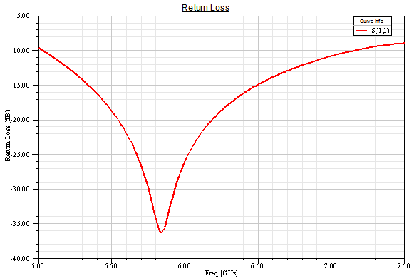
The antenna array was designed and simulated using ANSYS’ HFSS software which is the industry-standard simulation tool for 3-D full-wave electromagnetic field simulation (HFSS V12)[11].The simulated return loss (S11) for the frequency range 5GHz –7.5GHz is shown in Fig. 4. We observe that the operating frequency is at 5.8GHz with -36dB. Frequency bandwidth (BW) is defined as the range of frequencies within which the performance of the antenna, with respect to some characteristic, conforms to a specified standard. BW is usually expressed as either absolute bandwidth (ABW) or fractional bandwidth (FBW), as given by equations 1 and 2. | (1) |
 | (2) |
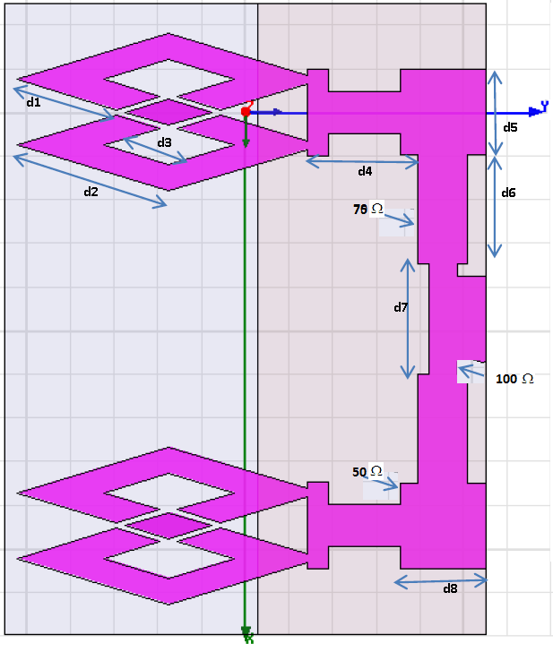 | Figure 3. Top view of antenna array configurations (d1=4.77mm, d2=7.26mm, , d3=3.1mm, d4=5.1mm, d5=3.94mm, d6=5mm, d7=5mm, d8=3.94mm.) |
 | Figure 4. The return loss vs. frequency |
The calculated ABW is 2.2GHz (5.0 GHz -7.2 GHz) which covers the required bandwidths of the 5.8 GHz WI-MAX band in addition to many other applications. Furthermore, FBW is about 36%. The VSWR for the frequency range 5GHz – 7.2GHz is shown in Fig. 5, where the bandwidth is also shown as defined by 2:1.The radiation patterns for the single element and the two elements array are simulated at the resonant frequency of 5.8GHz. The 3-D radiation pattern at this frequency is plotted and shown in Figs. 6 and 7. Here the radiation pattern of the single patch antenna is nearly omnidirectional over the operating bandwidth which is similar to the conventional monopole antenna. The simulated gain is 3dB at the 5.8GHz operating frequency. However, the radiation pattern of the two elements antenna array is more directional with higher gain, about 5.49dB at the 5.8GHz operating frequency. 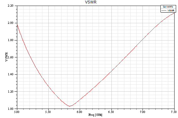 | Figure 5. The VSWR vs. Frequency |
The gain or directivity of an antenna is the ratio of the radiation intensity in a given direction to the radiation intensity averaged over all directions. Quite often directivity and gain are used interchangeably. The difference is that directivity neglects antenna losses such as dielectric, resistance, polarization, and VSWR losses. Since these losses in most classes of antennas are usually quite small, the directivity and gain will be approximately equal. The coverage area of the antenna is determined by the beam-width and the gain. The beam-width of the antenna is determined by the 3dB point that is a reduction in gain of 3dB from the maximum. The unit dB is a logarithmic unit and every 3 dB increase is a doubling of the power (intensity). This means that by increasing the gain of the antenna by 3 dB one will gain the same amount of extra range as doubling the transmitter output power. A 3 dB increment means an extended range by 1.414. This comes at a price of reducing the beam-width of the antenna.The 2D gain as a function of the elevation angle θ at the operating frequency f=5.8GHz and the horizontal angle φ=0 is shown in Fig. 8. It can be seen from the figure that the beam width is 80o. It is clear that more directive antenna has a narrower beam width and hence the coverage area of the antenna is less in width.The calculated maximum gain over the frequency range from 5GHz to 7.5GHz is shown in Fig.9. The gain of the proposed antenna is highly suitable for 5GHz to 7.2GHz wireless applications.The current distribution of the patch antenna is shown in Fig. 10. It is evident from the figure that the current distribution is not mainly confined to the edge fed microstrip line and there is some current that is fed to the radiating patch.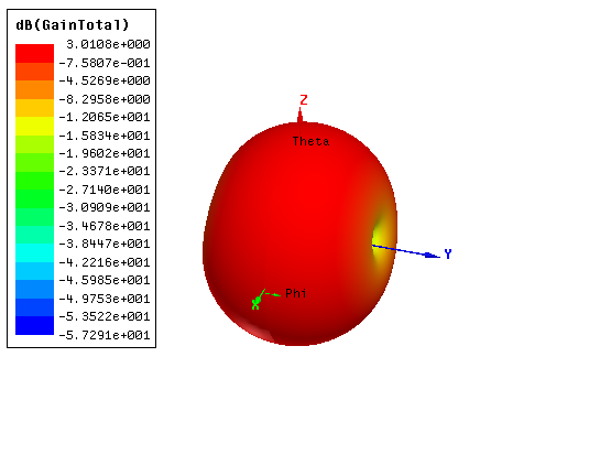 | Figure 6. The 3-D radiation pattern of single patch antenna at 5.8GHz |
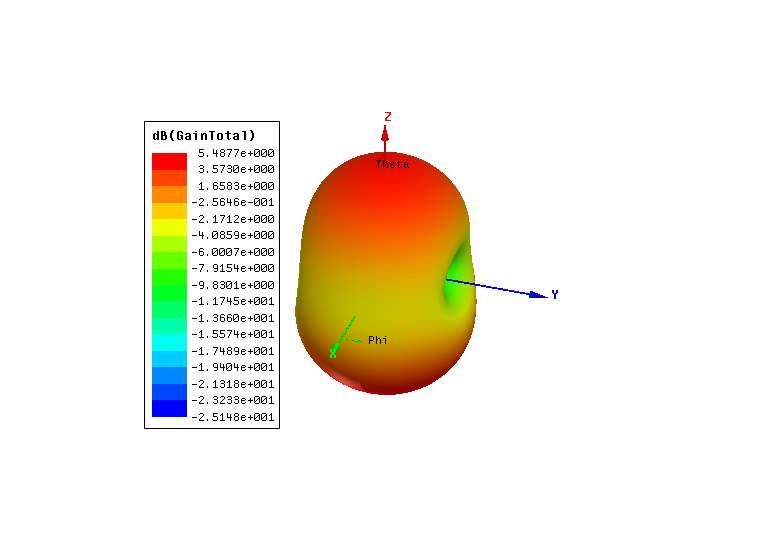 | Figure 7. The 3-D radiation pattern of two elements antenna array at 5.8GHz |
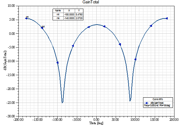 | Figure 8. The 2-D gain vs. θ of two elements antenna array at (φ=00 and f= 5.8GHz) |
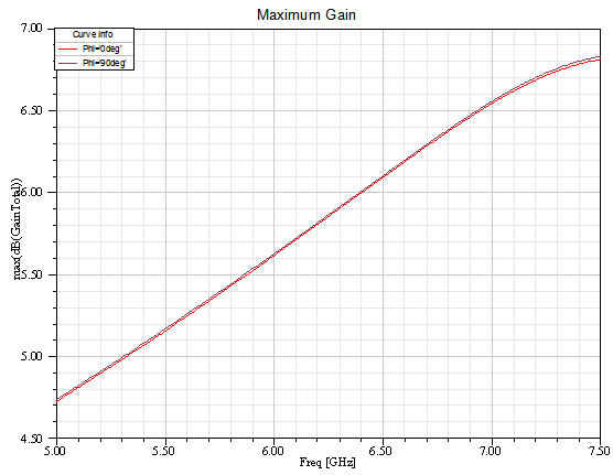 | Figure 9. Calculated maximum antenna gain vs. frequency |
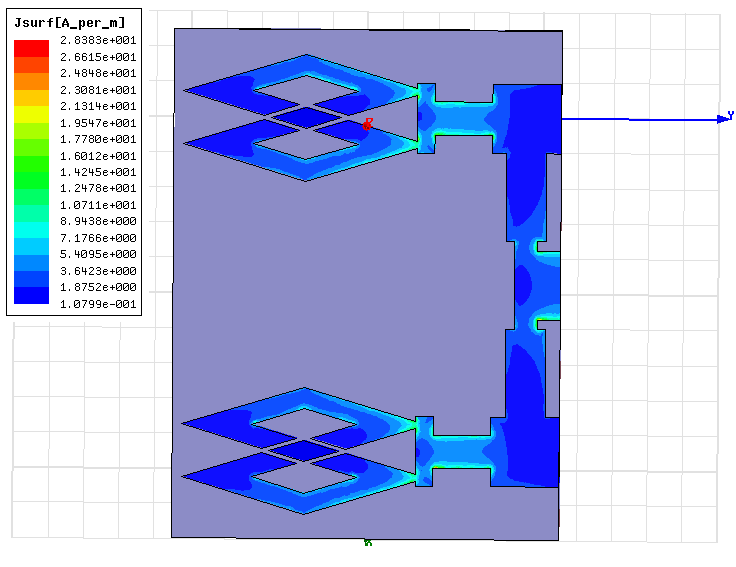 | Figure 10. Current distribution on the antenna at 5.8 GHz |
4. Conclusions
A compact low profile wide band microstrip two elements antenna array for wireless applications in 5GHz -7.2GHz frequency range has been proposed. The antenna array operating frequency lies in the bands specified for the WiMAX operation. The antenna has a bandwidth of about 36%. The gain of the antenna in the operating band is approximately 4.7-6.6dB. With the simplicity of feeding and fabrication, the proposed low profile wide bandwidth antenna array is suitable for many wireless communications in particular for interfacing smart power meters and sensory for use in smart grid application.
References
| [1] | Y. Ge, K. P. Esselle, and T. S. Bird, “E-Shaped Patch Antennas for High-Speed Wireless Networks,” IEEE Trans. Antennas Propagat., vol.52, N. 12. pp. 3213–3219, December 2004 |
| [2] | J. L. Pan, S. S. Rappaport, and P. M. Djuric, “A multibeam medium access scheme for multiple services in wireless cellular communications,” Proc. IEEE Int. Conf. Communication, vol. 3, 1999, pp. 1673–1677, 1999. |
| [3] | P. Parikh, M. Kanabar, and T. Sidhu "Opportunities and challenges of wireless communication technologies for smart grid applications," Proc. IEEE Power and Energy Society General Meeting, pp. 1-7, 2010. |
| [4] | J. R. James, P. S. Hall, and C. Wood, “Microstrip Antenna Theory and Design,”PeterPerigrinus, London, 1981. |
| [5] | L. G. Maloratsky, “Reviewing the basics of microstrip lines,”Microwave & RF. pp. 79-88, March 2000. |
| [6] | G. Leon, R. R. Boix, M. J. Freire, and F. Medina, “Characteristics of aperture coupled microstrip antennas on magnetized ferrite substrates," IEEE Transactions on Antennas and Propagation, Vol. 53, 1957-1966, 2005. |
| [7] | M. OUDA, K. Nigim; H. Reiser, “Compact wide band antenna for smart grid application,” 25th annual Canadian conference on electrical and computer engineering, PP. 1-4, April 29 – May 2, 2012, Montreal, Quebec. |
| [8] | D. M. Pozar, “Microstrip antennas," Proceedings of the IEEE, Vol. 80, 79-91, 1992. |
| [9] | C. A. Balanis, “Antenna Theory, Analysis and Design,” 3rd edition, John Wiley & Sons, New York, 2005. |
| [10] | S. Horst, R. Bairavasubramanian, Manos M. Tentzeris, and J. Papapolymerou, “Modified Wilkinson Power Dividers for Millimeter-Wave Integrated Circuits,” IEEE Trans. Microwave Theory and Techniques, vol. 55, pp. 2439–2444, Nov. 2007. |
| [11] | Ansoft Corporations, HFSS V.12- Software based on the finite element method. |
 Abstract
 Reference
 Full-Text PDF
 Full-text HTML