EL Fadl Adiba1, Anouar Dalli2, Seddik Bri1, 2, 3
1Laboratory Systems and Telecommunications Engineering Decision, Ibn tofail University, Sciences Faculty, Kenitra, Morocco
2Laboratoire d’Electronique et de Communications Ecole Mohammadia d’Ingénieurs, Université Mohammed V-Agdal Rabat, Morocco
3Materials and instrumentations group, High School of Technology: ESTM, Moulay Ismail University, Meknes, Morocco
Correspondence to: Anouar Dalli, Laboratoire d’Electronique et de Communications Ecole Mohammadia d’Ingénieurs, Université Mohammed V-Agdal Rabat, Morocco.
| Email: |  |
Copyright © 2012 Scientific & Academic Publishing. All Rights Reserved.
Abstract
Smart Antennas have recently received increasing for improving the performance of wireless radio systems. The aim of the paper is twofold. One is to design and simulate an antenna array operating in C-band (4–8 GHz) and the other is the design of beamforming algorithm used in smart antenna. In this paper, the first module presents the design of eight circular sector patch elements suitable for beamforming technique in wireless applications. The second module suggests a MP (Matrix Pencil) to accurately estimate the DOA (Direction of Arrival) of the signal of interest, and LMS algorithm for beamforming technique to concentrate the power in the desired direction and nullify the power in the interferer direction. The modelling and simulation of antenna array is computed using HFSS. The beamforming algorithm is designed in Matlab.
Keywords:
Smart Antenna, Circular Sector, Matrix Pencil, DOA, LMS
Cite this paper:
EL Fadl Adiba, Anouar Dalli, Seddik Bri, "Circular Patch Array for Smart Antenna in C-Band", Journal of Wireless Networking and Communications, Vol. 2 No. 6, 2012, pp. 175-183. doi: 10.5923/j.jwnc.20120206.03.
1. Introduction
The rising importance of wireless communication and multimedia services is increasing the efforts of design and implementation of novel microstrip patch structures from miniaturized electronic circuits to the antenna arrays[1]. The main advantages of patch antenna[2]: light weight, low cost, planar or conformal and ability of integration with electronic or signal processing circuitry. A detailed study of circular sector patch antenna is presented in[3]. This antenna has interesting dimension, so it can be integrated easily in antenna array.Recently , Smart antenna[4-5] have received increasing interest for improving the performance of wireless radio systems, their application has been suggested for mobile - communications systems, to overcome the problem of limited channel bandwidth, satisfying a growing demand for a large number of mobiles on communications channels. However Conventional Antenna systems, which employ a single antenna, radiate and receive information equally in all directions. This omnidirectional radiation leads to the distribution of energy in all directions. This Wasted power becomes a potential source of interference for other users or for other base stations in other cells. On The other hand, smart antennas consist of an antenna array, combined with signal processing in both space and time, they are capable of automatically changing the directionality of their radiation patterns in the response to their signal environment so they basically attempt to enhance thedesired signal power and suppress the interferers by beamforming toward the DOA (direction of arrival) of the desired signal and null steering in the case of the interferences. The smart antenna systems can be divided into two categories. These are: switched beam system, and adaptive arrays. In this paper adaptive arrays are investigated and used for smart antenna model.The key problem in exploiting the capabilities provided by a smart antenna at receiver is in determining the direction of the interfering signals and forming a beam towards the transmitter. The Matrix Pencil algorithm[6-9] is proposed as a super-resolution parameter estimation technique DOA. Matrix Pencil has some key advantages over the other super-resolution methods for parameter estimation, unlike other techniques, which generally need an estimation of the signal covariance matrix, Matrix Pencil deals directly with signal samples and does not require independent data samples. Furthermore, the Matrix Pencil algorithm requires less processing power and executes faster than some other super-resolution methods. One of the advantages of this technique is that the correlation among the received signals does not have a significant impact on its performances and efficiency. This paper is organized as follow: Design and simulate of circular sector patch elements are presented in section II. In section III, DOA estimation algorithm is developed. Then, the DOA algorithm supplies this information to the beamformer to orient the maximum of the radiation pattern toward the SOI (Signal Of Interest) and to reject the interference by placing nulls toward their direction, followed by the conclusion.
2. Antenna Design
2.1. Single Element Design
2.1.1. Substrate Selection
Most of the microstrip antenna research in the past has employed electrically thin, low permittivity substrates. Recent interest in millimeter wave systems and miniaturized structure[10], however, has created a need for substrates that are electrically thicker, and/or have high permittivity. Increased bandwidth is another reason for interest in electrically thicker substrates. The proposed antennas are designed using the substrate RO3210 (εr = 10.2 tanδ = 0.0035) based on Polytetrafluorel (PTFE) which is widely used because of their electrical and mechanical characteristics[2], minimum cost and permit to have a miniature antenna with a minimum loss.
2.1.2. Choice of Feeding
The most used feeding mode for patch antenna: Microstrip line, coaxial cable or proximity coupling. The feeding microstrip line and coaxial cable feed are easy to implement, however, this type of power generating spurious radiation which affects the radiation pattern. The proximity coupling offer greater bandwidth and better radiation pattern but it’s not easy to implement. In this paper we have chosen to feed our antenna via a microstrip line[10].
2.1.3. Choice of Patch
For circular sector microstrip antenna, the expression of the radius “a” of the patch is[3]:  | (1) |
kmn is the zero of the equation J '(kmn) = 0. J is the Bessel function. For the proposed design, the substrate is RO3200 (εr = 10.2), thickness h=0.127 cm. The angle and radius of circular sector patch are respectively α = 90° and a=1cm. Figure 3 shows the architecture of the proposed antenna. 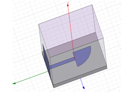 | Figure 1. Circular sector patch antenna designed in HFSS fed by microstrip line |
2.2. Array Design
A uniform array is defined by uniformly-spaced identical elements of equal magnitude with a linearly progressive phase from element to element.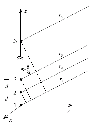 | Figure 2. Linear phased array[6] |
It is assumed that each succeeding element has a progressive phase lead current excitation relative to the preceding one. An array of identical elements with identical magnitudes and with a progressive phase is called a uniform array.The AF can be obtained by considering the individual elements as point (isotropic) sources. If the elements are of any other pattern, the total field pattern can be obtained by simply multiplying the AF by the normalized field pattern of the individual element[11].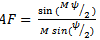 | (2) |
The function ψ is defined as the array phase function and is a function of the element spacing, phase shift, frequency and elevation angle: 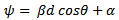 | (3) |
Where β=2π/λ is the phase propagation factor.Studied array will be designed using HFSS. The software enables to compute antenna array radiation patterns and antenna parameters. HFSS models the array radiation pattern by applying an “array factor” to the single element’s pattern[12]. Figure 3 present studied arrays with an inter-element distance of 0.6λ and number of element is 4 and 8.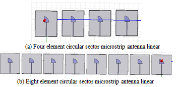 | Figure 3. Proposed antenna arrays |
2.3. Simulation of Single Element and Array
2.3.1. Return Loss
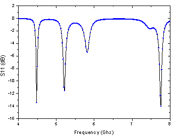 | Figure 4. Return loss of rectangular and circular sector microstrip antenna in C-band |
Figure 4 shows the return loss simulated for proposed circular sector microstrip antenna. This antenna resonates at three frequencies: 4.48 GHz, 5.27 GHz and 7.8 GHz with return loss between -12 dB and -14 dB. So we can say that proposed antenna exploit well the C-band. For array of 4 and 8 elements, we got the same curve of single element. So changing number of element didn’t impact return loss of antenna.
2.3.2. Radiation Pattern
The radiation pattern of an antenna is important in determining most of the characteristics which include beamdwidth, beam shape, directivity and radiated power. Radiation pattern is computed using HFSS. So in this section, we trace radiation pattern for single element, array of 4 and 8 elements.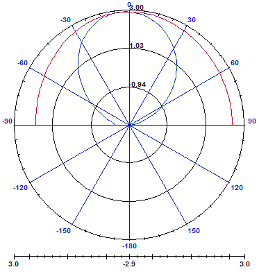 | Figure 5. Radiation pattern of circular sector antenna at 4.48Ghz |
In figure 5, we traced radiation pattern in E-plan of circular sector antenna. Main lobe is directive and there is no secondary lobe.Figure 6, shows radiation pattern of 4 array element. The main lobe is more directive than single element pattern, but there is more secondary lobe.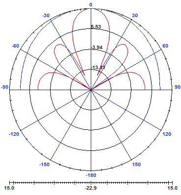 | Figure 6. Radiation pattern of 4 element array |
Then we trace radiation pattern of 8 element array: | Figure 7. Radiation pattern of 8 element array |
It can be observed clearly that the beam widths of all major lobes became narrow and the number of minor lobes increases, when the number of element increases.
2.3.3. Directivity and Gain
The directivity is a measure of the directional properties of an antenna compared to the isotropic antenna. The gain of the antenna directly depends on the radiation efficiency and the directivity of the antenna[11]. The table 1 shows generated gain and directivity for circular sector antenna array for different number of elements (M = 1; 4; 8).| Table 1. Gain and directivity for circular sector microstrip antenna array for M = 1; 4; 8 |
| | Number of elements | Gain (dB) | Directivity (dB) | | 1 | 5 | 5.13 | | 4 | 10 | 10.74 | | 8 | 12.11 | 12.47 |
|
|
For array with larger the number of elements, the total gain and directivity increase. But we cannot increase number of element to infinite number, it’s important to take in consideration the dimension of array[13].
3. Smart Antenna
A smart antenna is an antenna array system aided by some smart algorithm designed to adapt to different signal environments. A smart antenna is an antenna system that can modify its beam pattern or other parameters, by means of internal feedback control while the antenna system is operating. The basic idea behind smart antennas is that multiple antennas processed simultaneously allow static or dynamical spatial processing with fixed antenna topology. The pattern of the antenna in its totality is now depending partly on its geometry but even more on the processing of the signals of the antennas individually. Several algorithms have been developed based on different criteria to compute the complex weights[14-15].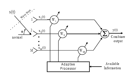 | Figure 8. Smart antenna architecture |
As illustrated in the figure 8, the smart antenna consists of M antenna elements separated from each other by a known distance d, and receives N signals. Let’s define the array signal vector by: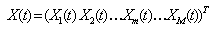 | (4) |
The incoming signal vector by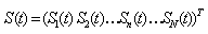 | (5) |
The noise vector by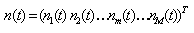 | (6) |
Where n(t) is a with a zero mean Gaussian white noise. is the steering vector of the array expressing its complex response to a planar wavefront arriving from direction
  . The array response vector
  is given by:
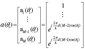 | (7) |
Now if we consider all sources simultaneously, the signal at the mth element will be: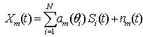 | (8) |
And array factor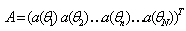 | (9) |
We can now write in matrix notation: | (10) |
Let’s denote the weights of the beamformer as: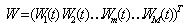 | (11) |
Where W is called the array weight vector. The total array output will be: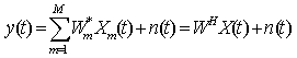 | (12) |
Where superscripts T and H, respectively, denote the transpose and complex conjugate transpose of a vector or matrix.
3.1. DOA Estimation
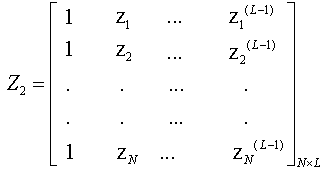
In this paper, we use Matrix Pencil to determinate DOA of signals impinging on smart antenna.Consider the following  matrix formed using data from equation (11):
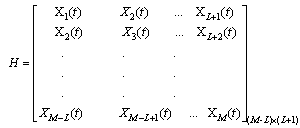 | (13) |
Where L is called the pencil parameter. Now we define two  matrices H1 and H2 as:
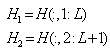 | (14) |
These two matrices can be written as: | (15) |
Where: | (16) |
Where 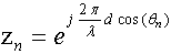
 | (17) |
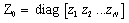 | (18) |
 | (19) |
Our goal is to estimate the entries of the matrix Z0.Consider the following matrix pencil, | (20) |
Here I is the (dxd) identity matrix.The estimates of zi are, therefore, the generalized eigenvalues of the matrix pair[Y1,Y2] .Once the values of zi are estimated, we can estimate DOA: | (21) |
Where Im[ zi] is the imaginary part of zi.
3.2. Adaptive Beamforming
Using the information supplied by the DOA, the adaptive algorithm computes the appropriate complex weights to direct the maximum radiation of the antenna pattern toward the SOI and places nulls toward interferes. The adaptive beamforming algorithm chosen in this project is the LMS for its low complexity[16-17]. The LMS algorithm is an approximation of the steepest descent method using an estimator of the gradient instead of the actual value of the gradient. This simplifies considerably the calculations to perform and allows the LMS algorithm to be performed in real time. Based on the array geometry of Figure 8, the signal received by the array is given by: | (22) |
The error is given by: | (23) |
The expression for weight updating: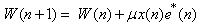 | (24) |
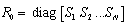
μ is a step size parameter which is related to the rate of convergence; however, convergence of the w(n) is assured by the following condition: | (25) |
Where λmax is the largest eigenvalue of autocorrelation matrix Rxx of received signal.
3.3. Results Simulations
The simulated system consists of an eight linear arrangement of circular sector antenna array spaced by distance d = 0.6 λ. The received signal arrives at an angle of 50 degrees, interferers arrives at 25 and 80 degrees, the SNR=20 dB. After the antenna array receives all the signals from all directions, the DOA algorithm determines the directions of all impinged signals on antenna array as shown in table 2. Then an adaptive array is simulated in Matlab by using the LMS algorithm. The true array output y(n) is converging to the desired signal d(n). The interferers are cancelled by placing nulls in the direction of the interferers. We have chosen step size = 0,01 for our simulation. After the calculating weights in Matlab simulation we apply the normalized weights as excitations in the designed antenna array. The resulting antenna array gain pattern is shown in Figure 9 for three frequencies F1=4.48 GHz, F2=5.27 GHz and F3=7.8GHz using Matlab.| Table 2. DOA estimation using Matrix Pencil |
| | Frequencies (GHz) | Estimated DOA of desired signal (degree) | Estimated DOA of the first interfere (degree) | Estimated DOA of the second interfere (degree) | | 4.48 | 49.98 | 25.08 | 80 | | 5.27 | 49.98 | 25 | 79.99 | | 7.8 | 50 | 24.99 | 79.99 |
|
|
From Table 2, Matrix Pencil can accuracy estimate DOA of signals impinging on array antenna with SNR=20 dB for the three frequencies.Figure 9 gives good results for three frequencies, the main beam is centred on the direction of desired DOA, the side lobes are at least -30 dB below the main beam and Zeros are all below -100 dB.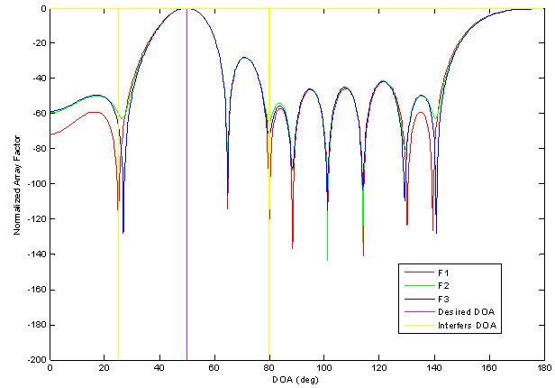 | Figure 9. Array factor plot for three frequencies |
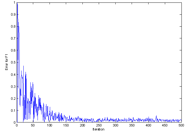 | Figure 10. Error plot for LMS algorithm for F1 |
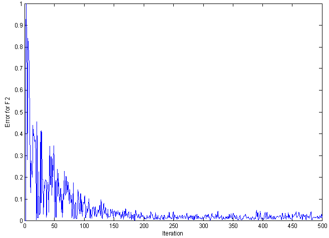 | Figure 11. Error plot for LMS algorithm for F2 |
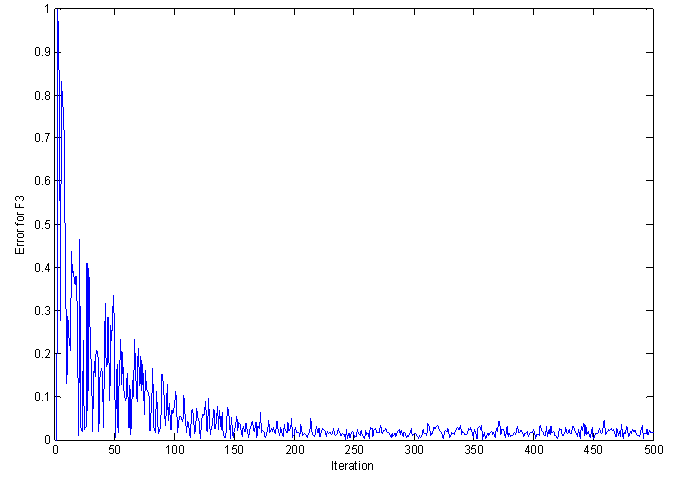 | Figure 12. Error plot for LMS algorithm for F3 |
Figures 10-13 show the error between the output and the reference signal over 500 iterations for three frequencies, the error decreases much faster, consequently the convergence is reached after about 50 iterations, and the final error is very low. 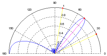 | Figure 13. Polar plot for F1 |
 | Figure 14. Polar plot for F2 |
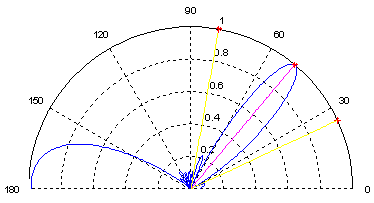
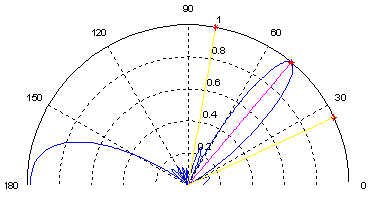 | Figure 15. Polar plot for F3 |
Figures 13-15 show that Smart Antenna directs the main beam towards the desired signal and eliminates interferers by forming nulls in there directions. Notice that all figures give very close results for the three frequencies.
4. Conclusions
In this paper, we have presented an antenna array operating in C-band (4–8 GHz), which consists of eight circular sector patch elements. This antenna array has advantage to resonate at three frequencies: 4.48 GHz, 5.27GHz and 7.8 GHz. The design of this antenna was studied and simulated using HFSS. DOA of desired and interferes signals was accurately estimated by Matrix Pencil method. After LMS algorithm was applied to direct the main beam towards the desired signal and form nulls in the directions of interferes, consequently simulations demonstrate that this antenna is feasible for integration on smart antenna systems.
References
| [1] | S.Bellofiore, J.Foutz, R.Govindarajula, ˙I.Bahçeci, C. A. Balanis, A.S. Spanias, J.M. Capon , and T.M. Duman” Smart Antenna System Analysis, Integration and Performance for Mobile Ad-Hoc Networks (MANETs)” IEEE Transactions On Antennas And Propagation, Vol. 50 No. 5, pp 571-581, May 2002 |
| [2] | D.M.Pozar “Microstrip Antennas” Proceeding of the IEEE, Vol. 80 No 1, pp 235-244, January 1992 |
| [3] | A.Dalli, L.Zenkouar and S.Bri “Study of Circular Sector Patch Array Antenna With Two and Four Elements for C and X Band” European Journal of Scientific Research Vol.81 No.2, pp.150-159, 2012 |
| [4] | J.C. Liberti, Jr and T.S. Rappaport "Smart Antennas for wireless communications: IS-95 and Third Generation CDMA Applications" Upper Saddle River, NJ: Prentice Hall PTR. 1999 |
| [5] | T.K. Sarkar, M.C. Wiks, M. Salasar, and R.J.Bonneau, "Smart Antennas", IEEE press Wiley - interscience. USA, 2003 |
| [6] | Y.Hua and T.K.Sarkar "Matrix pencil method for estimating parameters of exponentially damped/undamped sinusoids in noise” IEEE Transactions On Antennas And Propagation, Vol.38 No5, pp. 814-824, May 1990 |
| [7] | Y.Hua and T.K. Sarkar "Matrix pencil method and system poles", Signal Processing Vol.21 No 2, pp. 195-198, October 1990 |
| [8] | Y.Hua and T.K.Sarkar “On SVD for estimating generalized eigenvalues of singular matrix pencil in noise,” IEEE Transactions on signal processing, Vol.39 No. 4, pp 892-900 April 1991. |
| [9] | J.E.Río and T.K.Sarkar, “Comparison between the matrix pencil method and the Fourier transform technique for high-resolution spectralestimation,” Digital signal processing, Vol. 6 No.4 pp.108-125, April 1996 |
| [10] | D.H.Schaubert, D.M.Pozar, A.Adrian “Effect of Microstrip Antenna Substrate Thickness and Permittivity: Comparison of Theories with experiment” IEEE Transactions on Antennas and Propagation, Vol. 31 No. 6, pp 83-90, June 1989 |
| [11] | C.A. Balanis “Antenna Thoery:Analysis and Design” New York : Wiley 1997 |
| [12] | Online documentation of HFSS on: www.ansys.com |
| [13] | V.R.Anitha and N.Reddy “Design of an 8x1 square microstrip patch antenna array” International Journal of electronic engineering research Vol .1 No.1 pp 71-77 (2009) |
| [14] | F.Debbat et F.T.Bendimerad “Les Algorithmes d’Optimisation Globale: Application Réseaux Intelligents d’Antennes“ SETIT 2005 3rd International Conference: Sciences of Electronic, Technologies of Information and Telecommunications,TUNISIA March 27-31, 2005 |
| [15] | S.F. Shaukat, M.Hassan, R.Farooq, U.Saeed and Z.Saleem “Sequential Studies of Beamforming Algorithms for Smart Antenna Systems” World Applied Sciences Journal Vol.6 No.6, pp 754-758, 2009 |
| [16] | B.Widrow, P.E.Mantey, L.J.Grifiths and B.Goode, “Adaptive antemna systems” Procedung IEEE, Vol.55 No.12 pp2143-2159, December 1967 |
| [17] | A.ELfadl, S.Bri, M.Habibi, “Multipath Elimination using Matrix Pencil for Smart Antenna with Uniform Linear Array”, European Journal of Scientific Research Vol. 87 No 3 pp.397-405, October 2012. |
 Abstract
 Reference
 Full-Text PDF
 Full-Text HTML