Rakesh Kumar Yadav 1, Sushrut Das 1, R. L. Yadava 2
1Department of Electronics Engineering, Indian School of Mines (ISM), Dhanbad, 826004, India
2Department of ECE, Galgotias College of Engineering & Technology, Gr. Noida, 201306, India
Correspondence to: Rakesh Kumar Yadav , Department of Electronics Engineering, Indian School of Mines (ISM), Dhanbad, 826004, India.
| Email: |  |
Copyright © 2012 Scientific & Academic Publishing. All Rights Reserved.
Abstract
This paper presents Ansoft HFSS based parametric analysis and design of UWB bicone antenna. The design frequency of proposed antenna is 2.4 GHz. This antenna covers the 1.3 ~ 17.5 GHz frequency band with Return loss less than -10 dB. The bandwidth has been achieved by making a simple and easy modification in the design parameter of the bicone antenna. The voltage standing wave ratio (VSWR) less than 2 within the frequency range of 1.3 GHz ~ 17.5 GHz of this antenna is noticed. This antenna can be used in S (2 GHz to 4 GHz), C (4 GHz to 8 GHz), ext. C (3.4 GHz to 6.725 GHz) and X (8 GHz to 12 GHz) band frequencies and all three frequency band of industrial, scientific and medical (ISM), which are reserved internationally for the use of radio frequency (RF) energy for purposes other than communications. Examples of applications in these bands include radio-frequency process heating, microwave ovens, and medical diathermy machines.
Keywords:
Radiation Pattern, Biconical Antenna, Ultra Wide Band, VSWR and Transverse Electromagnetic (TEM).
Cite this paper:
Rakesh Kumar Yadav , Sushrut Das , R. L. Yadava , "Parametric Study of UWB Biconical Antenna for Wide-band Applications", Journal of Wireless Networking and Communications, Vol. 2 No. 5, 2012, pp. 117-125. doi: 10.5923/j.jwnc.20120205.06.
1. Introduction
Wireless communication is the fastest growing field of communication technology which has captured the attention of social life in the present scenario. For the successful implementation of any wireless communication system, the antenna technology plays one of the important roles. A proper design of the antennas can reduce the system requirements and improve the overall system performance. An overview of the frequency band allocated for modern wireless communication standards are summarized in Table 1. Ultra Wideband (UWB) is an emerging technology for future short-range wireless communications with high data rates as well as radar and geolocation. A landmark patent in UWB communications was submitted by Ross in 1973. However, it was in 1989 that the term “Ultra Wideband” appeared in a publication of department of defence in the United States (U.S.) and the first patent with the exact phrase “UWB antenna” was filed on behalf of Hughes in 1993. To guarantee the coexistence of UWB with other communication standards, the authorized transmitted power is always very low which limits the development of UWB communication systems with very high data rates and/or the coverage of larger distances. The association of Multiple Input Multiple Outputs (MIMO) systems (which exploit rich scattering environments by the use of multiple antennas) with UWB technology is more and more studied.It seems to be a very potential approach for enhancing capacity, increasing range, raising link reliability and improving interference cancellation. There are two criteria available to identify an antenna to be considered as an Ultra| Table 1. Frequency band allocations |
| | System | Description | Frequency Band | | DVB-H | Digital Video Broadcasting | 470-890 MHz | | GSM-900 | Global System for mobile communication | 880-960 MHz | | GPS | Global Position Systems | 1227.60 MHz1575.42 MHz | | DCS-1800 | Digital Communication System | 1710-1795 MHz | | PHS | Personal Handy-Phone Systems | 1905-1920 MHz | | PCS-1900 | Personal Communication System | 1850-1990 MHz | | UMTS | Universal Mobile Telecommunications Systems | 1920-2170 MHz | | Wi-Bro | Wireless Broadband | 2300-2390 MHz | | RFID | Radio Frequency Identification Systems | 30 – 2400 MHz | | ISM | Industrial, Scientific and Medical | 2400-2484 MHz5150-5350 MHz5725-5825 MHz | | UWB | Ultra Wide Band | 3100 -10600 MHz |
|
|
Wide Band (UWB) antenna. One definition requires a UWB antenna to have a fractional BW greater than 0.25 [1]. An alternate and more recent definition places the limit at 0.2 [2]. That is given by equation 1:  | (1) |
Where  is the upper end frequency and
  is lower end frequency of the antenna operational band. There are three classes of UWB antennas based on their applications. a. First is the "DC- to- Daylight" class having the maximal bandwidth.b. Second is the "multinarrow band" class- receiving or detecting narrowband signals across broad swaths of frequencies. c. Third the "modern" UWB antennas- having 3: 1 bandwidth. A modern UWB antenna must be well behaved and consistent across the operation bandwidth of antenna [3].
2. Biconical Antenna
A biconical antenna consists of an arrangement of two conical conductors, which is driven by potential, charge, or an alternating magnetic field at the vertex. The conductors have a common axis and vertex. The two cones face in opposite directions. Biconical antennas are broadband dipole antennas, typically exhibiting a bandwidth of 3 octaves or more.Further, when the wireless systems that are potential candidates for cognitive radio are considered, UWB seems to be one of the tempting choices because it has an inherent potential to fulfil some of the key requirements of cognitive radio. These requirements include no spurious interference to licensed systems, adjustable pulse shape, bandwidth, transmitted power, support of various throughputs, provision of adaptive multiple access, and security of information. However, it is not claimed that a cognitive wireless system using only the UWB technology can handle all the requirements of an ideal cognitive radio. Advances in reconfigurability of RF front-ends, particularly reconfigurable antennas, afford a new “hardware” dimension for optimizing the performance of wireless communication systems. Recent development in communication, surveillance and Electronics Support Measurer (ESM) demands antennas with very wide bandwidth and omni radiation pattern. Broadband antenna has received much attention for application in wireless communication systems, listed in Table 1. Several Antennas have already been reported [4], to suit the above mentioned requirement. Among these antennas, one of the most useful omnidirectional antennas is the biconical horn [5]-[6].Antenna engineers discovered that, starting from a dipole or monopole antenna, thickening the arms results in an increased bandwidth. Thus, for a thick dipole or monopole antenna, the current distribution is no longer sinusoidal and where this phenomenon hardly affects the radiation pattern of the antenna, therefore this strongly influences the input impedance too. This band widening effect is even more severe if the thick dipole takes the shape of a biconical antenna. The biconical antenna evolved towards a single cone which presents a limited well matched impedance bandwidth but a stable phase centre within the bandwidth. Another evolution of the biconical antenna is the bow-tie antenna, the flat version of the biconical antenna. Several techniques have also been proposed to improve the antenna bandwidth, for example, the use of a bevelling plate, a double feed or an asymmetrical feed arrangement, a trident-shaped feeding strip etc. However, they are not planar structures because their ground planes are perpendicular to the radiators. This drawback limits their practical applications due to their large area. Biconical antenna was first introduced by Schelkunoff [7]. In theory, both the input impedance and radiation pattern of infinite biconical antenna have nothing to do with the frequency characteristics, As regards to finite biconical antenna, both the input impedance and radiation pattern change as the frequency changes. A biconical antenna is used in a system that requires 360 degree coverage in the azimuthal plane with a particular coverage in the elevation plane [8]. Due to the frequency independent nature of its construction, the biconical antenna is well-suited for use in ultra – wide band systems. The biconical antenna, consisting of two linear cones, excited symmetrically at the apices [9].In Year 2003, J. D. Morrow proposed a biconical antenna which covers the frequency range of 3.1 GHz to 10.6 GHz [10]. Latter D.N. Black, Jr. and T.A. Brunasso developed a high impedance bicone antenna covering 25 MHz to 6 GHz [11]. However in 2009, Z. Hou, W. Li, W. Jian and Ma Laixuan proposed a new bicone antenna for EMC test application, which found to be suitable in frequency range of 500 MHz to 2.5 GHz, and I. Gronich developed a bicone antenna with asymmetric cones covering the frequency band of 2 GHz to 18 GHz [12, 13]. In 2010, Y. Huichun and G. Yougang developed an anti-interference bicone antenna useful for wireless communication application in the frequency range of 0.85 GHz to 2.5 GHz [14]. Recently, S. Zahirah Sapuan, A. Kazemipour, M. Zarar and M. Jenu developed a bicone antenna suitable to be used as calibration antenna in the frequency band of 200 MHz to 2 GHz [15].Biconical (or "Bicon") antenna is a broadband radiator, however its poor efficiency at low frequencies, results in low field strengths when compared to the input power. It may behave either an omnidirectional or directional antenna if it is kept vertical or horizontal respectively. The impedance of the feeding point of biconical antenna is usually chosen to be 50 Ω, however when the vertical angle of the conical geometry is enlarged, impedance becomes small. And it becomes a dipole aerial if vertical angle reduces it to the utmost limit, and the impedance range is found to be about 73Ω to 50Ω. Hence the Biconical antennas are often used in electromagnetic interference (EMI) testing either for immunity testing, or emissions testing from 25-200 MHz (Commercial specifications) or 30-200 MHz (Military applications).
3. The Proposed Bicone Antenna
Biconical antennas were originally intended for use over the frequency range 20 MHz to 200 MHz. The first designs had a poor return loss, typically less than 4 dB over most of the frequency range. The antenna shown in Figure 1 is composed of two symmetric cone-like structures. The design parameter like outer and inner radius of the cone are 10cm and 0.51cm respectively, while the height of the cone is 6.5cm.There is a port between the two cone whose gap is 0.5cm and width is also 0.5cm. The return loss versus frequency curve corresponding to this antenna are plotted in Figure 2.The antenna is able to direct the beam in horizontal direction. In present research a biconical antenna is developed with symmetric conical discs. The antenna is simulated with Ansoft HFSS simulator. The antenna is matched over a very large bandwidth (1.3GHz to 17.5GHz). Antenna performances are generally altered by the change in design structures. We optimize the performances by changing the design parameters. Figure 3, Figure 4 and Figure 5 shows the optimization considering cone inner radius, while Figure 6 to Figure 9 shows optimization with cone outer radius. Optimization with cone height is shown in Figure 10, Figure 11 and Figure 12. Port gap and port width optimization are shown in Figure 13 to Figure 15. The results of optimized biconical antenna are shown in Figure 16, Figure 17 and Figure 18. Table 2 shows the optimized parameter of a bicone antenna. | Figure 1. Geometry of Bicone Antenna |
| Table 2. Optimized parameters of Bicone Antennas |
| | Parameters | Dimensions | | Cone Inner Radius | 0.39 cm | | Cone Outer Radius | 9.0 cm | | Cone height | 5.5 cm | | Port Gap | 0.3 cm | | Port Width | 0.5 cm | | Bandwidth | 1.3 GHz to 17.5 GHz | | VSWR | Less than 2 | | Fractional BW | 1.72 |
|
|
 | Figure 3. Return loss Vs frequency for cone inner radius of 0.31, 0.41, 0.51, 0.61, and 0.71 (cm) |
 | Figure 4. Return loss Vs frequency for cone inner radius of 0.39, 0.40, 0. 41, 0.42, 0.43 and 0.51(cm) |
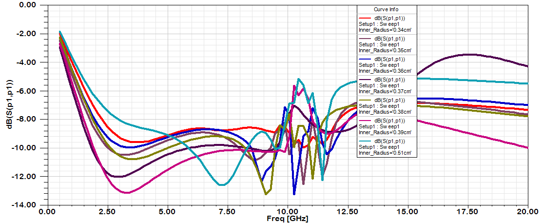 | Figure 5. Return loss Vs frequency for cone inner radius of 0.34, 0.35, 0.36, 0.37, 0.38, 0.39 and 0.51(cm) |
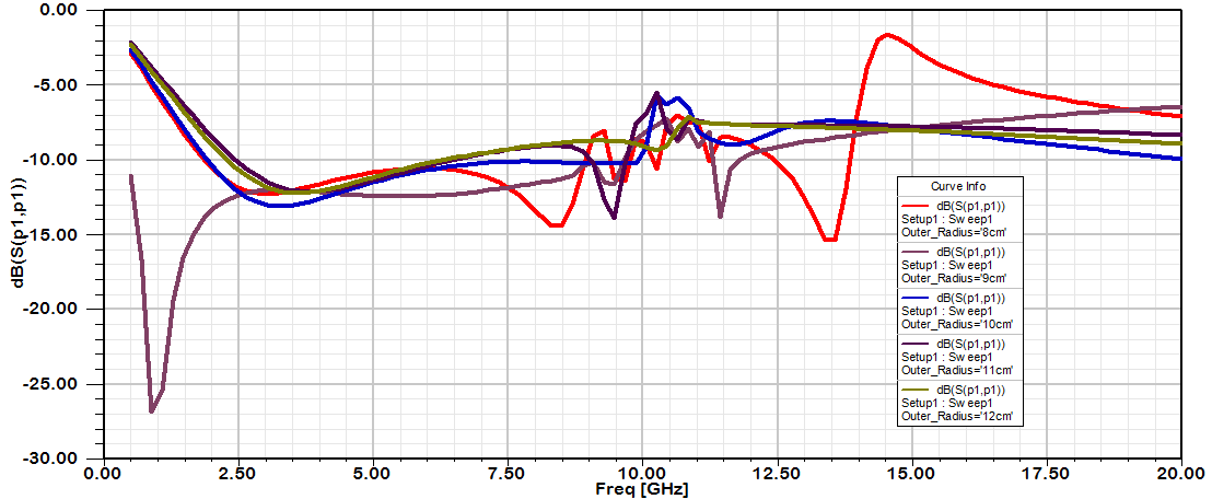 | Figure 6. Return loss Vs frequency for cone outer radius of 8, 9, 10, 11 and 12 (cm) |
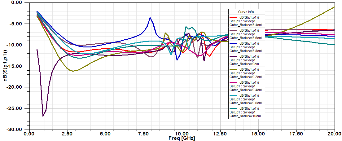 | Figure 7. Return loss Vs frequency for cone outer radius of 8.4, 8.6, 8.8, 9.0, 9.2, 9.4, 9.6 and 10 (cm) |
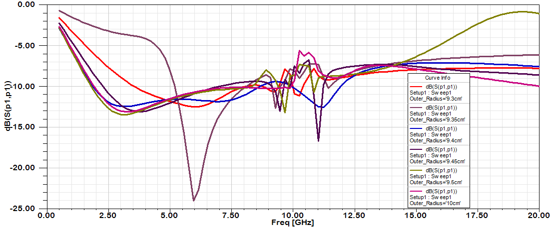 | Figure 8. Return loss Vs frequency for cone outer radius of 9.3, 9.35, 9.4, 9.45, 9.5 and 10 (cm) |
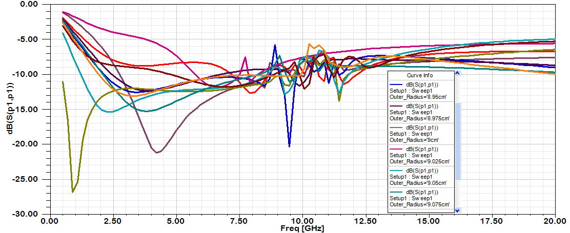 | Figure 9. Return loss Vs frequency for cone outer radius of 8.95, 8.975, 9, 9.025, 9.050, 9.075, 9.1 and 10 (cm) |
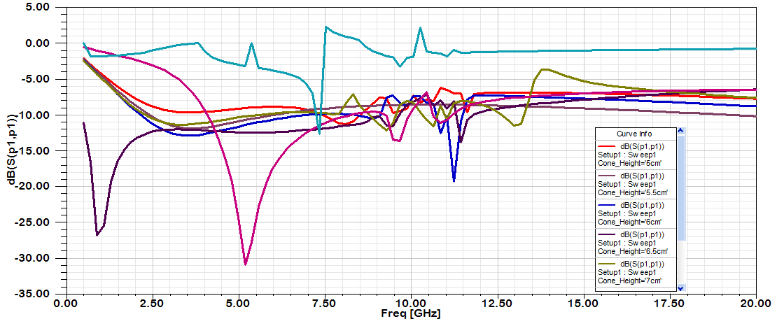 | Figure 10. Return loss Vs frequency for cone height of 5, 5.5, 6, 6.5, 7, 7.5 and 8 (cm) |
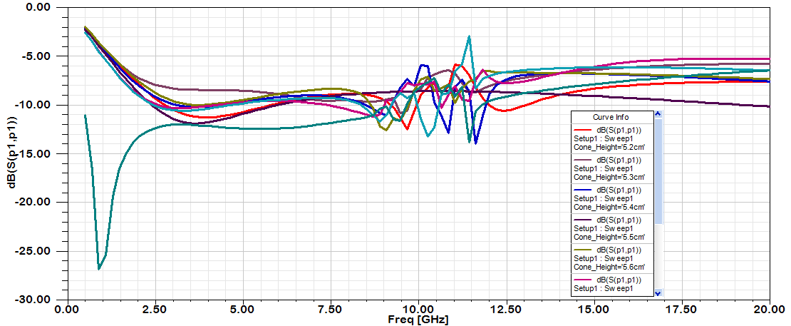 | Figure 11. Return loss Vs frequency for cone height of 5.2, 5.3, 5.4, 5.5, 5.6, 5.7, 5.8 and 6.5 (cm) |
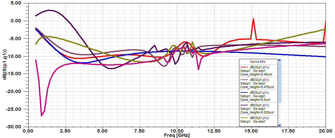 | Figure 12. Return loss Vs frequency for cone height of 5.45, 5.475, 5.5, 5.525, 5.5 and 6.5 (cm) |
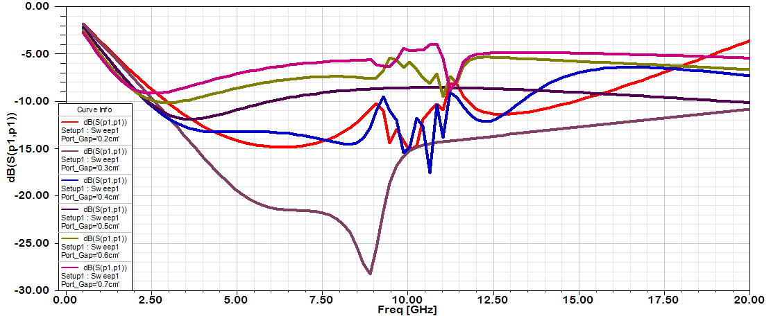 | Figure 13. Return loss Vs frequency for port gap of 0.2, 0.3, 0.4, 0.5, 0.6 and 0.7 (cm) |
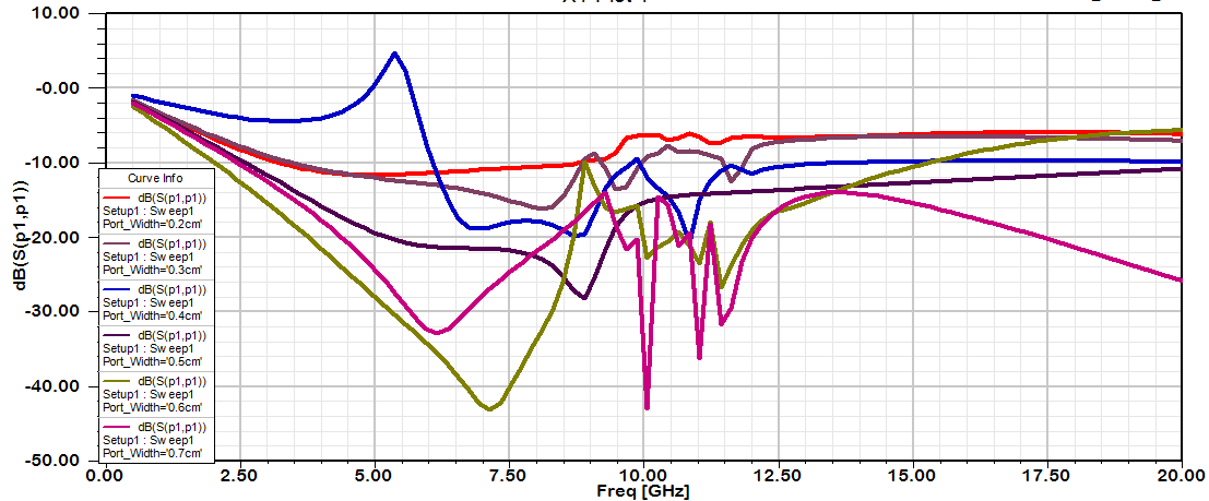 | Figure 14. Return loss Vs frequency for port width of 0.2, 0.3, 0.4, 0.5, 0.6 and 0.7 (cm) |
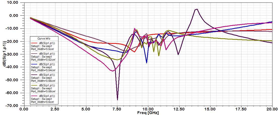 | Figure 15. Return loss Vs frequency for port width of 0.5, 0.52, 0.54, 0.56, 0.58 and 0.6 (cm) |
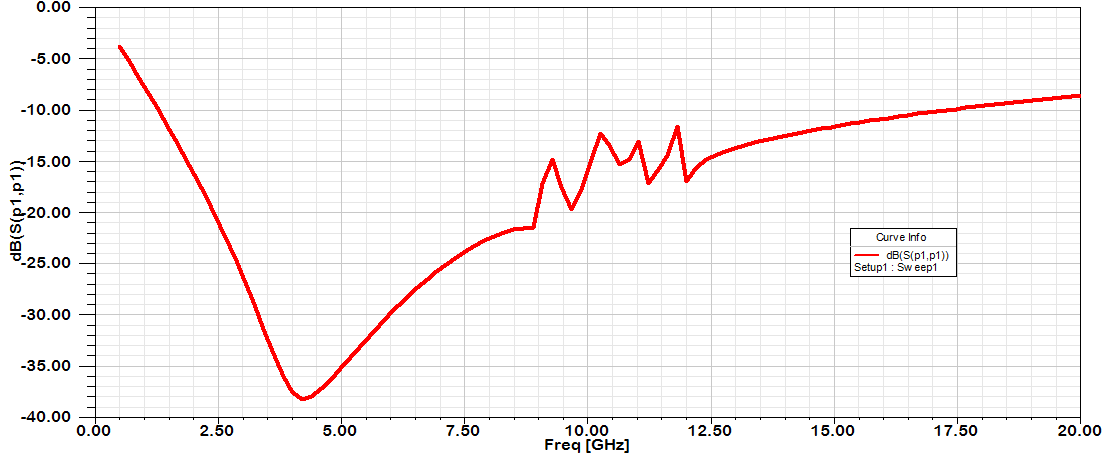 | Figure 16. Optimized Return loss Vs frequency of proposed Bicone Antenna |
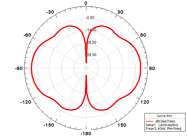 | Figure 17. Optimized Radiation Pattern of proposed Bicone Antenna |
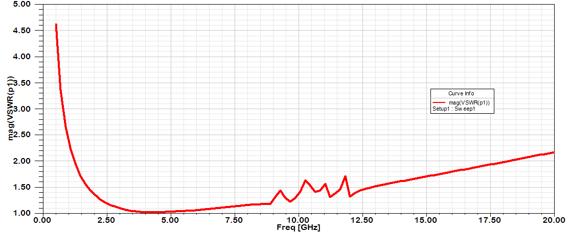 | Figure 18. VSWR of proposed Bicone Antenna |
4. Conclusions
In this paper, a novel broadband biconical antenna with symmetric conical discs suitable for wireless communication systems is designed. The results of this antenna are impressive due to its improved bandwidth (1.3 GHz-17.5 GHz) having Return loss < -10 dB and VSWR < 2. However available literatures indicate that no such bicone antennas having this much BW was proposed earlier [10-15]. If a bicone transmits to a receiving TEM horn, then the induced current in the horn will be exactly identical to the driving-point voltage of the bicone. Such observations can have very important ramifications in broadband high-speed information transmission. The broadband characteristics of the biconical antenna make it a good choice for making sweep measurements and for automated measurement systems. It is also used in electromagnetic interference (EMI) testing either for immunity testing, or emissions testing.
ACKNOWLEDGEMENTS
The author is deeply indebted to the guidance and help of Dr. B. K. Kanaujia, Associate Professor, Ambedkar Institute of Technology, Delhi.
References
| [1] | Foster, Charles, et al., "Assessment of Ultra-Wide Band (UWB) Technology," IEEE Aerospace and Electronic Systems Magazine, November, , pp. 45-49, 1990. |
| [2] | U.S. 47 C.F.R. PART15 Subpart F&15.530d Ultra wide band operation (October 1, 2003 edition), p.767, 2003. |
| [3] | Hens Schantz, Ultra Wide Band antennas, Artech House, Boston! London, pp. 31-32, 2005. |
| [4] | Chih-Ming SV and Kinslu Wong, "Narrow flat plate antenna for 2.4 GHz WLAN operation," Electron. Lett, vo1.39, No: 4, pp. 344-345, 2003. |
| [5] | J.D. Kraus, Antennas, Mc Graw- Hill Book Company, New York, pp.217-229., 2006. |
| [6] | H. Jasik, Antenna Engg. Handbook, 1st ed., Mc Graw Hill Book Company, New York, pp. 3-10, 3-13, 1961. |
| [7] | Schelkunoff S., Advanced Antenna Theory. N J: D. Van Nostrand, Princeton, 1952. |
| [8] | D. Ghosh, T. K. Sarkar and E. L. Mokole,” Design of a wide-Angle Biconical Antenna for Wide Band Communications,” Progress in Electromagnetics Research B, Vol.16, 29-245, 2009. |
| [9] | Oleksiv S. Kim, “A Compact Biconical Antenna with Improved Radiation pattern,” Union Radio Scientifique Internationale (URSI) -2008. |
| [10] | Janett D. Morrow, “Shorted Biconical Antenna for Ultra-Wideband Application”, in Proc. of IEEE Symp. pp. 143–146, 2003. |
| [11] | Donald N. Black, Jr. and Theresa A. Brunasso, “An Ultra – Wide Band Bicone Antenna”, in Proc. of IEEE Symp. pp. 327–332, 2006. |
| [12] | Zhang Hou, Li Weimin, Wang Jian and Ma Laixuan,“ A Novel Small Sized Biconical Broadband Antenna for EMC Test Application ” , 2009. |
| [13] | I. Gronich, “Omni directional ultra wideband asymmetric biconical antenna”, 2009. |
| [14] | Yang Huichun and Gao Yougang, “Research on non-omnidirenctional Biconical Broadband Antenna”, IEEE, pp. 520-521, 2010. |
| [15] | Syarfa Zahirah Sapuan, Alireza Kazemipour, Mohd Zarar and Mohd Jenu, “Direct Feed Biconical Antenna as a Reference Antenna”, IEEE International RF and Microwave Conference, pp. 5- 8, 2011. |
 Abstract
 Reference
 Full-Text PDF
 Full-Text HTML