Ezmerina Kotobelli , Renalda Kushe
Department of Electronic Engineering and Telecommunications, Faculty of Information Technology Polytechnic University of Tirana, ALBANIA
Correspondence to: Ezmerina Kotobelli , Department of Electronic Engineering and Telecommunications, Faculty of Information Technology Polytechnic University of Tirana, ALBANIA.
| Email: |  |
Copyright © 2012 Scientific & Academic Publishing. All Rights Reserved.
Abstract
Nowadays, wireless services are becoming increasingly present in our daily lives. UMTS technology is successfully implemented and is already installed everywhere. Wi-Fi service should be tested to coexist with UMTS service, with minimal interference. Hence in typical domestic environments is verified the possibility of coexistence of two antennas, in the same access space. Initially, the characteristic of Wi-Fi antennas parameters are measured. Then we measured the effect of positioning the two antennas in vicinity, in different configurations. Results of measurements show that the configuration of the access point can determine the pair of antennas that provides better appearance in terms of adaptation and topology of the installation.
Keywords:
Antenna, Wi-Fi, UMTS, Access Space, Measurement
Cite this paper:
Ezmerina Kotobelli , Renalda Kushe , "The Study of Interference between UMTS and Wi-Fi in Indoor Environments", Journal of Wireless Networking and Communications, Vol. 2 No. 5, 2012, pp. 95-100. doi: 10.5923/j.jwnc.20120205.03.
1. Introduction
Wall construction and the presence of various furnishings substantially affect the propagation of the electromagnetic field in indoor environment[1][2][3]. Design of Wi-Fi networks in such environments requires the simultaneous review of other parameters such as the type of environment, type of antenna, its position in relation to the axis and the receiver antenna.Various researchers have worked hard in this area and have issued general diffusion models for indoor environment through simulations[4][5]. Recently has been taken in consideration the impact of the presence of different technologies in the same access space[6][7].We are interested to study interferences of Wi-Fi network from UMTS technology[8] because today's trends are to be present both of these services, in the same access space.The S antennas parameters[9] are directly affected by this interference. Therefore, the measurement model is defined based on these parameters. The section two describes some analysis of Wi-Fi coverage in different indoor environments. In section three S antennas parameters and measurement setup are described. The results of measurements are given in section four. In this section the characteristic parameters of Wi-Fi antennas are measured. Then we have seen the effect of positioning the two antennas in the vicinity, for a typical distance of the access point, in different configurations. In the fifth section some discussions are made, about results expectations. In last section are given some conclusions and suggestions for the antenna couple that gives the best performance, which is the antenna couple that guarantees the smallest rate of match between the two antennas.
2. Analysis of Wi-Fi coverage in indoor environments
In this session will be briefly described a measurement study performed over Wi-Fi antennas operating in the band 2.4 - 2.5 GHz in topology of various indoor environments[10]. Typical settings are chosen to represent different behaviors of electromagnetic waves in various indoor environments such as brick walls, gypsum walls as well as special areas of internal environment consisting of one side entirely glass window.
2.1. Determination of Measurement Conditions
Bank of measurements consists on transmission block and receiver block. Transmission block consists on a signal generator or synthesizer (HP 8340°), a signal amplifier itself (PRANA AP32TW125) and transmitting antennas. PRANA AP32TW125 amplifier, after generated signal earlier in radio frequencies, intended to lead to a power transmitting antenna such that provides a significant coverage in the environment. For this transmission are being used three antennas on Wi-Fi band (2.4-2.5 GHz).While receiver block consists on receiving antennas and portable spectrum analyzer (Rhode & Schwarz FSH 3). Dipole of Rhode & Schwarz promoted, was used as the receiving antenna. The advantage of using this type of antenna is that it can draw a single polarization of the field for each measurement, and the fact of being one directional, noting all the field contributions coming from different directions at that particular point. Portable spectrum analyzer FSH3 Rhode & Schwartz[11] shows the signal obtained in terms of strength in logarithmic units[dBm].Measurements entered in the type of sampling space, so studying the spatial movement up to 50 cm of the receiver antenna with analyzer mode set at "zero span" to extract a single frequency. Each measurement is normalized to 1 Watt power over the transmitter.
2.2. Types of Measurements
Once we have defined the antennas type, for each measurement point were extracted the three components of the radiated field. These measurements were performed with the receiving antenna placed at about 1 meter height from the ground, to simulate the position of a hypothetical mobile phone near the head of a seated person or a PC located on a high enough table.Later were chosen few points of measurements around the transmitter, where here iterated the evidence for changes in height: 70 cm to simulate a computer located on a table and 170 cm to simulate a cell phone into the head of a standing person. Even in this case all three components were measured in the reception. Coverage measurements were performed in three different types of indoor environment, to see the differences and similarities in the behavior of the electromagnetic environments, depending on the materials that make up the present furniture.In this work we have made numerous measurements on indoor environmental coverage with Wi-Fi signal. The data collected from measurements are structured in order to easily and quickly access them. A program is designed to facilitate their reading. The measurement results show that we have a good coverage of Wi-Fi signal in environments considered.
2.3. Statistical processing of measurements on the cover
By utilizing the above program which structure these data we have made a simple statistical analysis to see the effect of field depolarization. For statistical processing of data[1], we have selected some of the most representative variables for coverage characterizing, as the middle value (formula 2.1), variance, and cumulative distribution function CDF and probabilistic density function PDF. | (2.1) |
Where N is the total number of measurements performed and xi is one of the N samples of the measured field.Variance is the average squared of the difference between samples of the field and value of their medium (formula 2.2). | (2.2) |
The adaption of PDF for this type of measurement, gives us the formula 2.3, which calculates the value predicted by the theory for the samples of the electric field component in environments that are characterized by a strong depolarizes phenomenon, in which the fields are completely random with no polarization direction or prevailing over others: | (2.3) |
Where x is the variable measured and k the number of degrees of freedom.The probability distribution is presented with the following formula: | (2.4) |
Where P is the gamma function and it is regulated.In the case of this study are two degrees of freedom that are considered: Real and imaginary part of the field component at the point of measurement, k = 2. Solving passed in the form of formula 2.5: | (2.5) |
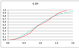 | Figure 1. The theoretical CDF (blue line) compared with the measured CDF (red line) |
Figure 1 presents one of the results of statistical processing for a particular measurement. Experimental graph (red line) is compared with the theoretical one (blue line). On the vertical axis given the probability that the measured field values are smaller or equal to the value correspondent to the horizontal axis. The more experimental graph approaches theoretical graph, stronger is depolarization of field, so the recipient can receive useful signal in any position. Deviation from the theoretical result means that the field contains a dominant component to the others.
3. The Measurement of S Parameters of Wi-Fi Antennas
3.1. S Parameters Definition
S parameters are considered those of scattering matrix. S parameters can be measured instantly and easily with a network analyzer.If we have a network with N gates, where VN+ is the amplitude of the incident voltage wave on the gate n, and VN- represents the amplitude of the reflected wave from the gate n, then the matrix equation is taken. | (3.1) |
The elements of matrix S are defined: | (3.2) |
Where Sij is determined by the incident wave with the amplitude Vj+ towards gate j, and by measuring the amplitude of reflected wave Vi- arising from the gate i, by reversing the incident voltage on all other ports than port j.In our measurement model we assumed a network with two gates that are represented respectively by antennas Wi-Fi and UMTS, and have derived the equation (3.3): | (3.3) |
V1+ is the incident voltage wave on gate 1. V1- represents the size of the reflected wave of gate 1. Based on equation (3.2) S11 and S21 parameters are determined: | (3.4) |
 | (3.5) |
Consequently S11 parameter is the reflection coefficient, or the ratio between the reflected and incident signal in antenna, while the S21 is a transmission parameter, so a measurement that shows how the signal radiated from an antenna is influenced and absorbed by the other.The result is that the smaller the reflection coefficient, the smaller will be the consumed reflective power. Similarly, it is required to minimize the value of parameters S12 and S21, because as small as transmission coefficients are from one antenna to another, the smaller the interference between two antennas will be.
3.2. Determination of Measurement Conditions
Network analyzer[12] is undoubtedly the most appropriate instrument to perform measurements of S parameters. It is a tool used to analyze the characteristics of electric networks, particularly the behavior concerning the reflection and transmission of electrical signals. For measurement of S parameters in the module and phase is used the vector network analyzer Agilent 8753D, calibrated to eliminate internal faults of the instrument itself.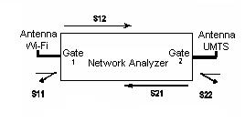 | Figure 2. Bank configuration for the measurement of S parameters |
The band selected for measurements extends from 1.8 GHz to 2.5 GHz, in order to recover both the UMTS and Wi-Fi, without the need of different calibrations, for measurements in two different bands. Power supply is 0dBm, enough to operate the instruments and operators in safely way and to get the needed results. Bank of measurements (Fig. 2) consists of a network analyzer with two gates associated respectively with two antennas.We specify, in fact, that the parameters taken in consideration are only parameters S21, not S12 that mean that will be studied only UMTS antenna interference on the Wi-Fi. This is because UMTS uses an already analyzed and studied technology for realizing multiple physical accesses, and Wi-Fi today still presents significant problems in terms of security.Measurements were repeated by changing the polarization of each antenna as well as the configuration of the surrounding environment, so that can be observed possible changes of the electromagnetic antennas behavior, by various simulated realistic environments. The studied antennas are 3 Wi-Fi antennas: Wi-Fi 1 (Dipole), Wi-Fi 2 (Yagi), Wi-Fi 3 (Patch) and 3 antenna UMTS: UMTS 1 (Katrein 738454), UMTS 2 (Katrein 741573) and UMTS 3 (Electromagnetic Services XD 1412V) which have common characteristics and distinctive features between them [13][14].
3.3. Simulation of the Environment around the Access Point
The environment configurations, where S parameters measurements were performed are 4 types (Fig. 3):• Environment in free space realized with pole sterol;• Environment with metal structure realized with three metal plans for expanding the reflective surface;• Environment with bricks for simulating the possible installation of such antennas on a wall surface;• Environment with entirely metallic plan.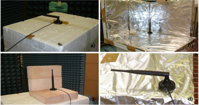 | Figure 3. The environment simulation: a) in free space, b) in metallic structure c) with bricks, d) over metallic plan |
3.4. Types of Measurements
To better characterize the reflection coefficient or parameter S11 for each Wi-Fi antenna on their own, we have committed these types of measures: a) the S11 parameter depending on the environment, antenna polarization and antenna type b) S11 parameter without UMTS presence and in the presence of UMTS.The aim of these measures is how the S11 parameter is modified with the change of orientation of the antenna and the environment where it is positioned. The collected data will be compared to highlight the exact indication of the behavior of these antennas, in order to determine which antenna provides the best solution of all possible cases.The next group of measurements was conducted to study the behavior of UMTS antennas and Wi-Fi when these antennas are staying in the same access environment[15]. The aim is to consider how these two types of antennas effect to each - other. Parameter S21 is precisely the one that reflects this impact. So for the couple Wi-Fi - UMTS, measurements were performed for the S21 dependence on the type of environment, type of polarization, the antennas couple and distances between them.We will compare the occurrences of different couple of antennas for each possible configuration, defining which solution offers the best performance for each specific case.
4. Results of Measurements
There are many measurements performed in this study but we will present only some of them through graphics. In each graphic is highlighted the dependence of the relevant S parameter by the change of one of the parameters, holding fixed all other parameters.
4.1. S11 Dependences on the Type of Environment
In this experiment we analyze how S11 parameter is changing for the Wi-Fi 1 antenna when we change the environment, in a certain position. In Fig. 4 are given the results of measurements on three environments with Wi-Fi antenna in a vertical position.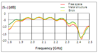 | Figure 4. Measurements of S11 in three environments |
 | Figure 5. Measurements of S11 in three types of polarization for Wi-Fi 1 |
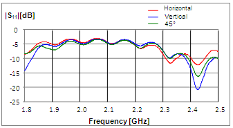
4.2. The Dependence of S11 on the Type of Polarization
In Fig. 5 we use the metal plan environment and one type of antenna and have performed measurements by changing the polarization of this antenna.
4.3. S11 in the Presence of the Second Antenna
If we referrer to the conditions, those of an access space where two antennas are installed, one for Wi-Fi services and the other for UMTS services, will see how the S11 parameter, is affected from the presence of a second antenna, because this second antenna is a radiating structure that modifies the structure of the measurement conditions.In Fig. 6 we compare S11 parameter in the absence of UMTS, and in the presence of the UMTS for three different distances of antennas couple.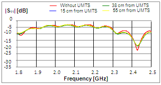 | Figure 6. Wi-Fi 1 antenna horizontally polarized in free space |
4.4. The Dependence of S21 on Antenna Polarization
At Fig. 7 is presented the S21 parameter depending on the polarization of Wi-Fi antenna, where the maximum value of S21 is in the vertical polarization. UMTS antenna is kept fixed in its vertical polarization. 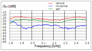 | Figure 7. Measurement of S21 in three types of polarization in free space |
 | Figure 8. Wi-Fi 1 antenna in different environments in a vertical polarization in presence of UMTS 1 |
4.5. The Dependence of S21 on the Type of Environment
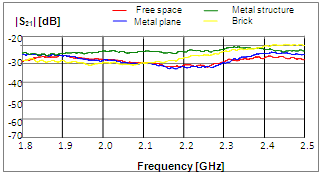
Let us analyze how the S21 parameter is affected when the environment varies. For this is fixed the distance 15cm between the two antennas. For a given polarization there are given the graphical results, in which it will be detected how S21 will change with the environment variation (Fig. 8).
5. Discussion
In the measurement S11 module, if we keep fixed the type of antenna and its polarization and change the environment, we note that the lowest value of coefficient of reflection, so the best adaptation is the wall environment, excluding the environment free space which represents the ideal case. While in the environment with metal structure, the value of S11 is greater, thus presenting the worst case.Changing the slope of antennas will bring changes, of the S11 value. Let us analyze in particular the environment with metallic plan (Fig. 5). We note that in Wi-Fi 1antenna, being omni directional, the value of parameter S11 is greater in the metallic plan and the value of this parameter is maximal in the horizontal polarization.While Wi-Fi 2 and Wi-Fi 3 antennas are directive, so in their case S11 is greater when it is placed in vertical position, because when placed horizontally, the metallic plan is intersected in a minimum point of their radiation diagram, so it has a small impact on the S11. In any case, for the three antennas, the largest differences are obtained for horizontal and vertical positions, as expected theoretically, whereas for 45° angle is taken intermediate values.If we refer to the measurement of transmission coefficient (Fig. 7) for the case when we keep fixed the couple of antennas type and the environment and change the antenna polarization of one another, it appears that the maximum value of S21 is in a vertical position, which decreases on 45° and has minimal value in the horizontal position of the Wi-Fi 1 for vertical UMTS 1.This was expected from theoretical reasoning through radiation diagrams that when two antennas have the same polarization they have maximal interference and when they are with orthogonal polarization have minimal interference.The large number of measurements and the presence of some variable parameters inspire discussion. But in this paper we present only some of them among the most typical.The data extracted from this paper will apply for setting up a new system that offers both services simultaneously in the same access space. Future work would be focused on statistical processing of the data so that may be issued a general pattern on the signal propagation in similar indoor environments.
6. Conclusions
From the analysis of coverage measurements in three considered environments, a good result came in the coverage area served by a single Wi-Fi antenna transmission. Therefore we can concentrate on the objective of our paper that is to determine which couple of antennas must be used in specific environments considering which among them are the most suitable antenna and less interfering.Conclusions will not be considering the environment free space, because it represents a situation that is not found in real domestic premises. It will be considered the case of antennas located at the orthogonal polarization and in a distance of 15 cm from each - other, distance which is used for the current access point.From the results of measurements are presented two proposals for the access point configuration which offers Wi-Fi and UMTS services.When the objective is filling the area as much as possible inside a building, the best antennas to use are those Omni Directional, therefore, in our case the antenna that will be used is Wi-Fi 1. Suggested couples are given in Table 1.Table 1. Most appropriate couples for situation 1
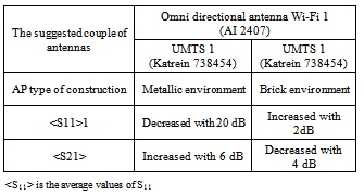 |
| |
|
When the objective is to cover only a particular area of the building, avoiding for example the signal radiation in the outdoors to avoid causing interference and to avoid connections from others from its local network, the best antennas to use are those directives, and in our case, results the most appropriate Wi-Fi 3 antenna, because it is assumed to be placed horizontally to have the orthogonal polarization with UMTS, this represent the best adaptation. Suggested couples for situation 2 are given in Table 2.Table 2. Most appropriate couples for situation 2
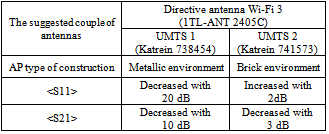 |
| |
|
ACKNOWLEDGEMENTS
We thank Professor Roberto De Leo who offered the possibility of using his department's laboratory at the University of Ancona, Italy, Professor Graziano Cerri for his technical assistance, the working group with which we realized the measurements, Fioranelli and Mariano Francesco Di Rienzo and professor Rozeta Miho, who enabled our presence for a period of 6 months at this University.
References
| [1] | Fioranelli Francesco, Cerri Graziano, “Caratterizzazione della copertura per sistemi wireless indoor in diverse tipologie di ambiente”, Eng. Thesis, Polytechnic University of Marche, Italy, 2007. |
| [2] | Thomas M. Schäfer, Jürgen Maurer and Werner Wiesbeck, “Measurement and Simulation of Radio Wave Propagation in Hospitals”, Vehicular Technology Conference, 2002 IEEE 56th, pp. 792-796, Vol.2. |
| [3] | S.Ramo, J.R. Whinnery, T. Van Duzer “Fields and waves in communication electronics, 3rd edition”, John Wiley & Sons, chapter 3 and 6, pp. 114-162 and 274-313, USA, 1994. |
| [4] | Nicola Albano “Modelli innovativi per la radiolocalizzazione, la progettazione e la pianificazione di reti cellulari outdoor e indoor”, Dissertation, Polytechnic University of Bari, Italy, 2007. |
| [5] | N. Albano, M. Canaletti, A. D’Orazio, M. De Sario, G. Gaudino, V. Petruzzelli, F. Prudenzano, “Measurements and Modeling of Propagation Losses in Buildings at 1.8 GHz and 2.1 GHz”, 2006 IEEE Antennas and Propagation Society International Symposium, Albuquerque, New Mexico, 4-9 July 2006, pp. 3089-3092. |
| [6] | Mehmet Yavuz, Farhad Meshkati, and Sanjiv Nanda, Qualcomm Inc, Akhilesh Pokhariyal and Nick Johnson, ip.access Ltd, Balaji Raghothaman and Andy Richardson, Airvana Inc, “Interference Management and Performance Analysis of UMTS/HSPA+ Femtocells” - IEEE Communications Magazine, September 2009. |
| [7] | M. Brandolini, P. Rossi and D. Manstretta and F. Svelto, “Toward multistandard mobile terminals - fully integrated receivers requirements and architectures,” IEEE Trans. on Microwave Theory and Techniques, vol. 53, Issue. 3, pp. 1026–1038, Mar. 2005 |
| [8] | Kotobelli Ezmerina, “Studimi dhe mbulimi me sinjal wireless Wi-Fi në mjediset e brendshme në prani të UMTS”. M. Eng. Thesis, Polytechnic University of Tirana, Albania, 2010. |
| [9] | Di Rienzo Mariano, Russo Paola, “Analisi della coesistenza di sistemi diversi su medesimo access point per servizi wireless in ambiente indoor”, Eng. Thesis, Polytechnic University of Marche, Italy, 2007. |
| [10] | Kotobelli Ezmerina, Renalda Kushe, “Analiza dhe përpunimi i matjeve mbi parametrat e antenave Wi-Fi në prani të UMTS në mjedise të ndryshme të brendshme”, “Roli i TIK në zhvillimin e shoqërisë shqiptare” – Conference, Tirana 2010, Albania. |
| [11] | Manual Handheld Spectrum Analyzer R&S FSH. |
| [12] | Manual Agilent E5070 – 90410 Network Analyzer. |
| [13] | Costantine A. Balanis, “Antenna theory: analysis and design, 2nd edition”, John Wiley & Sons, USA, chapter 1 and 2, pp. 1-114, 1997. |
| [14] | Testing Mobile Radio Antenna Systems with R&S FSH, pp. 1-36, 2004. |
| [15] | Kotobelli Ezmerina, Renalda Kushe, “Wi-Fi Behavior in Presence of UMTS for Indoor Environment” – NBIS 2011, Abania. |
 Abstract
 Reference
 Full-Text PDF
 Full-Text HTML