Hirokazu Kobayashi , Yoshio Yamaguchi , Yi Cui
Department of Information Engineering, Niigata University, Niigata, 211-8121, Japan
Correspondence to: Hirokazu Kobayashi , Department of Information Engineering, Niigata University, Niigata, 211-8121, Japan.
| Email: |  |
Copyright © 2012 Scientific & Academic Publishing. All Rights Reserved.
Abstract
This paper presents a simple and practical method and measurement results of transformation by using the idea of array-factor for direct far-field prediction from the near-field data of antenna and RCS in cylindrical scanning system. When radiation pattern of an antenna or scattering pattern of radar cross-section (RCS) is measured, its characteristics is usually evaluated in the far-field area. However, measurement is usually done in the radio anechoic chamber to reduce unnecessary reflected wave and deviates from the condition of far-field according to the size or the measuring frequency. On the other hand, it is well known that methods such as compact-range or the transformation processing approach can transform the pick-up data from the near-field to the far-field. The measurement results by this simple near-field transformation agree very well with the conventional far region measurement method.
Keywords:
Near-Field Transformation, Far-Field, Array-Factor, Cylindrical Scanning, RCS
1. Introduction
Electromagnetic wave propagation caused by a source can be also considered as the result of an equivalent secondary source between the wave source and observation point. When the electromagnetic field in an area near the source is known by some methods then the field in other areas can be theoretically predict. Thus a near-field measurement method can be applied to predict the antenna or radar cross-section (RCS) pattern which cannot be physically measured from far distance. The exact method of near-field to far-field transformation has been reported from 1970s for antenna[1-4] and RCS measurement[5],[6]. It is a traditional and well-established approach to formulate the electromagnetic field relation between the probe and the antenna under measurement using modal expansion method according to the ways of probe scanning which can be classified into three major types: flat-plane, cylindrical, and spherical scanning. The flat-plane scanning type is the simplest, and as a result, we can easily obtain the far-field from the data of near-field distribution using fast Fourier transformation (FFT). It is, however, difficult to apply the FFT for the other scanning types, i.e., cylindrical or spherical, and selection of the scanning type depends on the directivity of the antenna or the beam width of the RCS. In this paper, we present a method that available to apply in any scanning type.When array antenna is studied, it is common to use array-factor (AF) for representing the electromagnetic far-field which is the result of the radiation of array elements as small point sources. The AF is a basic theory for beam-forming of phased array antenna, adaptive array processing and so on. This AF concept can be also directly applied to the near-field to far-field transformation. The formulation of the AF is very simple as compared to the complicated modal expansion method which needs various special functions according to the scanning plane. In addition, AF based method is only dependent on the coordinates of the probing sample points, which is one of its major features. In this paper, we mainly discuss the far-field transformation in circular cylindrical scanning for antenna and quasi -bistatic RCS patterns.
2. Array-factor of a Ring and Cylindrical Array
When the same isolated elements are arranged in the linear and homogeneous space, assuming there is no mutual coupling among elements, the AF in terms of angular variables of the spherical coordinate system  is:
is: | (1) |
where  are the 3-dimensinal coordinates of the
  element,
 is the wave-number and
  is the wave-length. Eq. (1) expresses the far-field pattern which is produced by point sources. If we use the measured electromagnetic field distributed near the antenna instead of the AF element as point source then it is expected that Eq. (1) shows the far-field radiation pattern of the antenna. Furthermore, this expression is already in a fashion of the far-field pattern, and the near-field data can be directly transformed to the far-field by putting the phase and amplitude of these near-field data to the complex number coefficient,
  The flat-plane scanning is suitable for measurement of high directivity antenna such as the aperture antennas[3]. On the other hand, the cylindrical (circle) scanning based on ring array is known to be best for patch and/or wire antenna and so on with broad pattern. The processing of FFT is employable in the flat-plane scanning system, but, unfortunately, not in other scanning system like cylindrical or spherical. In this study we mainly concentrate on the cylindrical scanning system but as will be seen later, the proposed transformation method using AF in Eq. (1) is independent on scanning types. It only needs the near-field phase and amplitude data,
  at coordinates
 .
.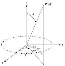 | Figure 1. Geometry of a ring array and spherical coordinates |
In order to discuss the ring array theory, we analytically expand Eq. (1) as follows. When N same elements are arranged on a circumference in the x-y plane as shown in Fig. 1, the AF of a ring array, by setting  in Eq. (1), becomes
 | (2) |
where  is angle of the element antenna and
  is the radius of the circumference. We can easily obtain the far-field transformation by putting the measured data in the complex coefficients
  Introducing new variables
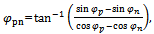
 | (3a) |
 | (3b) |
Where  are angles for the maximum beam, then Eq. (2) can be simplified as
 | (4) |
This expression saves the computing time, even though the element number, N, is comparatively large. Another form of the ring array using the Bessel function is also available by:  | (5) |
where  is the Bessel function of the first kind with order pN. If the maximum beam direction is
  and N is comparatively large (e.g.,
  Eq. (5) approximately becomes
 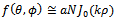 in both horizontal and vertical planes.Next, the directivity of a ring array is considered. The directivity is defined by the radiation field
  divided by the average receiving power density
  of the array. The factor of
  of the average power density originates in an isotropic reference antenna. The directivity in the direction of the maximum beam is especially called gain of directivity, which is expressed as
 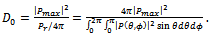 | (6) |
This  is usually evaluated by numerical integration. However, in the case of a ring array we show the above denominator
  can be analytically calculated as follows.First, for any
  a relation
 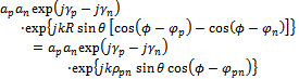 | (7a) |
 | (7b) |
 | (7c) |
 | (7d) |
can be derived. Substituting the above relation to the denominator of Eq. (6), we get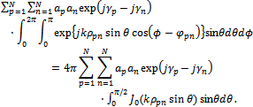 | (8) |
Finally, the result is expressed as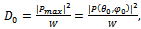 | (9a) |
 | (9b) |
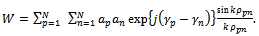
The above described AF and directivity are effective for element antenna with omni-directional pattern. If the pattern of element antenna have a form of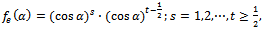 | (10) |
Where  is the angle measured from bore-sight of the element antenna, the factor W of Eq. (9b) then becomes the following closed-form:
 | (11) |
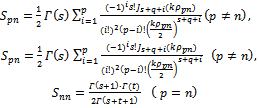 where
where  are the Gamma and Bessel functions, respectively. For example, for vertical short dipoles, element antenna becom
 by setting
 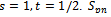 in Eq. (11) is given by
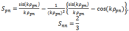 | (12) |
Eq. (2)-(5) are the AF expressions for a single ring array. When M-pieces of ring arrays of radius  overlap cylindrically, then by considering the z-axis, the single ring array Eq. (1) can be modified to
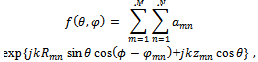 | (13) |
Where  are angles of the radiation pattern in the spherical coordinates. Each ring array is arranged in the same way. In other words, each element coordinates is same in the
  plane, i.e.,
  Moreover, the distance in the direction of the diameter is
  because the form of a cylinder is assumed.
3. Near-field Measurement for Antenna
In this section, we examine the procedure for predicting the far-field measurement. The phase and amplitude of the measured data in the near-field can be directly input to the complex coefficients  Since the radius of the cylinder is constant, one can set
  The probe antenna is linearly moved along the z-axis of the cylinder and the antenna under test (AUT) sitting on a pedestal is rotated around the z–axis as shown Fig. 2. At the same time, AF takes the probe pattern into account, and its compensation is as follows.
 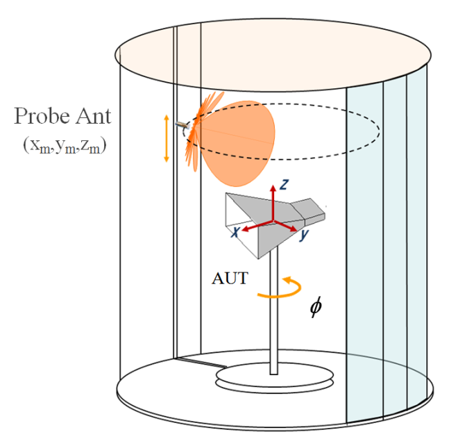 | Figure 2. Cylindrical scanning system of near-field measurement |
The pattern of the probe is assumed to be  where
where  and
and  are the local spherical coordinates at the sampling point of the measure data. The real pattern of the cylindrical array antenna system can be required by multiplying the AF to this element pattern as weighting. In order to evaluate the far-field without grating-lobe, it is necessary to know the beam pattern of the probe antenna,
  . Thus after the probe correction the far-field pattern Eq. (13) is simply modified to
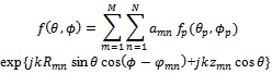 | (14) |
for 3-dimensional cylindrical scanning transformation. This compensation of the probe antenna to AF as element pattern weighting is the key point in array antenna theory for near-field to far-field transformation on non-flat scanning measurement. For simplicity, assuming the pattern of the probe antenna is  in a single layer of ring array, we can approximately convert the pattern to the scanning coordinates as
  . Then the far-field pattern Eq. (14) reduces to
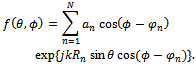 | (15) |
If the edge of the waveguide is selected as probe antenna then we may use the calculated tablet value of the horn antenna to correct the probe pattern. However, it can be expected that there is not so difference in the result of the far-field transformation even if it is replaced by the cosine function as mentioned above, from the viewpoint of the computing time. The directivity gain of the AUT is evaluated by using Eq. (9a) and the absolute gain including antenna loss can be evaluated using the substitution method for standard horn gains. In the actual measurement, sampling interval of the probe  and
and  become important parameters. The angle
  is rotated within the range of
  and
and  is limited to the area where the power level between the probe antenna and AUT is detectable. The movement interval of the probe can be chosen according to the sampling theorem. Usually the probe is measured outside the effective near-field which is several numbers of wave-length away. The interval of the sampling position at this time becomes a pitch satisfying
 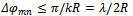 and
and 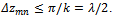
4. Far-field Transformation Results for Antenna and RCS
Fig. 3 is a photograph of the measuring system with the AUT and probe antennas as shown Fig. 2. For this cylindrical scanning measuremen
 ; the sampling interval are
  mm and
  at frequency 22 GHz. A measured example of amplitude and phase of the near-field using the cylindrical scanning system is shown in Fig. 4. The AUT is a standard pyramidal horn whose aperture is
  mm and the probe antenna is a single side of the standard waveguide (WR42) which is separated 270 mm away from the aperture of the AUT.According to Eq. (13), the 3- and 2-dimensional displays of the far-field transformation result using the measured near-field data in Fig. 4 is shown in Fig. 5 and Fig. 6, respectively. The result of conventional far-field measurement is also drawn in Fig. 6. It can be seen that both results agree very well.
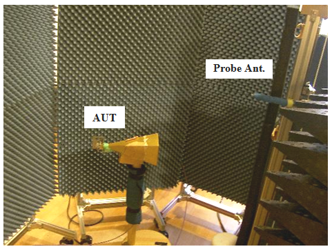 | Figure 3. Near-field measurement of cylindrical scanning |
 | Figure 4. Near-field measurement of a horn antenna in Fig. 3 at GHz, (a): amplitude, (b): phase distribution |
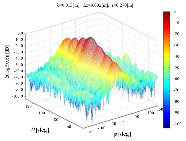 | Figure 5. Far-field 3-dimensinal pattern transformed from the near-field distribution in Fig. 4 by using AF |
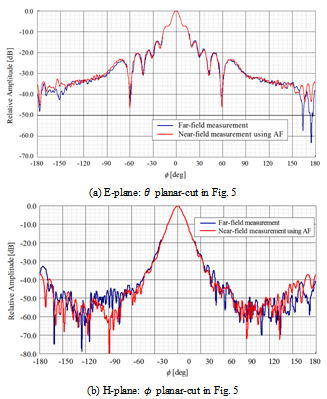 | Figure 6. Far-field 2-dimensional planar-cut patterns of Fig. 5 |
If the probe pattern is not taken into account, unnecessary grating lobe will appear in the rear direction of the AUT. Fig. 7 shows an example in which no compensation of probe antenna pattern is made to AF. It can be seen that the probe compensation is necessary for the measurement using AF. Since the flat-plane scanning is unable to simultaneously measure the antenna with the front and back lobes, the cylindrical scanning becomes the best method for antennas with or without pencil beam. On the other hand, the scanning in the direction of the z-axis is essentially the same to the plane scanning system. So, the aspect angle between the probe and AUT affects the measurement precision for this direction of cylinder scanning system.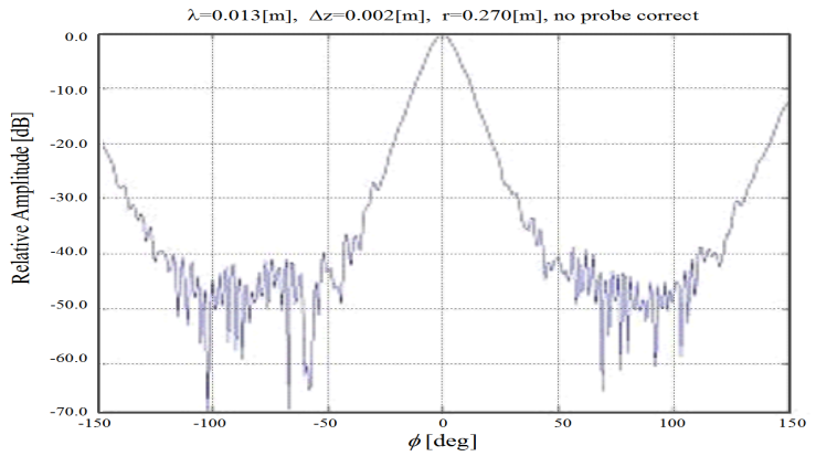 | Figure 7. An example without compensation of probe antenna pattern: measurement conditions are same in Fig. 6(b) |
As for the directivity evaluation, the difference between the result using the AF according to Eq. (9a) and the result based on the shape size is less than 0.3 dB. Using Eq. (6) directly, it is found that the results are almost the same.Next, we discuss the RCS measurement, which is a key parameter for radar system design. The RCS is defined by the formula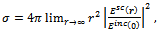 | (16) |
where  is a component of the scattered electric field at the observation point
  is a component of the incident electric field at the origin where the target is located; and
  is the distance from the origin to the observation point. Eq. (16) can be used only in the far-field region of the scatterer where the scattered field has the form of an outgoing spherical wave. The distance to the far-field region can be expressed in terms of the maximum linear size L of the scatterer and the wavelength as
  . This relation implies that in the microwave frequency range (frequency f between 1GHz and 100GHz) and for targets of several meters in size or larger, the far-field zone is located too far to permit a direct measurement of RCS. For example,
  m when
  m and
m and  GHz. This formula is also valid for far-field of antenna. Now we will show an example of RCS transformation by near-field measuring. However, the method for the antenna measurement introduced so far cannot be applied to the RCS measurement as it is because it is necessary to provide both transmitter and receiver for the RCS measurement system. Therefore, the transformation theory of the antenna can be applied to the RCS measurement by illuminating the whole area of the target by plane wave. When the size of the target is comparatively small, an incident plane wave can be made compulsorily by a compact-range system in the near zone of the target. Then the AF transformation algorithm is applied to the picked-up near-field data scattered from the target. Transmission and reception by the compact-range is only available for the monostatic mode, but not for the bistatic mode.Fig. 8 is a photo of the cylindrical RCS measurement using compact-range. Target whose size is less than
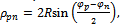
  mm may be illuminated by the plane wave of which the phase deviation is within
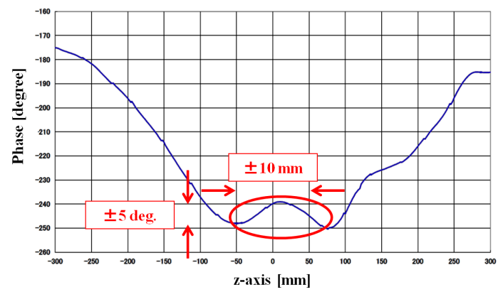
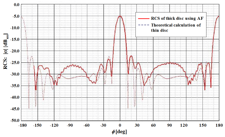
  deg. In this situation, the RCS transformation result is shown in Fig. 10. The target is a perpendicularly set-up circular metallic disc with diameter 81mm and thickness 5 mm. The distance between the receiving probe and the center of the disc is 190 mm and the measuring frequency is 10GHz. The compact-range transmitter is a parabolic reflector of diameter 1.2m which is 1.5 m from the center of the disc. Fig. 9 is the phase deviation plot around the quiet-zone, in which target under test will be located. The plane wave from the compact-range illuminates the disc at the incident angle of 15deg. As shown in Fig. 10, the direction 0deg corresponds to the specular reflection, -45deg., and it is in good agreement with the theory value in this direction of the main lobe. The error at the direction (
 deg.) for the theory calculation value is due to neglect of the thickness of the disc. The theoretical value for the thin disc is calculated by using the method of PTD (Physical Theory of Diffraction)[7].
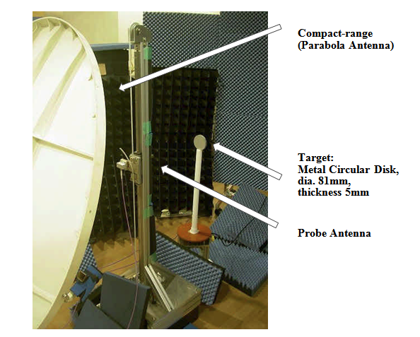 | Figure 8. RCS near-field measurement using compact-range in cylindrical scanning system |
 | Figure 9. Phase distribution around target quiet-zone in cylindrical measurement system using compact-range in Fig. 8 |
 | Figure 10. Near-field to far-field RCS pattern of a metallic circular disc illuminated by plane wave using compact-range |
5. Conclusions
In this paper, the near-field transformation method using the AF has been proposed and it was shown that applying the idea of the AF is an easy and simple concept to obtain enough accuracy. In addition, by producing the plane wave using compact-range, this antenna measurement method is easily extended to the RCS measurement as well. The near-field method can be applied even in the quiet-zone of poor performance as compared with the traditional far-field measurement. Furthermore, data are measured in the closed space by cylindrical scanning and it is proven that the measurement accuracy is good in the direction of circumference. On the other hand, the accuracy of the flat-plane scanning depends on the aspect angle to the AUT for the z-direction of the cylindrical scanning measurement. Applying FFT for transformation calculation in this flat-plane direction can shorten the computing time by approximately 1/10 times but it is not applicable to cylindrical scanning direction. Since the traditional modal expansion based near-field transformation for cylindrical scanning generally becomes too complex due to the use of special functions, it is advantageous to use this simple and effective AF-based approach as an alternative transformation method.
ACKNOWLEDGEMENTS
This work was supported in its measurement by Keycom Corp., Tokyo, Japan. The authors would like to thank the president, Mr. Hirosuke Suzuki.
References
| [1] | Appel-Hansen, J., Dyson J. D., Gillespie E. S., and Hickman T. G., "Antenna measurements," in the Handbook of Antenna Design, ed. A. W. Rudge, etc., pp. 584-694, IEE UK, 1986. |
| [2] | Yaghjian, A. D., An Overview of Near-field Antenna Measurements, IEEE Trans. on Antennas and Propagation, Vol. AP-34, No. 1, pp. 30-45, 1986. |
| [3] | Newell A. W., Planar Near-field Measurements, National Institute of Standards and Technology, Lecture Notes, 1989. |
| [4] | Slater, D., "Near-field Antenna Measurements," Artech House, 1991. |
| [5] | Hansen, T. B., Marr, R. A., Lammers, U. H. W., Tanigawa, and T. J., McGahan, R. V., Bistatic RCS Calculations From Cylindrical Near-Field Measurements—Part I: Theory, IEEE Trans. on Antennas and Propagation, Vol. AP-54, No. 12, pp. 3846 – 3856, 2006. |
| [6] | Kobayashi, H., Osipov, A., and Suzuki, H., An Improved Image-based Near-field-to-far-field Transformation for Cylindrical Scanning Surfaces, Proc. 30th General Assembly and Scientific Symposium of International Union of Radio Science (URSI), Istanbul, Turkey, B04-3, August 2011. |
| [7] | Kobayashi, H., and Hongo, K., Scattering of Electromagnetic Plane Waves by Conducting Plates, Electromagnetics, vol.17, no.6, pp. 573-587, 1997. |
 Abstract
 Reference
 Full-Text PDF
 Full-Text HTML