-
Paper Information
- Next Paper
- Previous Paper
- Paper Submission
-
Journal Information
- About This Journal
- Editorial Board
- Current Issue
- Archive
- Author Guidelines
- Contact Us
Journal of Wireless Networking and Communications
2012; 2(4): 35-42
doi: 10.5923/j.jwnc.20120204.02
VHDL Design and FPGA Implementation of a Fully Parallel Architecture for Iterative Decoder of Majority Logic Codes for High Data Rate Applications
 Abstract
 Reference
 Full-Text PDF
 Full-Text HTML
M. El Haroussi , M. Belkasmi
SIME Laboratory, ENSIAS, Mohamed V Souissi Univ., Rabat, Morocco
Correspondence to: M. El Haroussi , SIME Laboratory, ENSIAS, Mohamed V Souissi Univ., Rabat, Morocco.
| Email: |  |
Copyright © 2012 Scientific & Academic Publishing. All Rights Reserved.
In this work, we propose a design and FPGA (Field Programmable Gate Arrays) implementation of three parallel architectures for majority logic decoder of low complexity for high data rate applications. These architectures are hard decision decoder architecture (Hard in - Hard out (HIHO)), the SIHO threshold decoding (Soft in – Hard out) and the SISO threshold decoding (Soft in – Soft out). The chosen code is the Difference Set Cyclic DSC code. The VHDL (Very high speed integrated circuit Hardware Description Language) design and the synthesis of such architectures show that such decoders can achieve high data rate with low complexity. In our case, the iterative decoder associated to the fully parallel SISO threshold decoders allows achieving high data rates, 2 clock cycles for two iterations with a complexity of 7350LEs.
Keywords: Error Correcting Codes, Iterative Decoding, Majority Logic Decoding, Threshold Decoding, VHDL Language, FPGA
Article Outline
1. Introduction
- The complexity and the latency, which are often higher during the decoding process, make up the major decoding drawbacks in the current digital systems. The decoding data rate depends of the parallelism of the chosen architecture, i.e., its ability to process simultaneously multiple data. The architecture presents a high level of parallelism more it is able to achieve a very high data rate. In electronic design, the complexity of the circuit (i.e., its surface) is often considered as a critical parameter. In this context of very high data rate, operating speed must be maximized with limitation of complexity induced by the parallelism of calculations. We will specially study the decoding of the codes belonging to the OSMLD (one step majority logic decoding) codes family [3-5] and used in an iterative decoding process. The majority logic decoding uses a linear combination of a reduced set of syndromes represented by orthogonal equations. Hence it allows, by choosing a pipeline and / or parallelized architecture, to have a less complex decoding circuit with a high data rate. The principle of majority logic decoding and the proposed VHDL design and FPGA implementation of majority decoder with a hard decision is described in Section 1, the Section 2 present the VHDL design and FPGA implementation of architecture of the Massey's APP (A Posteriori Probability) algorithm[3]. The Section 3 present the VHDL design and FPGA implementation of a fully parallel architecture of SISO threshold decoding, using the joint exploitation the parallelism of symbol and the parallelism of sub-blocks so as to achieve high data rate. In Section 4, we will describe the iterative algorithm used to decode the OSMLD codes. Before concluding we will present the results of our simulations.
2. Decoding Majority Logic Codes
- A. Simple majority logic code (MLC)Consider a linear cyclic code C (n, k) with H parity-check matrix. The space generated by H is the cyclic code (n, n-k), denoted by C┴, which is the dual code of C, or the null space of C. For any vector v in C and any vector w in C┴, the inner product of v and w is zero. Now suppose that a code vector in C is transmitted over a binary symmetric channel. Let e (e1, e2, .…, en) and R (r1, r2, …, rn) be the error vector and the received binary vector respectively. Then R = v + e. For any vector w in the dual code C┴, we can form the following linear sum of the received digits:
 This is called a parity-check sum. Using the fact that
  | (1) |
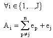 Example:Let C (7, 3, 4) be the cyclic majority logic and DSC code having three orthogonal equations.A1 = e4 + e5 + e7A2 = e2 + e6 + e7A3 = e1 + e3 + e7B. hard-input hard-output Majority logic decoding (MLD)The parity check equations orthogonal on en can be used to estimate or to decode the received bit rn, The value can be determined by the following:● If at least J-(J / 2) +1 values of Aj are equal to 1 then the decision is en= 1,● Otherwise, the decision is en=0.C. Implementation of the parallel Majority logic decoderTo implement this decoder, we have transcribed the decoding steps on simple blocks described in VHDL and assembled as shown in Fig 1.
 | Figure 1. Parallel implementation of the proposed architecture for DSC code |
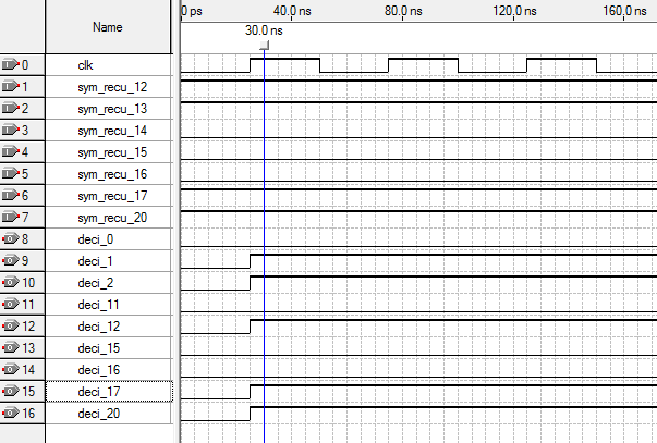 | Figure 2. Example of functional simulation of Majority Decoding |
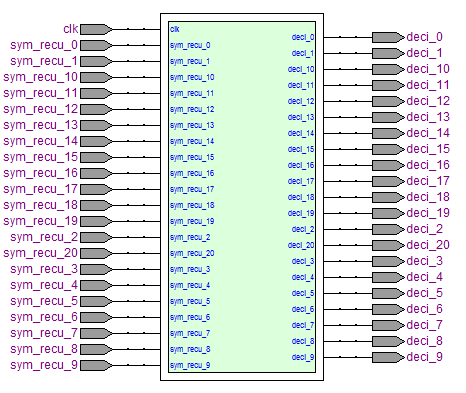 | Figure 3. VHDL model (fully parallel) of hard decoding of DSC (21,11) code |
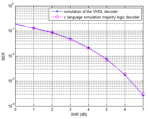 | Figure 4. Comparison of the performances of two decoders for the DSC (21, 11) |
3. Design of the Threshold Decoding
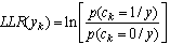
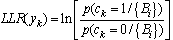
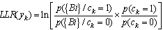
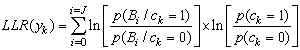
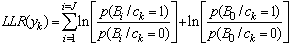
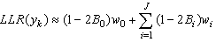
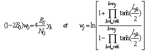
- A. threshold decodingIn this section, we present the algorithm of threshold decoding [3]. We keep the same notations as those adopted in the previous section, assume the existence of J equations orthogonal on each position.We consider a transmission of a codeword c (c1, c2, ... cn), using BPSK modulation over a channel with additive white Gaussian noise (AWGN). Suppose that the word y (y1, y2, ..., yn) is the received word. The decoder calculates for each bit yk the Log Likelihood Ratio LLR defined as follows:
 | (2) |
 | (3) |
 | (4) |
 | (5) |
 | (6) |
 | (7) |
 | (8) |
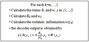
 .The term
 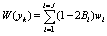 is extrinsic information representing the estimation of the orthogonal equations on the symbol yk. Thus (8) becomes:
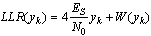 | (9) |
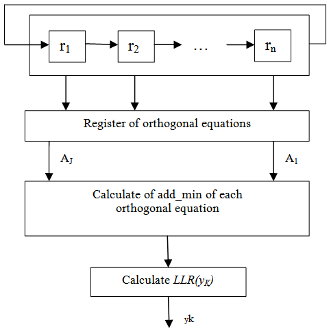
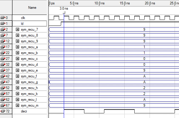
 B. Architecture of the threshold decoderThe entry consists of analogy samples (called symbols) encoded on q=4 or 5 bits: 3 or 4 bits for reliability and 1 for sign. The sign bit represents the binary value of the symbol ('0 'or '1'), the absolute value of a received bit represent its reliability (high reliability means that this bit has more chance to be correct).We can simplify the implementation of the log likelihood ratio using an operator ADD_MIN [6] noted ◊. This operator searches the minimal value in absolute among n inputs and computes the sign according to the product of inputs signs.The simplified expression of the decoder output becomes:The figure 5 presents the description, after simplification, the steps decoding from simples blocks described in VHDL and assembled. The architecture of the threshold decoding has three fundamental units which are:● The shift register contains the quantified symbols received in parallel, the loading of the register is controlled by Ld input on the first rising front of the clock (see figure 6) and with each new rising front of the clock the shifted symbols are available at the register output. ● In the implementation of the add-min operator and the adder, the number of input ports must be configurable as well as the number of bits per port to avoid poor performance of the correction errors caused by deficient resolution of different operators within the architecture. ● The results of the add-min operation, the addition and the decision are available at the output at each rising edge of the clock.
|
 | Figure 5. Parallel implantation of proposed architecture of the threshold decoding of MLC code |
 | Figure 6. The VHDL model of threshold decoding of DSC (21, 11) code. |
 | Figure 7. Example of functional simulation of our decoder |
 | Figure 8. Comparison of performance of the Threshold decoder of DSC (21, 11) code in C language simulation and hardware level simulation |
4. Design of Parallel Architecture of the SISO Threshold Decoding
- A. Designe of SISO threshold decodingThe basic idea is to modify the conventional threshold algorithm by associating a reliability to each decision to be exploited in iterative decoding [1][2][11-13].
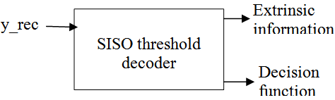 | Figure 9. Implementation of soft-output decoder |
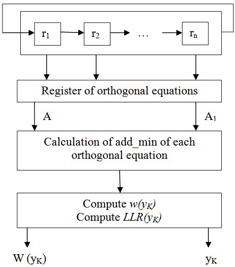 | Figure 10. Parallel Implementation of proposed architecture of the SISO threshold decoder of an OSMLD code |
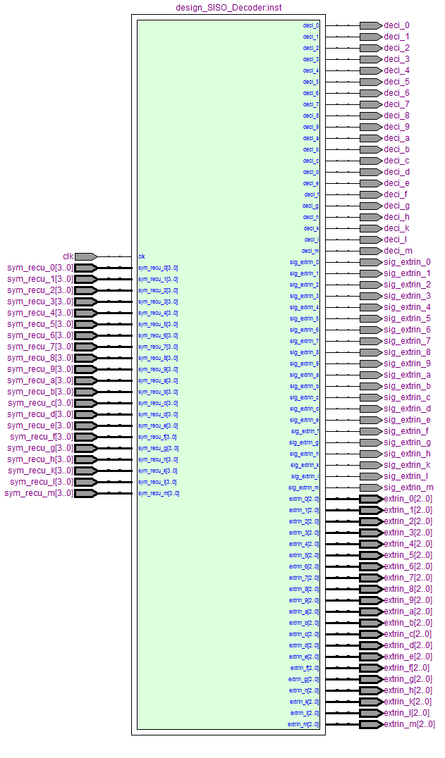 | Figure 11. The VHDL model of the fully parallel SISO threshold decoder of DSC (21, 11) code |
 | Figure 12. Example of functional simulation of our decoder |
5. Iterative Threshold Decoding
- A. Iterative threshold decodingThe iterative decoding of codes OSMLD was introduced for the first time by Lucas[14]. Two years after, the latter with Fossorier et al.[15] have proposed the belief propagation algorithm for decoding of OSMLD codes, in[16]. They showed that the iterative Hartmann-Rudolf-Lucas decoding, originally used for the decoding of product codes can be used to decode the codes OSMLD. In the process of iterative decoding, each decoder takes advantage of the extrinsic information produced by the other decoder in the previous step. How extrinsic information is transmitted and the way it is exploited by decoders to make their decision are not yet closed. The iterative decoding process that we use follows the Pyndiah’s scheme [9][10] (figure 13).
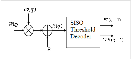 | Figure 13. Component decoder |
 Where R represents the quantified received word and
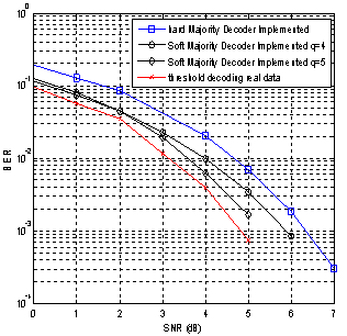
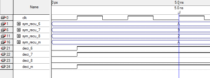
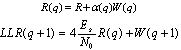
  the extrinsic information calculated by the previous decoder.B. Implementation of parralel iterative threshold decodingThe final design of the parallel iterative decoder is described in VHDL and embedded on FPGA using the Altera’s Quartus II tool. For the complexity of the global entity, the area occupied by the fully parallel iterative show in table 2 for the two codes DSC (21, 11) and DSC (73, 45) with 4 and 5 bits quantification. The figure 14 gives an example of functional simulation on which it is reported that the information presented at the input of the circuit decoder will be decoded on two rising edges of the clock for a two iterations, and for a number of iterations n_ite, latency is of n_ite clock cycles. We were able to simulate and verify the decoding of 2000 words used for each SNR following a simulation protocol. Figure 15 (resp. Fig.16) shows the performances of our iterative decoder using the quantified data of 5 bits and α(q) fixed for the DSC(21, 11) (resp. DSC(73, 45)) code.
 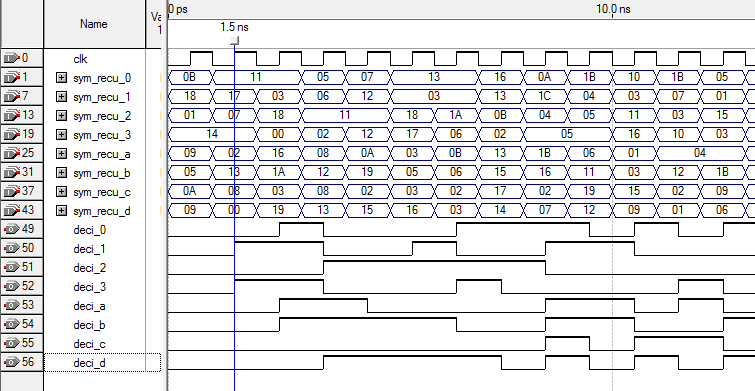 | Figure 14. Functional simulation of our decoder for two iterations |
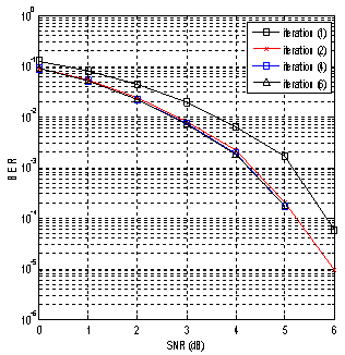 | Figure 15. Performance of our implemented fully parallel simple iterative decoder (DSC (21, 11) data quantified in q=5 bits alpha=0.5) |
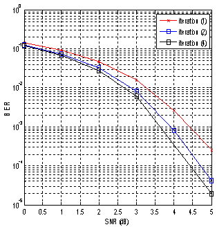 | Figure 16. Performance of our implemented fully parallel simple iterative decoder (DSC (73, 45) data quantified in q=5 bits alpha=0.2) |
6. Conclusions
- The VHDL design and FPGA implementation of an iterative decoder for OSMLD codes have been proposed in this paper. This design allows reaching and achieving very high data rate while minimizing complexity. By adopting a combinatory architecture operating in pipelined and/or parallelized mode, the SISO threshold decoder reacts on the first active front of the clock with a complexity of 3672 LEs for DSC(21, 11) code and q=4bits. Furthermore the iterative decoder associated to the fully parallel SISO threshold decoders allows achieving high data rates, (2 clock cycles) for a two iterations with a complexity of 7350LEs for DSC(21, 11) code and q=4bits. As a perspective we plan to study the DSC turbo decoder.
References
| [1] | C.Leroux, C.Jego, P.Adde et M.Jezequel,"Turbo décodage de codes produits très haut débit sur FPGA". Colloque GRETSI, 11-14 septembre 2007, TROYES, France. |
| [2] | E. Piriou "Apport de la conception d'architecture flexible dédiée aux turbo codes en blocs", PhD thesis, ENST Bretagne, Jan 2007 (in Frensh). |
| [3] | I. L Massey, “Threshold Decoding,” Cambridge, Mass. M.I.T. Press, 1963. |
| [4] | M. Lahmer, "Décodage à seuil itératif des codes à logique majoritaire". PhD thesis, ENSIAS, Rabat, 2008, Morocco (in French). |
| [5] | M. Belkasmi, M. Lahmer, F. Ayoub “Iterative Threshold Decoding of Product Codes Constructed From Majority Logic Decodable Codes ”, 2nd International Conf. on Information and Communication Technologies : From Theory to Applications, IEEE ICTTA’06, Apr. 2006, Damascus, Syria, pp. 2376 – 2381. |
| [6] | J. Hagenauer, E. Offer, and L. Papke, "iterative decoding of binary block and convolutional codes", IEEE Trans. Inform. Theory, Mar. 1996, Vol. 42, pp. 429-446. |
| [7] | M. Elamine,"Conception d'architecture rapides pour codes convolutifs en télécommunications: Application aux turbo-codes". PhD thesis, Metz university , France, 2003. |
| [8] | C. Clarck and B. Cain,"Error-Correction Coding for digital communications," Plenum Press, 1983. |
| [9] | R. Pyndiah, “Near optimum decoding of product codes: Block Turbo Codes", IEEE Trans. on Comm., vol 46, n°8, August 1998, pp. 1003-1010. |
| [10] | P. Adde, R. Pyndiah, J.R. Inisan et Y. Sichez. " Conception d’un turbo décodeur de code produit ". Colloque GRETSI’97, Grenoble, France, pp 1003-1010. |
| [11] | M.Elharoussi, A.Fouad, M. Belkasmi , “VHDL Design and FPGA Implementation of Weighted Majority Logic Decoders”, International Conference on Multimedia Computing and Systems (ICMCS’11) proceeding ,pp 397- 401, April 07-09,2011, Ouarzazate, Morocco. |
| [12] | M. Elharoussi, I. Chana, M. Belkasmi "VHDL design and FPGA implementation of a fully parallel BCH SISO decoder", 5th International Symposium on I/V Communications and Mobile Networks (ISIVC), Sept. 30, -Oct. 2, 2010, Rabat, Morocco. |
| [13] | M.Elharoussi, M.Belkasmi, "Implantation FPGA d’un turbo décodeur construit à partir des codes à logique majoritaire pour des applications Haut débit", International Workshop on Codes, Cryptography and Comminuction Systems (WCCC’11), June 16-17,2011, ENSIAS, Rabat, Morocco(in French). |
| [14] | R. Lucas, M. Bossert and M. Breitbach, "On Iterative Soft-Decision Decoding of Linear Binary Block Codes and Product Codes", IEEE Journal on selected areas in communications, February 1998, Vol. 16, N° 2, pp. 276-296. |
| [15] | R. Lucas, M. P. C. Fossorier, Yu Kou, and Shu Lin, "Iterative Decoding of One-Step Majority Logic Decodable Codes Based on Belief Propagation", IEEE Trans. Commun, Vol. 48, No. 6, pp.931-937, June 2000. |
| [16] | M. Belkasmi, M. Lahmer, “Iterative Threshold Decoding of One-Step Majority Logic Decodable block Codes”, ISSPIT Conf, December 15-18, 2007, pp. 668-673 Cairo, Egypt. |