-
Paper Information
- Next Paper
- Paper Submission
-
Journal Information
- About This Journal
- Editorial Board
- Current Issue
- Archive
- Author Guidelines
- Contact Us
Journal of Wireless Networking and Communications
2012; 2(4): 29-34
doi: 10.5923/j.jwnc.20120204.01
Reduced Complexity of Decoding Algorithm for Irregular LDPC Codes Using a Split Row Method
 Abstract
 Reference
 Full-Text PDF
 Full-Text HTML
Rachid El Alami , Mostafa Mrabti , Cheikh Bamba Gueye
LESSI Laboratory, Department of Physics, Faculty of Sciences Dhar El Mehraz, Fez, 35000, Morocco
Correspondence to: Rachid El Alami , LESSI Laboratory, Department of Physics, Faculty of Sciences Dhar El Mehraz, Fez, 35000, Morocco.
| Email: |  |
Copyright © 2012 Scientific & Academic Publishing. All Rights Reserved.
In this paper, we have proposed a novel method of decoding algorithm of irregular LDPC codes. A reduced complexity LDPC decoding method for regular LDPC code is extended to irregular LDPC codes. We present in this paper a full description of this method and its benefits for various row weight and length code word. The Split-Row method makes column processing parallelism easier to exploit and significantly simplifies row processors. Recently, irregular LDPC codes have received a lot of attention by many advanced standard, such as WiFi, WiMAX Mobile and digital video broadcasting (DVB-S2). Hence the idea to develop the “Split-Row Method” for irregular LDPC codes. In this context, we have performed an implementation on MATLAB of an irregular LDPC codes with different code word and code rate; simulation results over an additive white Gaussian channel show that the error performance of high row-weight codes with Split-Row decoding is within 0.3–0.5 dB of the Min-Sum algorithm. The study result shows that the “Split Row Method” is better for irregular code than regular LDPC codes.
Keywords: Low-Density-Parity-Check Codes, Split Row, Min Sum, Bit Error Rate
Article Outline
1. Introduction
- Low density parity check (LDPC) codes are a class of linear block codes which were first introduced by Gallager in 1963[1]. Recently, LDPC codes have received a lot of attention because their error performance is very close to the Shannon limit when decoded using iterative methods[2]. They have emerged as a viable option for forward error correction (FEC) systems and have been adopted by many advanced standards, such as 10 Gigabit Ethernet(10GBASET)[3][4] and digital video broadcasting (DVB-S2)[5][6]. Also the next generations of WiFi and WiMAX are considering LDPC codes as part of their error correction systems[7][8].In the present paper, the previously Split Row method for decoding regular Low-Density Parity-Check (LDPC) codes[9], is extended to irregular LDPC codes; a reduced complexity decoding method which splits each row module into two nearly-independent simplified portions. This method reduces the wire interconnect complexity between row and column processors and increases parallelism in the row processing stage. The Split-Row method also simplifies row processors which results in an overall smaller decoder; Defined as the null space of a very sparse M×N parity check matrix H, an LDPC code is typically represented by a bipartite graph, called Tanner graph, in which one set of N variable nodes corresponds to the set of code word, another set of M check nodes corresponds to the set of parity check constraints and each edge corresponds to a non-zero entry in the parity check matrix H. An LDPC code is known as (j,k) regular LDPC code if each column and each row in its parity check matrix have j and k non-zero entries, respectively. The construction of LDPC code is typically random. As illustrated in Figure 1, LDPC code is decoded by the iterative belief propagation(BP) algorithm[10] that directly matches its Tanner graph[11].
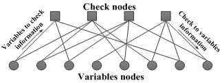 | Figure 1. Tanner graph representation of a LDPC code and the decoding message flow |
2. Standard Iterative Decoding of LDPC Codes
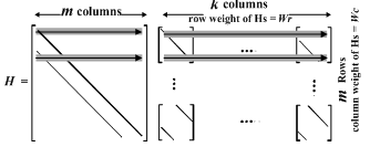
- LDPC codes are defined by an M× N binary matrix called the parity check matrix H. The number of columns represented by N defines the code length. The number of rows in H, represented by M, defines the number of parity check equations for the code. Column weight Wc is the number of ones per column and row weight Wr is the number of ones per row.LDPC codes can also be described by a bipartite graph or Tanner graph[11]. The parity check matrix and corresponding Tanner graph of an LDPC code with code length N=12 bits are shown in Figure 2. Each check node Ci corresponding to row i in H is connected to variable node Vj corresponding to column j in H. LDPC codes can be iteratively decoded in different ways depending on the complexity and error performance requirements.Sum-Product(SP)[10] is near-optimum decoding algorithms which are widely used in LDPC decoders and is known as standard decoders. This algorithm perform row and column operations iteratively using two types of messages: check node message α and variable node message β. The parity check matrix and the block diagram of the standard decoding algorithm are shown in Figure 3 and Figure 4 respectively.
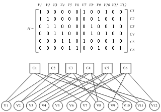 | Figure 2. Parity check matrix and Tanner graph representation of an irregular LDPC code with code length N = 12 bits. Check node Ci represents a parity check constraint in row i and variable node Vj represents bit j in the code |
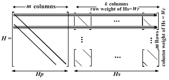 | Figure 3. Parity check matrix of an irregular LDPC code with code length N, highlighting row processing operations using standard decoding |
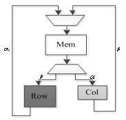 | Figure 4. Block diagram of a typical standard decoder |
2.1. Sum– Product Decoding
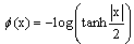
- We assume a binary code word (x1, x2, ..., xN) is transmitted using a binary phase-shift keying (BPSK) modulation. Then the sequence is transmitted over an additive white Gaussian noise (AWGN) channel and the received symbol is (y1, y2, ..., yN).We define V(i) = {j : Hij =1} as the set of variable nodes which participate in check equation i. C(j)={i : Hij =1} denotes the set of check nodes which participate in the variable node j update. Also V(i) \j denotes all variable nodes in V(i) except node j. C(j) \i denotes all check nodes in C(j) except node i. Moreover, we define the following variables which are used throughout this paper.λj: is defined as the information derived from the log-likelihood ratio of received symbol yi,
 | (1) |
 | (2) |
 | (3) |
 | (4) |
 | (5) |
 | (6) |
2.2. Min – Sum Decoding
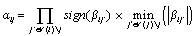
- The check node or row processing stage of Sum – Product decoding can be simplified by approximating the magnitude computation in Equation (2) with a minimum function. The algorithm using this approximation is called Min-Sum (MS)[14,15]:
 | (7) |
 | (8) |
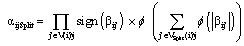
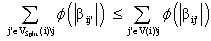
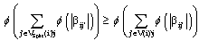
3. Split – Row Method Decoding Algorithm for Irregular Codes
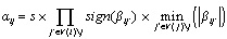
- The parity check matrix for the row processing stage of the proposed algorithm is shown in Figure 5. As shown in the figure, the row processing stage is divided into two independent halves. This architecture has three major benefits: 1) it doubles parallelism in the row processing stage; 2) it decreases the number of memory accesses per row processor; 3) it makes each row processor simpler. These three factors combine to make row processors (and therefore the entire LDPC decoder) smaller, faster, and more energy efficient. In addition, the Split-Row method makes parallelism in the column processing stage easier to exploit. To reduce performance loss due to errors from this simplification, the sign computed from each row processor is passed to its corresponding “half processor” with a single wire in each direction these are the only wires between the two halves. A block diagram of the Split-Row decoder with two memory blocks is shown in Figure 6.
 | Figure 5. Parity check matrix highlighting row processing operation with the Split-Row algorithm. For simplicity, a Quasi-Cyclic structure is shown for the systematic sub matrix Hs |
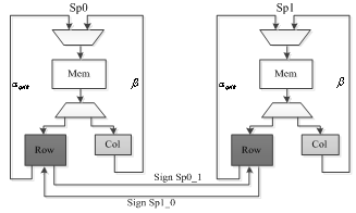 | Figure 6. Block diagram of the proposed Split-Row decoder |
 | (9) |
 | (10) |
 | (11) |
 | (12) |
 | (13) |
4. Error Performance Simulation Results
- To evaluate the extended method, Min Sum Split Row for irregular LDPC codes, we performed simulations assuming binary phase-shift keying (BPSK) modulation and transmission over the additive white Gaussian noise (AWGN) channel. These simulations have been carried out using MATLAB. For each simulation, a curve showing the bit-error rate (BER) versus Eb/N0 was computed. The Eb stands for energy per bit and the N0 stands for the noise power spectral density ratio.The following labeling is used for the figures: “MS” for normalized Min- Sum, “MS Split-Row” for the extended method Min-Sum Split-Row algorithm and “S” for the scaling factor.The performances of irregular LDPC codes are illustrated in the figures given below. Simulations were run to determine the performance of these LDPC in AWGN channel with BPSK modulation. In each case the proposed decoding algorithm was used. The decoder stops when a non-valid code word is found.Figure 7 shows the performance of the LDPC code with input frame size of 1536 bits and (6,18) as weights for the systematic sub matrix Hs. The code rate of this LDPC code is R=0.75. The max number of iterations is set to Imax =15. We fix the threshold Imax to satisfy a tradeoff between the performance correction and the speed of the decoder.In the Fig. 8, the bit error performance of LDPC code for an input frame size of 1520 bits and a (6,32) for the weights of Hs. The code rate is R=0.84 and the maximum number of iteration is set to Imax=15.Figure 9 depicts the bit error performance of LDPC code for an input frame size of 2014 bits and a (6,32) for the weights of Hs. The code rate is R=0.84 and the maximum number of iteration is set to Imax=7.From the conducted simulation study shown on Figure 7 and Figure 8 we can conclude that for a high row weight the performance gap between the standard Min Sum and the Min Sum Split Row is better than a low row weight; for example, in Figure 7, the gap is about 0.5dB while it is about 0.35dB in Figure 8.
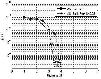 | Figure 7. Error performance of the Split-Row decoder for irregular LDPC code, N=1536 bits |
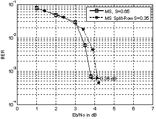 | Figure 8. Error performance of the Split-Row decoder for irregular LDPC code with code length N=1520 bits |
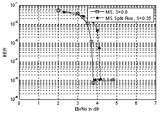 | Figure 9. Error performance of the Split-Row decoder for irregular LDPC code with code length N=2014 bits |
5. Conclusions
- In this contribution, we have extended the previous version the Split Row method developed for regular LDPC codes[9] to Irregular Codes. Simulation results show that the Split Row method is better for irregular code than regular LDPC codes while maintaining the same level of complexity.Future work will focus on implementation of the architecture of the present method of decoding algorithm for irregular LDPC codes. It consists also, to improve the proposed architecture of the decoder in order to achieve the best performance in terms of speed, throughput and flexibility.From the architecture of the present method mentioned in this paper; we have proposed a “Multi-Split-Row”[18] LDPC decoding method which allows further reductions in routing complexity, it also allows to have a faster decoder, compared to the actually proposed Split-Row decoding method presented in this paper.
ACKNOWLEDGEMENTS
- The authors thank Mostafa Mrabti have help us achieve this works and very helpful discussions; and gratefully acknowledge support from Maroc Telecom and CNRST.