C. Tienda1, J.A. Encinar1, E. Carrasco1, M. Arrebola2
1Department of Electromagnetism and Circuit Theory, Universidad Politécnica de Madrid, Madrid, 28040, Spain
2Department of Electrical Engineering, Universidad de Oviedo, Gijón, E-33203, Spain
Correspondence to: C. Tienda, Department of Electromagnetism and Circuit Theory, Universidad Politécnica de Madrid, Madrid, 28040, Spain.
| Email: |  |
Copyright © 2012 Scientific & Academic Publishing. All Rights Reserved.
Abstract
This paper describes an architecture for a Ku-band antenna based on a dual flat reflectarray configuration that provides electronic beam scanning within a 13 degree angular range. The antenna configuration presents the simplicity of being implemented with two flat reflectarrays, it provides a compact optics and it can be easily folded and deployed. The main reflectarray emulates a parabolic reflector and the beam scanning is achieved by introducing a phase-control into the elements of the sub-reflectarray. These elements are based on two stacked printed patches aperture-coupled to delay lines, which can be constructed using MEMS switches to provide electronic beam scanning.
Keywords:
Reflectarray, beam scanning, antenna
Cite this paper: C. Tienda, J.A. Encinar, E. Carrasco, M. Arrebola, Design of Dual-Reflectarray Antenna for Beam Scanning, Journal of Wireless Networking and Communications, Vol. 2 No. 1, 2012, pp. 9-14. doi: 10.5923/j.jwnc.20120201.03.
1. Introduction
A dual offset reflector antenna using a reflectarray sub-reflector and a parabolic main reflector has been proposed for beam steering within a limited range by implementing a progressive phase on the sub-reflectarray[1-2].The beam scanning can be used for several applications, such as Synthetic Aperture Radar (SAR) antennas and radiometric remote-sensing missions. The scan profile can be achieved using two different approaches: mechanical and electronic. The first approach is the solution used for classic parabolic reflectors[3] and is based on the mechanical rotation of the subreflector or the system constituted by the feed and the subreflector. The electronic scanning can be achieved by introducing a progressive phase shift on the sub reflectarray. The most relevant characteristic of this approach is the possibility of carrying out a dynamic scanning using reconfigurable elements such as pin diodes, MEMs or liquid crystals (LC)[4-7].This antenna configuration combines the high gain capabilities of the parabolic main reflector with the simplicity of manufacturing a small reconfigurable sub reflectarray[2]. In the dual-reflector configuration, the main reflector can be substituted by a flat passive reflectarray designed to focus the beam. The dual-reflectarray configuration shown in Fig. 1 exhibits some advantages when they are compared with conventional dual-reflector antennas. From a mechanical point of view, dual-reflectarray systems have lower volume and easy folding and deployment. From electrical features, they offer capabilities to scan or reconfigure the beam. Furthermore, the proposed dual reflectarray configurationprovides phase control on both reflectarray surfaces[8], which can be used to improve the antenna performance for multiple beams or beam scanning.A dual-reflectarray Ku-band antenna based on a 1-bit reconfigurable main reflectarray and a passive reflectarray sub reflector has been proposed recently to electronically steer a directive beam within a range of 13 degrees[9]. This antenna configuration suffers from the limitations derived of only 1-bit control, which produce high side lobes and a reduction in the antenna gain.In this work we propose an alternative dual-reflectarray antenna made of a passive main-reflectarray and a reconfigurable sub-reflectarray to provide beam scanning with improved performance in antenna gain and side-lobes with respect to other previously reported works[9]. The antenna is designed to provide a directive beam that can be electronically scanned within a range of 13 degrees. The original contribution of this work is to demonstrate through simulations that a beam can be scanned in a limited angular range by implementing phase-shifters in a reduced-size reflectarray subreflector. The reconfigurable elements are based on switched delay lines aperture coupled to square patches, that can be implemented by using either pin-diodes[10] or MEMS[11]. The analysis technique for the dual-reflectarray antenna has been proposed and validated previously[8], while the analysis of the reconfigurable reflectarray element has been validated for pin-diodes[10] and MEMS switches [11].
2. Antenna Definition
The antenna configuration has been selected to provide beam scanning on the elevation plane (XZ) within a range of 13 degrees using elliptical reflectarrays of axes (1175mm ×962mm) for the main and (250mm×225mm) for the sub- reflectarray. For a preliminary evaluation of the beam scanning performance, a phase is introduced into the sub- reflectarray to emulate the optics corresponding to different virtual foci, associated to each beam direction, as shown in Figure 1.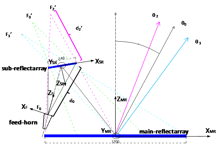 | Figure 1. Lateral view of the dual-reflectarray configuration |
The virtual foci determine a progressive phase along a dimension of the sub-reflectarray,  , p and q being the indexes of the sub-reflectarray cells that define the positions in the sub reflectarray, see (1)
 | (1) |
The main reflectarray is designed to emulate the behaviour of a parabolic reflector, producing a focused beam in (θ0,φ0) direction, in the YZ plane forming 0º with the Z axis, while the sub-reflectarray is used to introduce the appropriate progressive phase in order to scan the beam. The main data of the antenna optics is summarized in Table 1.
3. Antenna Design and Analysis
3.1. Antenna Design
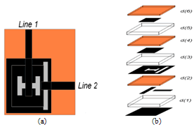 | Figure 2. Top view of the aperture coupled cell (a). Lateral view of the cell (b) |
The passive main reflectarray can be designed using stacked variable-sized patches[12] in a prescribed frequency band, the design can be performed like those reported in[8], however in this case, ideal phases will be considered for the main-reflectarray. The periodic cell has been chosen as 12.5mm×12.5mm for both reflectarrays. The reflectarray element for dual polarization proposed for the sub- reflectarray is shown in Figure 2, which is based on two stacked printed patches aperture-coupled to delay lines. This reflectarray element has been designed to provide the required phase variation in the frequency bands 10.7-12.75GHz and 14-14.5GHz,[13]. The phase control on the sub-reflectarray can be implemented by a 3-bit phase-shifter in the delay lines corresponding to each polarization. Figure 3 shows the phase-curves of the element for a 10.7GHz, 12.0GHz and 14.0GHz.| Table 1. Main data of the antenna geometry |
| | Main Reflectarray | | Main reflectarray size | 1175mm × 962mm94 × 76 elements | | Periodicity | 12.5mm × 12.5mm | | Subreflectarray(data in main-reflectarray coordinate system) | | Center | (-453, 0, 560)mm | | Direction cosines matrixof the sub referred to the main coordinate system |

| | Subreflectarray size | 250mm × 225mm20 ×18 elements | | Periodicity | 12.5mm × 12.5mm | | Feed-Horn(data in sub-reflectarray coordinate system) | | Phase centre | (356, 0, 616)mm | | Pointing (on the sub-reflector surface) | (15, 0, 0)mm |
|
|
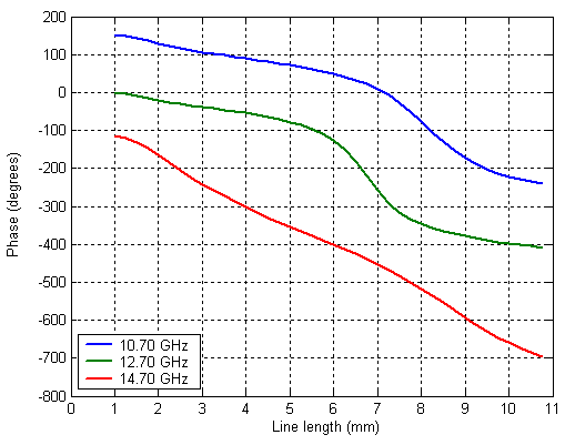 | Figure 3. Required phase shift of the aperture coupled element |
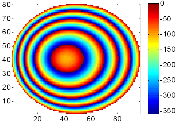
To evaluate the beam scanning performance, the phase distributions required on both the main and sub-reflectarrays have been computed for various scan angles. The phase distribution required on the sub-reflectarray to produce a beam scan of 5 degrees and -8 degrees in elevation (θ1 and θ2 in Figure 1) is shown in Figure 4(a) and Figure 4(b) respectively. The phase distribution required on the main reflectarray to emulate the behaviour of a parabolic reflector is shown in Figure 5 at 12 GHz. 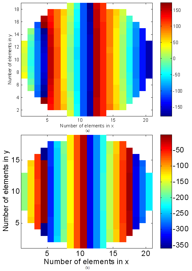 | Figure 4. Required phase for 5º beam deviation on sub-reflectarray (a) and required phase for -8º beam deviation on sub-reflectarray (b) |
 | Figure 5. Required phase distribution on main reflectarray |
3.2. Antenna Analysis Assuming Ideal Sub-Reflectarray
As a first step to analyse the antenna designed to steer the beam within a range of 13 degrees, ideal phases for both sub- and main-reflectarrays are considered. Figure 6 shows the module of the incident field on the main reflectarray when the sub reflectarray scans the beam from -8º to 5º. By varying the progressive phase distribution on the sub-reflectarray, the beam is steered from -8degree to 5degree with practically no distortion on the radiation patterns, as shown in Figure 7.Figure 8 and Figure 9 point out the 3D radiation patterns of the antenna for -8º and 5º scan respectively. Note that to achieve beam scanning by adjusting the phase-distribution only on the sub-reflectarray, the dimensions of the main passive reflectarray have been oversized, so that the beam radiated by the sub-reflectarray is impinging on only one part of the main reflectarray, depending on the scan angle, as shown in Figure 6. The beam scanning performance can be further improved by optimizing the phase distribution on the main passive reflectarray in order to minimize the pattern distortions within the whole range of scan angles.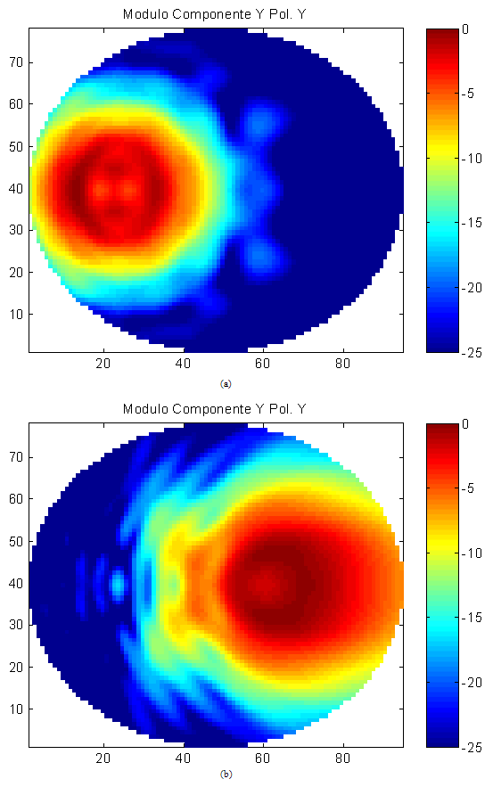 | Figure 6. Module of the incident field for 5º beam deviation on sub-reflectarray (a) and for -8º beam deviation on sub-reflectarray (b) |
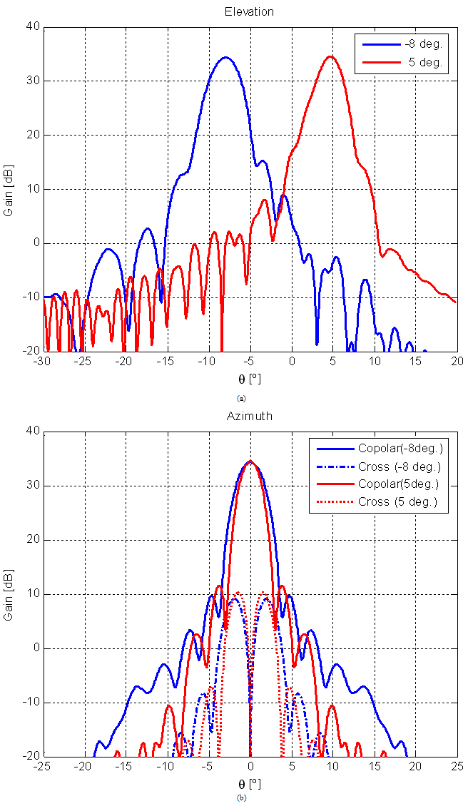 | Figure 7. Radiation patterns for the ideal phase distribution at 12 GHz (beam scan -8º, 5º) in elevation (XZ plane) and azimuth (orthogonal plane) |
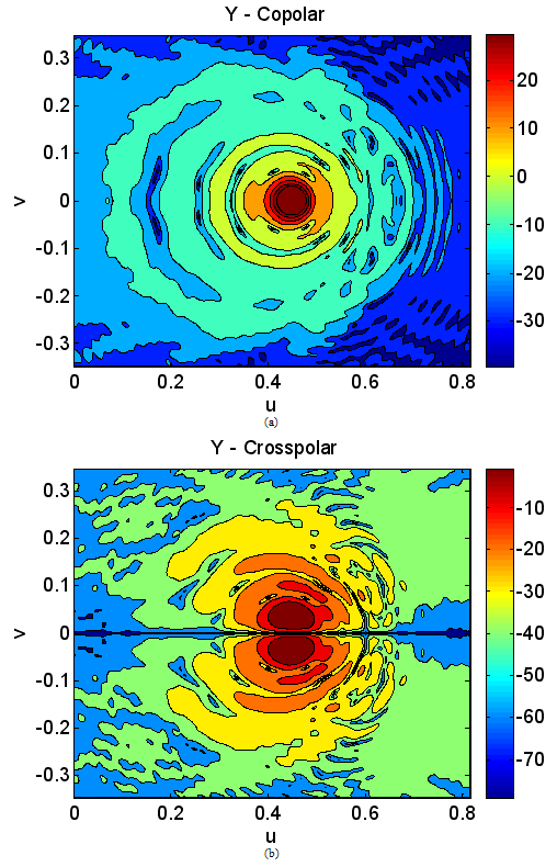 | Figure 8. Radiation patterns for -8º scan: co-polar (a) and cross-polar (b) |
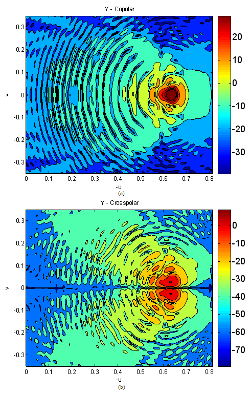 | Figure 9. Radiation patterns for 5º scan: co-polar (a) and cross-polar (b) |
3.3. Antenna Analysis Considering the Effects of the Sub-reflectarray
As a second step, a more accurate evaluation of the antenna performance is carried out, including the real effect of the sub-reflectarray elements based on aperture-coupled elements. The reflectarray subreflector is designed by adjusting the lengths of the lines for each polarization to provide the required phase distribution associated to each scan angle. Then, the required line lengths should be adjusted by MEMS switches in a real implementation. However, the effect of the MEMS devices has been neglected in this study, the antenna analyzed assuming the sub-reflectarray elements being shown in Figure 2, using the appropriate line lengths to provide the required phasing on the subreflector and considering ideal phases on the main reflectarray. Figure 10 shows the photo etching masks of the three layers of printed patches for the sub-reflectarray.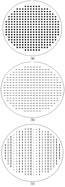 | Figure 10. Mask of the sub-reflectarray: (a) first layer of patches, (b) slots and (c) lines |
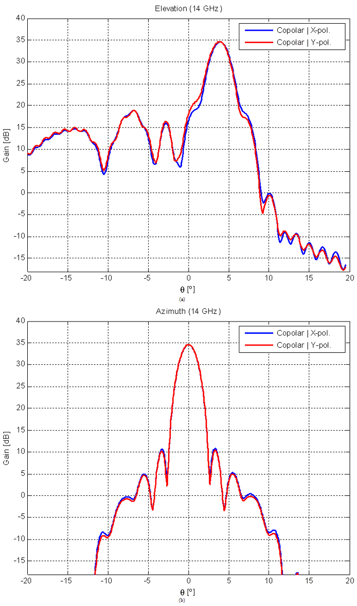
This analysis includes the variation with frequency of the reflectarray elements and provides a preliminary estimation of the antenna performance. Considering the sub- reflectarray designed for 5-deg. deflected beam at 12GHz, the antenna has been analyzed at other frequencies (10.7 and 14GHz). Figure 11 shows the radiation patterns in the main planes at 10.7GHz and at 12GHz with no distortion in azimuth and a slight distortion in elevation. Figure 12 shows the radiation pattern at 14GHz, also showing some distortions in elevation. Note that the beam is radiated at 4º, therefore a beam squint is produced. These distortions, not observed when ideal phases are used, could be improved with a better design of the aperture-coupled element for such a wide frequency band, from 10.7GHz to 14.5GHz.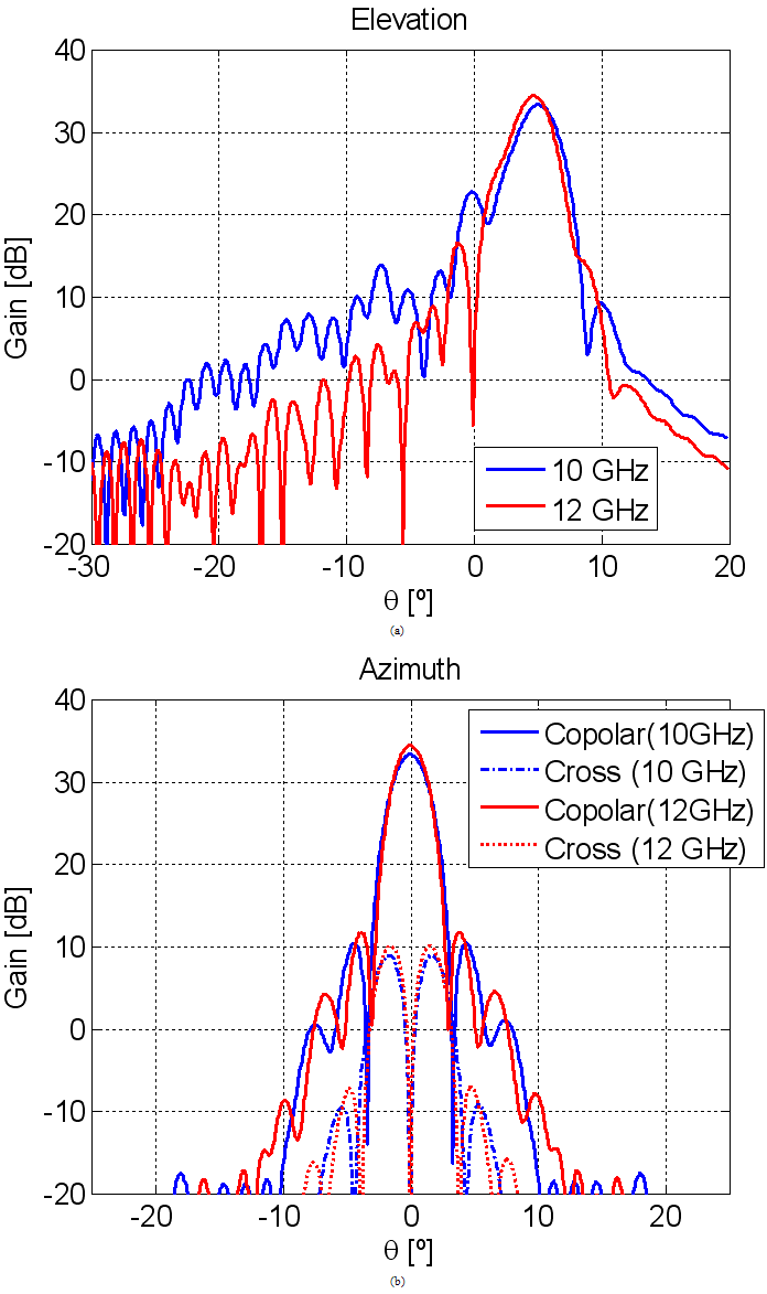 | Figure 11. Radiation pattern for the sub-reflectarray based on aperture-coupled elements designed for 5º beam scan at 10.7GHz and 12 GHz in elevation (XZ) (a) and azimuth (b) (orthogonal) planes |
 | Figure 12. Radiation pattern for the sub-reflectarray based on aperture-coupled elements designed for 5º beam scan at 14 GHz in elevation (XZ) and azimuth planes |
4. Conclusions
The proposed dual-reflectarray configuration provides phase control on both reflectarray surfaces, which can be used to improve the antenna performance for multiple beams or for beam scanning. A dual-reflectarray antenna in Ku-band has been designed to steer the beam within a range of 13 degrees (-8deg. to 5deg.). The antenna presents the capability of scanning the beam electronically by using reconfigurable elements such as pin diodes, MEMs or Liquid Crystals The preliminary simulated results obtained show acceptable beam scanning capabilities in a frequency band of more than a 10%. The radiation patterns present a good behaviour in azimuth and a little distortion in elevation. A beam squint of approximately 1 degree has been observed from 10 to 14GHz, which must be compensated in the design. The effect of the MEMS devices has been neglected, assuming the reflectarray elements with the appropriate line lengths to provide the required phasing on the subreflector. The work is in progress to account for the real characterization of the MEMS.
ACKNOWLEDGEMENTS
This work has been supported by the European Space Agency (ESA) in collaboration with RF-Microtech under the “RESKUE project” (ESA contract nº 22078/08/NL/ST) and by by Spanish Ministry of Science and Technology, under the project CICYT TEC2010-17567.
References
| [1] | M. Arrebola, L. de Haro, J. A. Encinar, ”Analysis of Dual-Reflector Antennas with Reflectarray as Subreflector”, IEEE Antennas and Propagation Magazine.,Dec. 2008, vol 50, Issue:6 pag:39-51. ISSN:1045-9243 |
| [2] | W. Hu, M. Arrebola, R. Cahill, J. A. Encinar, V. Fusco, H. Gamble, Y. Alvarez, F. Las-Heras, “ 94GHz Dual-reflector antenna with reflectarray sub-reflector”, IEEE Trans. Antennas Propag., vol. 57, no. 10, part 2, p. 3043-3050, Oct. 2009 |
| [3] | R. J. Martin and D. H. Martin, “Quasi-optical antennas for radiometric remote-sensing,”IEE Electron. & Comm. Eng. J., vol. 8, pp. 37-48, Feb. 1996 |
| [4] | L. Marcaccioli, B. Mencagli, R. Vincenti Gatti, T. Feger, T. Purtova , H. Schumacher, R. Sorrentino,"Beam steering MEMS mm-wave reflectarrays", MEMSWAVE 2006, Orvieto, Italy, June 27-30, 2006 |
| [5] | S. Ebadi, R. Vincenti Gatti and R. Sorrentino, “Linear Reflectarray Antenna Design Using 1-bit Digital Phase Shifters,” 3rd European Conference on Antennas and Propagation, EuCAP 2009, Berlin, Germany, March 2009 |
| [6] | R. Sorrentino, R. Vincenti Gatti, L. Marcaccioli, “Recent Advances in Millimetre Wave Reconfigurable Reflectarrays”, 3rd European on Conference on Antennas and Propagation, EuCAP 2009, Berlin, Germany, March 2009 |
| [7] | W. Menzel, M. Al-Tikriti, R. Leberer, “A 76 GHz multiple-beam planar reflector antenna”, EuMC, Milano, Italy, Sept. 2002, p. 977 – 980 |
| [8] | C.Tienda, M.Arrebola, J.A. Encinar and G.Toso, “Analysis of a dual-reflectarray antenna” IET Microw. Antennas Propag. 5, pp. 1636-1645, Oct. 2011 |
| [9] | C. Tienda, J.A. Encinar, S. Montori, R.Vincenti Gatti, M.Arrebola and R. Sorrentino, “Dual-Reflectarray Antennas for Bidirectional Satellite Links in Ku-band”, 5th European Conference on Antennas and Propagation, 11-15 April 2011, Rome, Italy |
| [10] | Eduardo Carrasco , Mariano Barba, José A. Encinar “Demonstration of a Switchable-Beam Reflectarray Antenna with PIN Diodes in X-Band” 33rd ESA Antenna Workshop, 18 - 21 October 2011, ESTEC, Noordwijk, The Netherlands |
| [11] | E. Carrasco, M. Barba, B. Reig, C. Dieppedale, J. A. Encinar, “Characterization of a Reflectarray Gathered Element with Electronic Control Using Ohmic RF MEMs and Patches Aperture-Coupled to a Delay Line”, IEEE Trans. Antennas Propag. (Accepted) |
| [12] | J. A. Encinar, “Design of two-layer printed reflectarrays using patches of variable size”, IEEE Trans. Antennas Propag., vol.49, p.1403-1410, Oct.2001 |
| [13] | E. Carrasco, J. A. Encinar, M. Barba, R. Vincenti, R. Sorrentino, “Dual-polarization reflectarray elements for Ku-band Tx/Rx portable terminal antenna”, EuCAP 2010, 12-16 April 2010, Barcelona, Spain |


 , p and q being the indexes of the sub-reflectarray cells that define the positions in the sub reflectarray, see (1)


 Abstract
 Reference
 Full-Text PDF
 Full-text HTML