R. Marino 1, R. Mashiah 1, H. Matzner 1, E. Levine 2
1Department of Communication Engineering, HIT – Holon Institute of Technology, Holon 58102, Israel
2AFEKA College of Engineering, Tel Aviv 69107, Israel
Correspondence to: H. Matzner , Department of Communication Engineering, HIT – Holon Institute of Technology, Holon 58102, Israel.
| Email: |  |
Copyright © 2012 Scientific & Academic Publishing. All Rights Reserved.
Abstract
A horn antenna fed by a linear array of 4 H-plane coupled rectangular waveguides is presented. The antenna was simulated, constructed and measured. The gain of this horn is higher by more than 3 dB than the gain of conventional horn with the same height. Good agreement between simulation and measurement was achieved.
Keywords:
Waveguide array, Horn antenna, High gain antenna
Cite this paper:
R. Marino , R. Mashiah , H. Matzner , E. Levine , "Investigation of a Multi-Waveguide Fed Horn Antenna", Journal of Wireless Networking and Communications, Vol. 2 No. 1, 2012, pp. 5-8. doi: 10.5923/j.jwnc.20120201.02.
1. Introduction
High gain, high power, flat antennas are needed for many applications, especially as airborne radar antennas. Slot antennas[1] can be used for these applications, however their bandwidth is small. Another alternative is the box-horn array [2-3], where the grating lobe is suppressed by the null of the box-horn. A linear array of pyramidal horns with a slant polarization is proposed by[4]. Here we propose a simple, relatively flat antenna, which is a compromise between a conventional horn antenna and a waveguide array, which can be designed for high gain, high power, low sidelobe level, and scan ability.The structure of the paper is as follows: in chapter 2 we describe the geometry of the antenna. Chapter 3 presents simulation results, and a gain comparison between the proposed antenna and a conventional horn antenna, In chapter 4 measured results are shown. Finally chapter 5 is devoted to conclusions and discussions.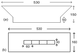 | Figure 1. (a) Side view of the antenna. (b) Upper view of the antenna |
2. Geometry
2.1. Geometry of the Proposed Antenna
Side view and upper view of the antenna are shown in fig. 1(a) and 1(b) respectively. The sizes are given in mm. The thickness of the waveguides and of the horn sides are 1 mm.The inner dimensions of the waveguides are 60 x 30 mm, and the aperture of the horn is 530 x 160 mm. The height of the horn surface is 100 mm and the length of the input waveguides is 50 mm.
3. Simulation
3.1. Simulation of the Proposed Antenna
The simulated antenna scheme is shown in fig. 2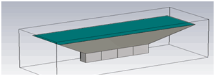 | Figure 2. A scheme of the proposed antenna |
The scattering parameters of the antenna are shown in fig. 3.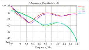 | Figure 3. S-parameters of the proposed antenna. The red and magenta lines are for S11 and S22, and the green and turquoise lines are for S21 and S23 |
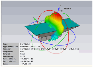 | Figure 4. A 3-dimensional pattern at 3.75 GHz |
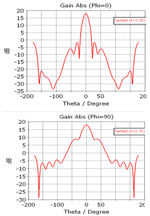 | Figure 5. (a) Simulated H-plane radiation cut at 3.75 GHz, (b) Simulated E-plane radiation cut at 3.75 GHz |
It is shown that the return losses at the ports are low, as well as the mutual coupling between neighbor ports, where port 1 is a side port and port 2 is next to port 1. A 3- dimensional radiation plot at 3.75 GHz is shown in figure 4, where the relative voltage weights are (0.7:1:1:0.7) with equal phases, for getting approximately 20 dB sidelobe level. E-plane and H-plane patterns at 3.75 GHz are shown in fig. 5. A summary of the radiation pattern results is given in table 1.| Table 1. Radiation Pattern Results of the Proposed Antenna |
| | f (GHz) | Gain(dB) | E-plane BW | H-plane BW | | 3 | 16.1 | 34.8o | 21.2o | | 3.75 | 17.9 | 26.5o | 17.5o | | 4.5 | 18.7 | 25.5o | 13.8o |
|
|
3.2. Simulated Gain Comparison
A comparison between the gains of the proposed antenna, optimized to maximal gain at 3.75 GHz, with aperture dimensions a1 = 406 mm, b1 = 156 mm, and the gain of a conventional horn, optimized to maximal gain at 3.75 GHz, with aperture dimensions a1 = 163 mm, b1 = 160 mm, is shown in figure 6. In both cases the height of the horn surfaces is 100 mm.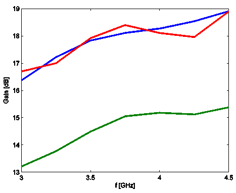 | Figure 6. Comparison between the gain of the proposed antenna and the gain of a conventional horn antenna. The blue line is for the proposed antenna, the red line is for the proposed antenna optimized to maximal gain at 3.75 GHz, and the green line is for a conventional horn optimized to maximal gain at 3.75 GHz |
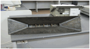 | Figure 7. A picture of the proposed antenna |
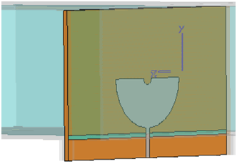 | Figure 8. The simulated U-shaped transition element |
4. Measurement
A picture of the proposed antenna is shown in fig. 7. The antenna is fed by an external 1:4 divider, where the simulated U-shaped transitions inside each waveguide are shown in fig. 8.The measured return loss of the antenna is shown in fig. 9.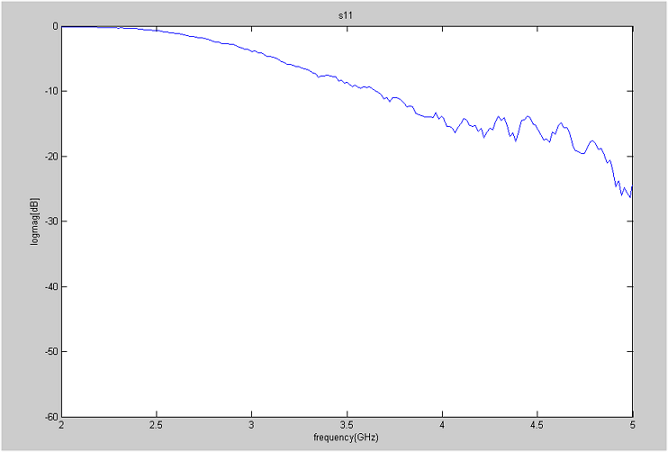 | Figure 9. Measured return loss of the antenna |
And the coupling between elements is shown in figure 10.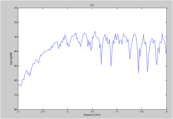 | Figure 10. Measured coupling between two antenna feed elements |
The measured H-plane radiation pattern of the antenna is shown in fig. 11 and the measured E-plane radiation pattern of the antenna is shown in fig. 12.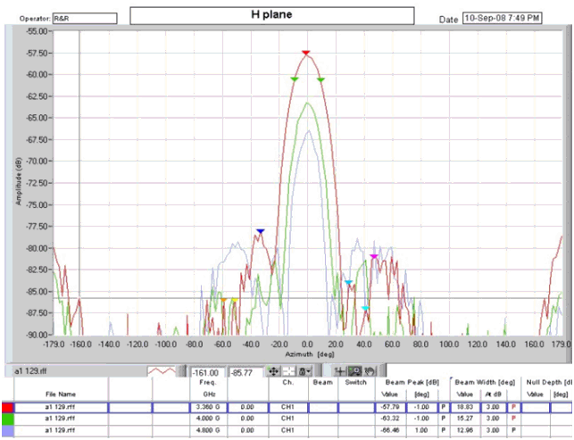 | Figure 11. Measured H-plane radiation cut of the antenna. Red line is for 3.3 GHz, green line is for 4 GHz, and magenta line is for 4.8 GHz |
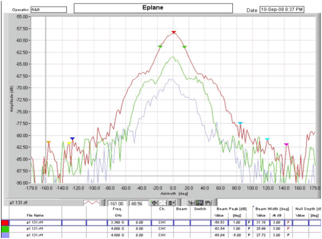 | Figure 12. Measured E-plane radiation cut of the antenna. Red line is for 3.3 GHz, green line is for 4 GHz, and magenta line is for 4.8 GHz |
The measured gain of the antenna was 16.5 dBi at 3.75 GHz. A comparison between simulated and measured results is presented in table 2| Table 2. Comparison between Measurement and Simulation (@3.75GHz) |
| | Parameter | Measurement | Simulation | | BW, SWR = 2 | 3.5 – 4.8 GHz | 2.7 – 4.8 GHz | | BW (Coupling < 20 dB) | 2.7 – 4.8 GHz | 3 – 4.8 GHz | | E-plane (degrees) | 27o | 31o | | H-plane (degrees) | 18o | 17o | | SLL (dB) | -20 | -20 | | Gain (dBi) | 16.5 | 18 |
|
|
5. Conclusions
A horn antenna fed by 4 H-plane coupled rectangular waveguides was simulated and measured. It is seen that the agreement between simulations and measurements is good. This type of antennas can be used as high gain, high power, flat antennas, and can be used also for calibration. The waveguide array can be chosen as a linear or two- dimensional array, hence a great advantage here is the flexibility in the dimensions of the antenna. However, an efficient and compact build-in divider is required.
References
| [1] | R. S. Elliott, Antenna Theory and Design, pp. 88–91,. Prentice-Hall, 1981 |
| [2] | T. Sehm, A. Lehto and A. V. Raisanen, A High-gain 58 GHz Box-horn Array Antenna with Suppressed Grating Lobes, IEEE Trans. Ant. And Propagat., Vol. 47., no. 7, 1999, 1125-1130 |
| [3] | T. Sehm, A. Lehto and A. V. Raisanen, A Large Planar 39 GHz Box-horn Antenna Array of Waveguide Horns, IEEE Trans. Ant. And Propagat., Vol. 46., no. 8, 1999, 1189-1193 |
| [4] | F. F. Dubrovka, S. Martynyuk, Y. Stepanenko, Ultra Wideband Linear Horn Array Antenna with Slant Polarization, 5th International Conference on Antenna Theory and Techniques, 2005, 283 – 286 |


 Abstract
 Reference
 Full-Text PDF
 Full-Text HTML