-
Paper Information
- Previous Paper
- Paper Submission
-
Journal Information
- About This Journal
- Editorial Board
- Current Issue
- Archive
- Author Guidelines
- Contact Us
Journal of Wireless Networking and Communications
p-ISSN: 2167-7328 e-ISSN: 2167-7336
2011; 1(1): 16-22
doi: 10.5923/j.jwnc.20110101.03
Modified Anti-Binary Collision Protocol (MABS) of Radio Frequency Identification (RFID) System
 Abstract
 Reference
 Full-Text PDF
 Full-Text HTML
Mohamed Mostafa Abd Allah 1, 2
1Minia University, Faculty of Engineering, Department of Electrical, Communications and Electronics section, Egypt
2Royal Commission, Yanbu Industrial Collage, EIET Department , Yanbu, KSA
Correspondence to: Mohamed Mostafa Abd Allah , Minia University, Faculty of Engineering, Department of Electrical, Communications and Electronics section, Egypt.
| Email: |  |
Copyright © 2012 Scientific & Academic Publishing. All Rights Reserved.
This paper introduces a modified version of anti-binary collision algorithm. The proposed method enhances data collision problems done among multiple tags in the range of the RFID reader's action. The proposed algorithm is called (MABS). It is one blocking protocol, based on Adaptive binary splitting protocol. MABS not only inherits the essence of ABS which uses the information of recognized tags obtained from the last process of tag identification, but also adopts a blocking technique which prevents recognized tags from being collided by unrecognized tags. Finally, the simulation results show that MABS outperforms ABS.
Keywords: Anti-Collision, Command Controller, Time Slot, RFID
Cite this paper: Mohamed Mostafa Abd Allah , "Modified Anti-Binary Collision Protocol (MABS) of Radio Frequency Identification (RFID) System", Journal of Wireless Networking and Communications, Vol. 1 No. 1, 2011, pp. 16-22. doi: 10.5923/j.jwnc.20110101.03.
Article Outline
1. Introduction
- Radio Frequency Identification (RFID) systems use radio frequency to identify, locate and track people, assets and animals. Passive RFID systems are composed of three components – a reader (interrogator), passive tag and host computer. The tag is composed of an antenna coil and a silicon chip that includes basic modulation circuitry and nonvolatile memory. The tag is energized by a time-varying electromagnetic radio frequency (RF) wave that is transmitted by the reader. This RF signal is called a carrier signal. When the RF field passes through an antenna coil, there is an AC voltage generated across the coil. This voltage is rectified to result in DC voltage for the device operation. The device becomes functional when the DC voltage reaches a certain level. The information stored in the device is transferred to the reader by reflecting, or loading, the reader’s carrier. This is often called backscattering. By detecting the backscattering signal, the information stored in the device can be fully identified. In many existing applications, a single-read RFID tag is sufficient and even necessary: animal tagging and access control are examples. However, in a growing number of new applications, the simultaneous reading of several tags in the same RF field is absolutely critical: library books, airline baggage, garment and retail applications are a few examples. In order to read multiple tags simultaneously, both the tag and reader must be designed to detect the condition that more than one tag isactive. Otherwise, the tags will all backscatter the carrier at the same time and the amplitude-modulated waveforms would be garbled. This is referred to as a collision. No data would be transferred to the reader. The tag/reader interface is similar to a serial bus, even though the “bus” travels through the air. In a wired serial bus application, arbitration is necessary to prevent bus contention. The RFID interface also requires arbitration so that only one tag transmits data over the “bus” at one time. A number of different methods are in use and in development today for preventing collisions; most are patented or patent pending. Yet, all are related to making sure that only one tag “talks” (backscatters) at any one time. One kind of RFID anti-collision protocols is the tree-based protocols. Tree-based protocols, such as the binary tree protocol (BT)[2, 3, 4] and the query tree protocol (QT)[5, 6, 7] based on the tree protocol[8, 9], continuously split a set of tags into two subsets until each set has only one tag. Myung et al.[10, 11, 12] proposed twoanti-collision protocols, the adaptive query splitting protocol (AQS) and the adaptive binary splitting protocol (ABS), which were modified from QT and BT, respectively. Using the information obtained from the last frame, AQS and ABS successfully reduce the collisions caused by staying tags. From the previous studies[12], ABS has the shorter identification delay than AQS. However, AQS and ABS cannot prevent staying tags from being collided by arriving tags that newly appear in the current frame and were not recognized in the last frame. Thus, we propose one blocking protocol based on ABS. This new protocol is the blocking ABS protocol (MABS ) which adopts the blocking technique to prohibit arriving tags from colliding with staying tags. The rest of this paper is organized as follows. Section II briefly describes BT and ABS. Section III formally presents the concept, operation, and example of MABS . Section IV provides the simulation results to verify the superiority of MABS over ABS. The conclusions are presented in Section V.
2. Anti-Collision Parameters
- In most cases, as shown at figure 1, anti-collision dependant on some factors such as, communication protocol, frequency read range (communication distance between reader and tag), RF power level, reader’s receiving sensitivity, size of antenna, data rate, etc.
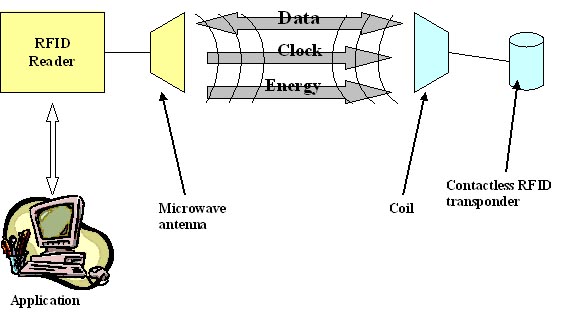 | Figure 1. Typical communication procedure |
2.1. Reader, Interrogator
- RFID readers are used to activate passive tags with RF energy and to extract information from the tag. For this function, the reader includes RF transmission, receiving and data decoding sections. In addition, the reader often includes a serial communication (RS-232, USB, etc.) capability to communicate with a host computer. Depending on the complexity and purpose of applications, the reader’s price range can vary from ten dollars to a few thousand dollars worth of components and packaging. The RF transmission section includes an RF carrier generator, antenna and a tuning circuit. The antenna and its tuning circuit must be properly designed and tuned for the best performance. Data decoding for the received signal is accomplished using a microcontroller. The firmware algorithm in themicrocontroller is written in such a way to transmit the RF signal, decode the incoming data and communicate with the host computer.Typically, the reader is a read-only device, while the reader for a read and write device is often called interrogator. Unlike the reader for a read-only device, the interrogator uses command pulses to communicate with a tag for reading and writing data.
2.2. Tags & Antenna Circuit
- Tags are the second parameter that anti-collision protocol depends on. It consists of a silicon device and antenna circuit. The purpose of the antenna circuit is to induce an energizing signal and to send a modulated RF signal. The read range of a tag as shown at figure 2 is largely depends upon the antenna circuit and size. The antenna circuit is made of a LC resonant circuit or E-field dipole antenna, depending on the carrier frequency. The LC resonant circuit is used for frequencies of less than 100 MHz. In this frequency band, the communication between the reader and tag takes place with magnetic coupling between the two antennas through the magnetic field. An antenna utilizing inductive coupling is often called a magnetic dipole antenna. The antenna circuits must be designed in such a way to maximize the magnetic coupling between them. This can be achieved with the following parameters: a) LC circuit must be tuned to the carrier frequency of the reader. b) Maximize Q of the tuned circuit. c) Maximize antenna size within physical limit of application requirement.
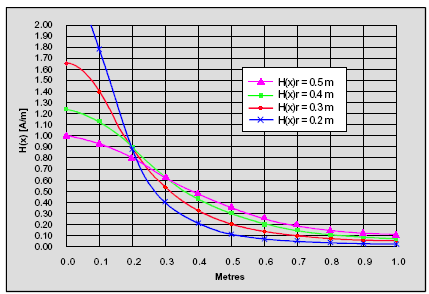 | Figure 2. Field Densities for different sized antennas vs. distance |
2.3. Read/Write Range
- Read/write range is the communication distance between the reader (interrogator) and tag. Specifically, the read range is the maximum distance to read data out from the tag and the write range is the maximum distance to write data from interrogator to the tag.The read/write range is related to:(1) Electromagnetic coupling of the reader (interrogator) and tag antennas(2) RF Output power level of reader (interrogator)(3) Carrier frequency bands(4) Power consumption of the deviceThe electromagnetic coupling of the reader and tag antennas increases using a similar size of antenna with high Q in both sides. The read range is improved by increasing the carrier frequency. This is due to the gain in the radiation efficiency of the antenna as the frequency increases. However, the disadvantage of high frequency (900 MHz to 2.4 GHz) application is shallow skin depth and narrower antenna beam width. These cause less penetration and more directional problems, respectively. Low frequency application, on the other hand, has an advantage in the penetration and directional, but a disadvantage in the antenna performance. Read range increases by reducing the current consumption in the silicon device. This is because the LC antenna circuit couples less energy from the reader at further distances. A lower power device can make use of less energy for the operation.
2.4. System Handshake
- The reader continuously transmits an RF signal while always watching for modulated backscattering signal. Once the tag has received sufficient energy to operate correctly, it begins clocking its data to a modulation transistor, which is connected across the antenna circuit.The tag’s modulation transistor shorts the antenna circuit, sequentially corresponding to the data which is being clocked out of the memory array. Shorting and releasing the antenna circuit according to the modulation data causes amplitude fluctuation of antenna voltage across the antenna circuit. The reader detects the amplitude variation of the tag and uses a peak-detector to extract the modulation data.
2.4.1. Typical Communication Procedure
- The interrogator sends a command to initiatecom-munication with tags in the field. The RF carrier is also used for energizing the device. Once the tag has received sufficient energy and command, it responds back with its ID for acknowledgment. The interrogator now knows which tag is in the field. The interrogator sends a command to the identified tag for instructions: processing (read or write) or Sleep. If the tag receives processing and reading commands, it transmits a specified block data and waits for the next command. If the tag receives processing and writing commands along with block data, it writes the block data into the specified memory block, and transmits the written block data for verification. After the processing, the interrogator sends an End command to send the tag into the Sleep (“silent”) mode. If the device receives an End command after processing, it sends an acknowledgement (8-bitpreamble) and stays in Sleep mode. During the Sleep mode, the device remains in non-modulating (detuned) condition as long as it remains in the power-up. The interrogator is now looking for the next tag for processing, establishes a handshake and repeats the processing.
3. Anti-Collision
- A general RFID system is comprised of a reader and several tags. The reader recognizes objects through wireless communications with tags attached to objects and each tag carries a unique ID[1]. The reader must be able to recognize tags as soon as possible in order to accelerate business activities. However, simultaneous signals transmitted by tags collide with each other, since they share the same wireless channel. Due to collisions, the reader cannot recognize tags immediately and will request the tags to retransmit their IDs thereby resulting in bandwidth waste and increase of identification delay. Therefore, an efficient anti-collision protocol is required to reduce collisions and achieve a faster identification. Figure 3 shows examples of anti-collision problems done on RFID application. In many RFID applications, the reader may repeatedly identify existing tags. Thus, when there are a lot of tags which don’t leave the reader’s range, called staying tags, then if an anti-collision protocol can retain information obtained from the last process of tag identification, i.e., last frame, the reader can skip many collisions and quickly re-identify the staying tags in the current frame.
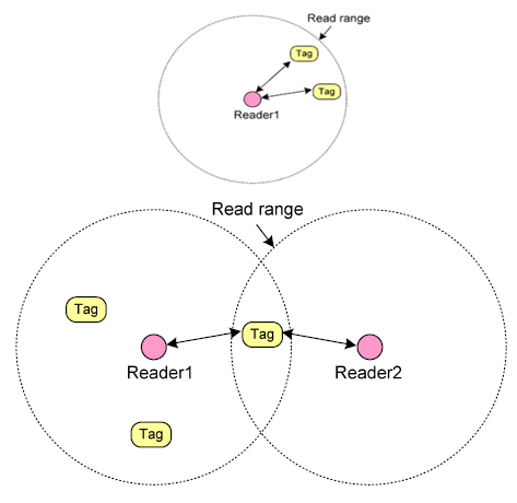 | Figure 3. Examples of Anti collision problem in RFID |
3.1. Anti-Collision Algorithm Description
- The proposed anti-collision algorithm is based on time division multiplexing of tag responses. Each device is allowed to communicate with the Interrogator in its time slot only. When not in its assigned time slot, the device remains in a non modulating condition. This enables the Interrogator to communicate with other devices in the same Interrogator field with fewer chances of data collision. If a tag dwells within the reader’s identification range, it is able to communicate with the reader directly. Tags transmit their own ID and then the reader detects collision. The reader always informs all tags whether or not the tag-to-reader signals collide. When tag-to-reader signals lead to collision, the colliding tags randomly select a binary number, 0 or 1. Based on this selected number, a group of the colliding tags is split into two subgroups. By continuing this split until tags enable to transmit without collision, the reader can recognize all the tags. Since each tag gets an exclusive time for transmission, proposed algorithm can reduce the number of collisions of the tag-to-reader signals and identify tags fast. In addition, it could accomplishes fast re-assigning the collision-free timeslots to each of the tags even though a set of tags which inhabit in the vicinity of the reader becomes different.
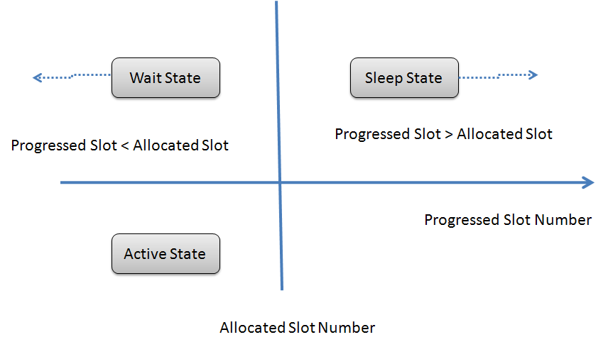 | Figure 4. three state of Tag |
3.2. Anti-Collision Splitting Terminologies
- This section includes the Anti-collision/command controller, the time slot generator and the time slot counter. We define a frame as the duration from the moment a reader begins recognizing all tags within its reading range to the time it finishes all recognitions. Let fi denote the i-th frame. The reader can adaptively decide the length of a frame with the commands informing tags of beginning and terminating the frame. The reader can change the ending point of a frame at any time. The frame consists of timeslots which are certain time periods. In each timeslot, tags transmit their IDs and the reader receives the tag-to-reader signals. Let ci, j denote the j-th slot in the i-th frame. According to the number of signals transmitted in a timeslot, we can categorize the timeslots and tag statues as followsŸ Empty timeslot: No signals are transmitted by tags in a timeslot.Ÿ Readable timeslot: Only one tag transmits its ID and is successfully recognized by the reader. Since the communication protocol does not terminate a frame till all tags are recognized, the number of readable timeslot equals to the number of tags recognized by the reader.Ÿ Collision timeslot: More than one tag transmits and then the tag-to-reader signals collide. The reader is unable to recognize any tags.Ÿ Staying tag: The tag exists in fi-1 and also in fi.Ÿ Arriving tag: The tag does not exist in fi-1, but exists in fi.Ÿ Leaving tag: The tag exists in fi-1, but does not exist in fi.Moreover, let Ti represent a set of tags existing in fi, and |Ti| is the number of these tags. The notation[x] signifies ceiling function of x.
3.3. Anti-Collision Splitting Protocol
- The reader, in the end of a timeslot, sends a feedback informing all the tags of the type of the current timeslot. After receiving the feedback, tags operate the timeslot allocation procedure and the empty timeslot elimination procedure so that a timeslot will carry only one tag’s signal. To realize the fast identification, ABS holds down empty and collisional timeslots. The tag maintains values of a progressed-slot number and an allocated-slot number. The progressed-slot number represents the number of timeslots passed in a frame and is initialized with 0 at the beginning of a frame. The progressed-slot numbers of all the tags are always equal. To put it concretely, the value of the progressed-slot number is not increased in every timeslot and is only increased by 1 in the readable timeslot, i.e., when a tag is successfully identified. The allocated-slot number signifies the sequence that the tag can access a channel to transmit. In other words, the tags of which the allocated-slot number is the same value as the progressed-slot number can try to transmit at the beginning of the timeslot. As shown in Fig. 4, the tag has one of three states as follows:Ÿ Wait state: The tag has the allocated-slot number greater than the progressed-slot number. It does not transmit any signal and waits for its turn.Ÿ Active state: The tag has the allocated-slot number equal to the progressed-slot number and tries to transmit its own ID.Ÿ Sleep state: The tag has the allocated-slot number less than the progressed-slot number. Since the tag has already recognized in the ongoing frame, it does not transmit any signal until the completion of the frame.As the timeslot allocation procedure and the empty timeslot elimination procedure of ABS change the progressed-slot number and the allocated-slot number, the tag takes possession of the favourable timeslot to transmit. In the collision timeslot, the colliding tags, i.e., the tags of the active state, add a randomly selected binary number (0 or 1) to the allocated-slot number. Therefore, the active tags which select 1 convert their state into the wait state. The tags in the wait state, when collision occurs, increase the allocated-slot number. The tags in the wait state, when the received feedback points that any signals are not carried in the current timeslot, decrease the allocated slot number. The detailed description and the example of procedures are given in next Sections. After all, each of allocated-slot numbers is assigned to only one tag. There exist no ownerless allocated-slot numbers less than any allocated-slot number which a certain tag owns. The tags preserve the allocated-slot number at the beginning of the next frame and the timeslot allocation procedure and the empty timeslot elimination procedure re-arrange allocated-slot numbers fast. Consequently, tags are fast recognized in next frames.
3.4. Adaptive Binary Splitting Protocol (ABS)
- Adaptive binary splitting protocol (ABS) which was modified from Binary tree protocol (BT), preserves the tags’ identification order obtained from the last frame in order to avoid unnecessary collisions and idle cycles generated from identifying the staying tags in the current frame. Each tag owns two counters, a Progressed Slot Counter (PSC) and an Allocated Slot Counter (ASC) where PSC signifies the number of tags recognized by the reader in the ongoing frame, and ASC records the cycle in which the tag can transmit its ID. The reader also owns two counters, a Progressed Slot Counter (PSC) and a Terminated Slot Counter (TSC) where TSC represents the largest ASC in order to terminate a frame. All tags and the reader have the same value of PSC during the identification process, and all PSCs are initialized to 0 at the beginning of each frame. When ASC is equal to PSC, the tag transmits its ID. On the other hand, when ASC is less than PSC, the tag does not respond any more until the end of the ongoing frame, since it has been recognized already. According to the reader’s feedback telling what happens at the last cycle, the tag adjusts PSC and ASC during the current cycle as follows. Tags add 1 to PSC (Readable), Tag k decreases ASCk by 1, if ASCk>PSC (Idle), tag k, which is involved in this collision, i.e., ASCk=PSC, randomly generates a binary number and adds this number to its ASCk.( Collision), and the tag k, which is not involved in this collision, i.e., ASCk>PSC, adds 1 to its ASCk.
| ||||||||||||||||||||||||||||||||||||||||||||||||||||||||||||||||||||||||||||||||
4. Proposed (MABS) Modified ABS Protocol
- ABS can avoid collisions among staying tags, but it cannot prevent arriving tags from colliding with staying tags. Hence, the main difference between ABS and MABS is that the former is a non-blocking protocol while the latter is a blocking protocol. MABS first uses the reader’s ID to distinguish the staying tags from the arriving tags, and then demands all arriving tags to change their ASCs to a random number ranging from TSC+1 to an modified TSC, i.e., TSCMOD. As we know, the optimal allocated cycle size for n tags in BT is 0.88n[13]. Thus, MABS first estimates the number of arriving tags to decide the value of TSCMOD. MABS not only avoids collisions between the staying tags, which use ASCs from 0 to TSC, but also prevents the staying tags from being collided with the arriving tags, which use ASCs between TSC+1 and TSCMOD. In MABS, the collisions between arriving tags are the only occasions when the collision cycles occur.
4.1. Modified ABS Protocol (MABS) Procedures
- Like ABS, MABS also lets each tag have two counters, PSC and ASC, and the reader have two counters, PSC and TSC. These counters are operated as ABS. To be a blocking protocol, MABS extra maintains four sets of parameters rRID, tRID, NewCount, and TSCMOD. Each tag uses the tRID to memorize its reader’s ID in order to know where it is. The reader stores its ID to rRID. The reader adopts NewCount counter to sum up the number of arriving tags in the ongoing frame for estimating the number of arriving tags in the next frame.TSCMOD: TSCMOD+1 represents the number of initially allocated cycles for all tags at the start of each frame. That is, the allocated cycle numbers are from 0 to TSCMOD, where 0~TSC is used by staying tags and TSC+1~TSCMOD is used by arriving tags. In MABS, TSCMOD is set to be equal to TSC plus 0.88 multiplying the exponential average of NewCount. At the start of a frame, the reader initially transmits the start command with TSC, TSCMOD and rRID to all the tags. The tag checks if its tRID matches the rRID sent by the reader. If they are different, the tag interprets itself as an arriving tag. Hence, the tag changes its ASC to a random number from TSC+1 to TSCMOD and then sets its tRID to rRID. In order to provide enough cycles for arriving tags to avoid causing unnecessary collisions, the reader remembers the number of arriving tags in the last frame, i.e., NewCount, and then adopts its exponential average to estimate the number of arriving tags in the current frame, NewEst, by using NewEst = z × NewEst + (1-z) × NewCount. The factor z is used to weight the last estimation and the exact number of arriving tags in the last frame. Then TSCMOD is set as the last TSP plus 0.88x NewEst. After setting TSCMOD, the reader resets NewCount to 0 for counting the number of arriving tags in the ongoing frame. On the other hand, if tRID equals rRID, the tag interprets itself as a staying tag and already has an appropriate ASC determined in the last frame. For each cycle, the tag’s manipulation of PSC and ASC is the same as that in ABS. After giving TSC, TSCMOD and rRID to all the tags, the reader is able to initially recognize the staying tags and then the arriving tags since the staying tags have ASC ranging from 0 to TSC while the arriving tags have ASC ranging from TSC+1 to TSCMOD. At each cycle, the manipulation of PSC and TSC in the reader is the same as that for ABS. For terminating a frame, the reader changes TSC to TSCMOD, and transmits the command terminating the ongoing frame to all the tags when TSC<PSC. Table 1 shows an example of MABS in the i+1 frame. At the beginning of the frame fi, the reader initially gives a start command with TSC=0, TSCMOD=0 and rRID to all the tags. Under the assumption that no tag exists in fi-1, in fi all tags within the reader are regarded as arriving tags, since all of their tRIDs do not match the rRID. After fi, tags A, B, C, and D, remember that ASCA=0, ASCB=1, ASCC=2, and ASCD=3, respectively, and the reader memorizes TSC=3. In MABS, the reader further counts the number of arriving tags in fi, i.e., NewCount=4. The procedure of fi+1 is shown in Table 1 At the beginning of fi+1, the reader initially gives a start command with TSC=3, TSCMOD=5 and rRID to all the tags, where TSCMOD is equal to 3 + ⎢⎡0.88 × (0.5 × 0 + 0.5 × 4)⎤⎥ under the assumption that the parameter z = 0.5 . When tags A, C, D, E, and F, receive the start command, they first check if their tRIDs match the rRID. Here, tags A, C, and D, have the same value of tRID and rRID and thus, they use their individual ASCs determined in fi. Tags E and F have different values of tRID and rRID, and set their ASCs to a random number from TSC+1 to TSCMOD, i.e., 4 to 5. Suppose tag D selects ASC=4 and tag E chooses ASC=5. As soon as each tag chooses its ASC, MABS can recognize them in the increasing order of ASCs. Thus, tags A, C, D, E, and F, are able to successfully transmit their IDs when PSC=ASCA=0, PSC=ASCC=1, PSC=ASCD=2,PSC=ASCE=3, and PSC=ASCF=4, respectively.
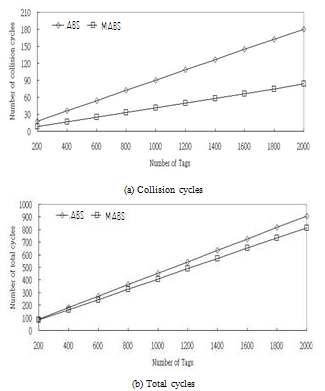 | Figure 5. Simulation results according to the number of tags N |
5. Performance Evaluation
- We evaluate the performance of MABS and compare it with ABS. BT is not considered in the comparison because it has a poor performance[10, 11, 12] and causes the lines of the other three methods in the figures to be distinguished with more difficulty when viewing. The number of total cycles (collision cycles, idle cycles and readable cycles ) are considered to evaluate the efficiency of the tag identification. We measure the number of collisions between tag-to-reader signals. The reader cannot recognize any tag during the collision cycles and hence, a collision not only postpones the tag identification, but also increases the tag’s power consumption. The reader cannot identify any tag at an idle cycle, so that the number of idle cycles is another significant factor for prolonging the identification delay. The number of total cycles signifies the identification delay in recognizing all tags. This value is the most critical factor in evaluating the performance of anti-collision protocols. We conduct a realistic simulation where the tags move within an area. In this simulation, MABS uses an exponential average to estimate the number of arriving tags with the default weight factor z=0.5, unless otherwise specified. We investigate the effect of some parameters: the number of tags, the tag mobility, and the tag stationary probability, on the performance of the proposed anti-collision protocol. Finally, we investigate the influence of z on the performance of MABS.
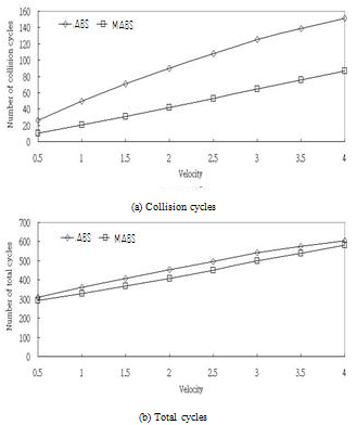 | Figure 6. The simulation results according to the tag velocity v |
6. Conclusions
- A collision caused by the tags transmitting their signals simultaneously is a major factor in postponing the tag identification in RFID systems. We proposed one novel tree-based anti-collision protocol, MABS. MABS not only exploits information obtained from the last frame to prevent collisions between staying tags, but also blocks arriving tags in order to avoid that they collide with staying tags. We conducted several simulations. In a realistic environment, although BA has more idle cycles than ABS, it reduces even more collision cycles than ABS. Therefore, MABS always surpasses ABS, regardless of the number of tags, the tag velocity, and the stationary probability.