-
Paper Information
- Paper Submission
-
Journal Information
- About This Journal
- Editorial Board
- Current Issue
- Archive
- Author Guidelines
- Contact Us
Journal of Nuclear and Particle Physics
p-ISSN: 2167-6895 e-ISSN: 2167-6909
2021; 11(1): 7-14
doi:10.5923/j.jnpp.20211101.02
Received: Nov. 10, 2020; Accepted: Dec. 6, 2020; Published: Mar. 20, 2021

Core Neutronic Characterization of Advanced Pressurized Water Reactor
 Abstract
 Reference
 Full-Text PDF
 Full-text HTML
Hend Saad1, Moustafa Aziz1, Riham Refeat1, Hesham Mansour2
1Nuclear Safety Engineering Department, Nuclear and Radiological Regulatory Authority, 3 Ahmed El Zomor St., Nasr City, Cairo, Egypt
2Physics Department, Faculty of Science, Cairo University, Giza, Egypt
Correspondence to: Hend Saad, Nuclear Safety Engineering Department, Nuclear and Radiological Regulatory Authority, 3 Ahmed El Zomor St., Nasr City, Cairo, Egypt.
| Email: |  |
Copyright © 2021 The Author(s). Published by Scientific & Academic Publishing.
This work is licensed under the Creative Commons Attribution International License (CC BY).
http://creativecommons.org/licenses/by/4.0/

Based on design improvements and operational experience to conventional PWRs, the advanced PWR (APWR) has been attained for use as a standard large-scale plant. Developments have been made to improve the economical efficiency, safety, and reliability by various design improvements, such as reactor core enlargement and an increase in the burnup of fuel. In this paper, MCNP6 computer code is used to model the reactor core of Advanced Pressurized Water Reactor (APWR). The reactor core, consisting of 257 improved 17 x 17 fuel assemblies, has a thermal output of approximately 4451 MWt. The effective multiplication factor of the core and radial power mapping distributions are calculated and compared with the reference. The depletion of fissile materials U-235, U-238, Pu-238, Pu-239, Pu-241, and Pu-242 is determined at different Burnup steps. Kinetic parameters such as delayed neutron fractions and prompt neutron life time are determined and compared also with the reference. Good agreement is observed between the present model and the reference in all cases.
Keywords: Advanced Pressurized Water Reactor (US-APWR), Burnable poisons, Gadolinium (Gd), Burnup, and radial power distribution
Cite this paper: Hend Saad, Moustafa Aziz, Riham Refeat, Hesham Mansour, Core Neutronic Characterization of Advanced Pressurized Water Reactor, Journal of Nuclear and Particle Physics, Vol. 11 No. 1, 2021, pp. 7-14. doi: 10.5923/j.jnpp.20211101.02.
Article Outline
1. Introduction
- The Advanced Pressurized Water Reactor APWR has been developed, as a joint international cooperative development project between the Japanese PWR electric power companies, Mitsubishi Heavy Industries and Westinghouse. APWR is a generation III nuclear reactor design develop based on advanced pressurized water reactor technology [1]. Generation III nuclear reactors are essentially generation II reactors with evolutionary design improvements in several areas, namely, fuel technology, thermal efficiency, modularized construction, safety systems, and standardized design for each type. These improvements are undergone to expedite licensing, reduce the capital cost and construction time. Generation III improvements in reactor technology have aimed at a longer operational life, typically 60 years of operation. A simpler and more rugged design makes them easier to operate and less vulnerable to operational upsets. Further, it reduced possibility of core melt accidents. Higher burn-up of fuel increases it’s efficiently, and reduce the amount of waste produced. Greater use of burnable absorbers ('poisons') to extend fuel life [2]. The basic design concepts of the US-APWR are similar to those of Japanese APWR whose design has completed. Namely; the US-APWR has been developed as a large-scale version for the advanced pressurized water reactor, aiming at higher electrical outputs and improved economics [1]. US-APWR has a 4451 MWt, about 1600 MWe net, due to longer (4.3m instead of 3.7m in earlier designed PWR) fuel assemblies, higher core burnup and higher thermal efficiency (37%). It has 24-month fuel cycle. The most important requirement of a nuclear power plant is the safety, so, the US-APWR incorporates numerous technical improvements to further enhance its safety features [3-6].
2. Reactor Core Description
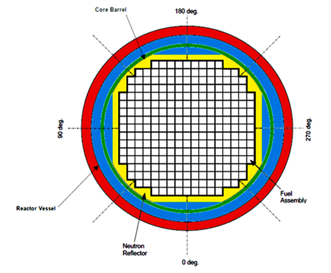
- The US-APWR core consists of 257 fuel assemblies surrounded by a stainless-steel radial neutron reflector designed to improve neutron utilization, which reduces the fuel cycle cost and significantly reduces reactor vessel irradiation compared to previous PWRs with baffle/barrel designs [1]. The 17 x 17 fuel assembly consists of 264 fuel rods, 24 guide thimble tubes, and 1 instrumentation thimble tube .The instrumentation thimble is positioned in the center of the fuel assembly to provide a location for an in-core neutron detector if the fuel assembly is located in an instrumented core position as shown in figure (1). The radial reflector, consisting of stainless steel blocks, not only reduces fuel cycle costs but also reduces the irradiation of the reactor vessel and core internals. Through installation of the radial reflector, neutron irradiation of the reactor vessel can be reduced to 1/3 that of present reactors. The US-APWR, with a low power density core, not only reduces the number of fuel assembly replacements, which improves fuel economic efficiency, but also enables the long-cycle operation of about 24 months, leading to better availability and reduction of generation costs.
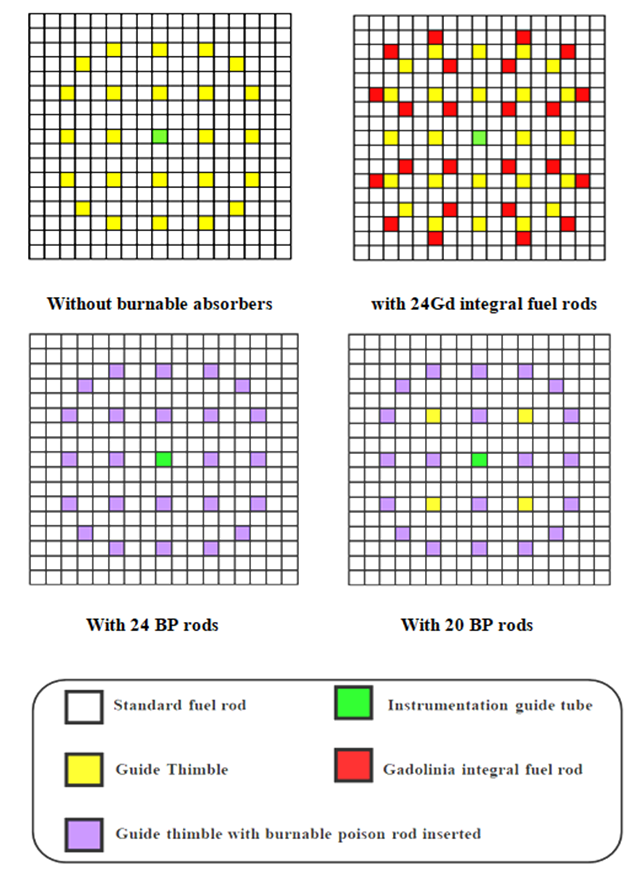 | Figure 1. Arrangement of Fuel and Burnable Poison Rods within fuel assembly (initial core) |
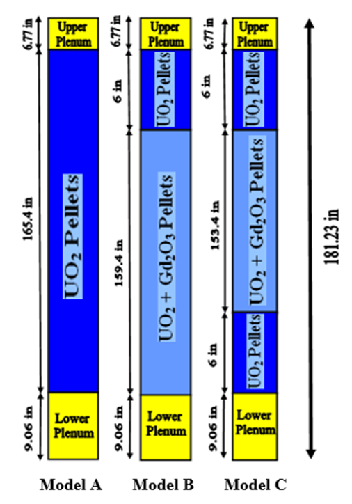 | Figure 2. Schematic View of axial composition of Fuel Rod (Dimensions in inches according to the reference) |
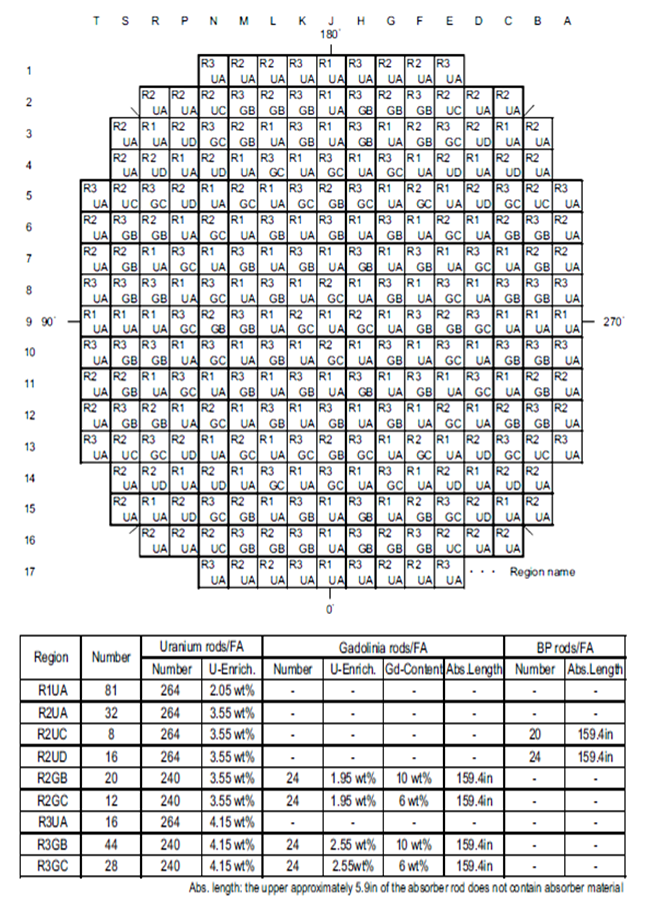 | Figure 3. Shows a typical initial core loading pattern |
3. MCNP6 Computer Core Model
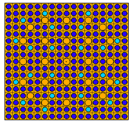
- The particle radiation transport code MCNP, which stands for Monte Carlo N Particle, is a general-purpose, continuous-energy, generalized-geometry, time-dependent, Monte Carlo radiation-transport code designed to track many particle types over broad ranges of energies. MCNP6 [10] represents the culmination of a multi-year effort to merge the MCNP5™ and MCNPX™ codes into a single product comprising all features of both. The new features include treatment of large amount of particles, inclusion of model physics options for energies above the cross-section table range, Burnup feature, and delayed particle production. [9-12]MCNP6 code [7,8] is used to simulate whole reactor core. Nine different fuel assembly batches are considered in the core design in details. Each assembly batch is characterized by different fuel enrichment, axial rods composition, number of burnable poison and rod Gadolinium content. The total core assemblies are 257 with 17 x 17 rod distributions. The core assemblies’ distributions are given in details in Figure 3. The core barrel and the pressure vessel are also included in the model. Figure 4: shows typical model for type (A) fuel assembly without burnable poison.Figure 5: shows typical (B&C) types which contain 24 Gadolinium integral fuel rods. Figure 6: shows typical model for type (A) fuel assembly with 20 burnable poisons.Figure 7: shows typical model for type (A) fuel assembly with 24 burnable poisons.Figure 8: shows Horizontal cross section view for the whole reactor core. The model includes neutron reflector, core barrel and pressure vessel.
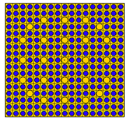 | Figure 4. An MCNP6 cross sectional view for model (A), without burnable absorbers |
 | Figure 5. An MCNP6 cross sectional view for models (B&C), with 24 Gd integral fuel rods |
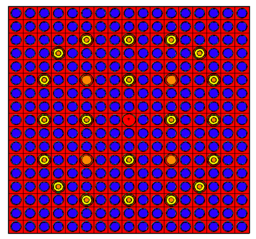 | Figure 6. An MCNP6 cross sectional view for model (A), with 20 burnable absorbers |
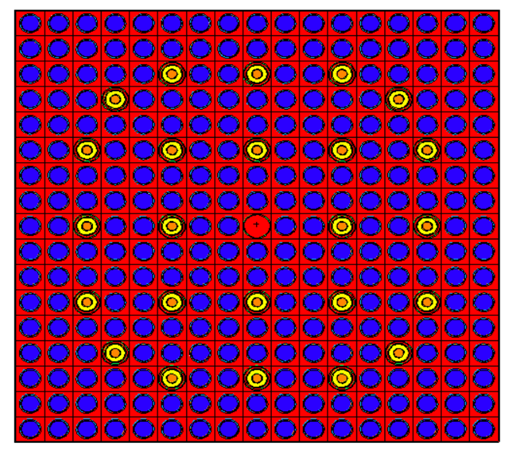 | Figure 7. An MCNP6 cross sectional view for model (A), with 24 burnable absorbers |
 | Figure 8. MCNP6 cross sectional view of radial Initial Core Fuel Loading Patterns |
4. Results and Discussion
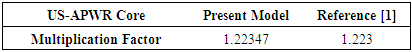
- The effective multiplication factor of the reactor is calculated for the initial core [1]. The initial conditions used: temperature of cold shutdown, without xenon (NoXe), all control rods are out (ARO), no soluble boron (zero ppm), for beginning of cycle (BOC). Using MCNP6 code and library ENDF/B-VII.1 [9] the maximum core Keff of the present work is shown in table 1. It is noticed that the difference between the present model and the reference [1] is 47pcm with estimated relative error equal to 0.00043. The result shows a good agreement. This indicated that the current version of MCNP6 and the nuclear data library used (ENDF/B-VII.1), can accurately simulate the US-APWR.
|
4.1. Radial Power Distribution
- Power distribution for typical initial core (one-eighth-core) normalized radial power distribution at hot full power, without xenon (NoXe) conditions for beginning of cycle (BOC) is shown in Figure 9. The upper value is the assembly type; the second is the power value for the present model, third for Reference, followed by difference between the present model and reference. The average difference between the present model and the reference is 0.0583 with minimum difference 0.01 and maximum difference 0.11 for two assemblies only.
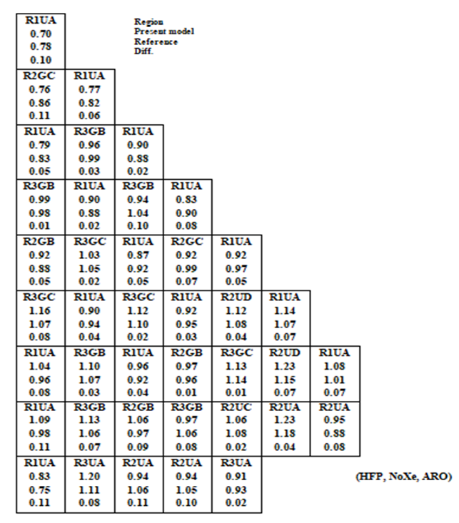 | Figure 9. Normalized Radial Power at 0 (GWD/MTU) |
4.2. Burnup Calculation
- The core is burned up to 40 (GWd/MTU). The values of the keff obtained for whole core are presented in Figure 10.
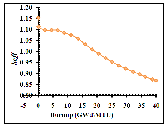 | Figure 10. Variation of keff of the core with burnup |
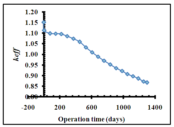 | Figure 11. keff change with time of full core |
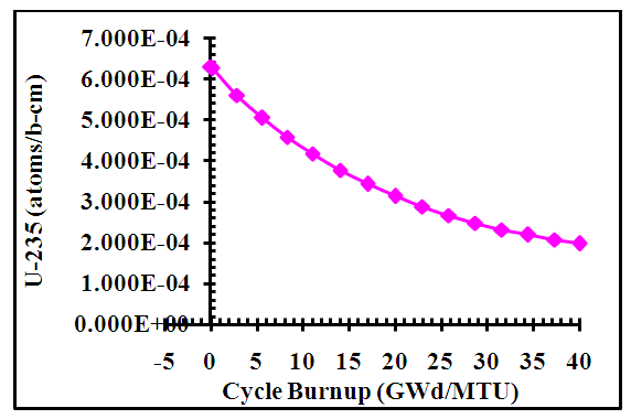 | Figure 12. 235U concentration (atoms/barn-cm) with burnup (GWd/MTU) averaged over full core |
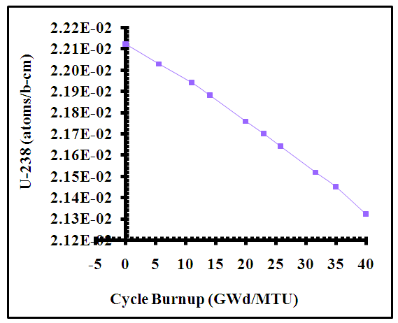 | Figure 13. 238U concentration (atoms/barn-cm) with burnup (GWd/MTU) averaged over full core |
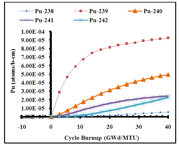 | Figure 14. Plutonium isotopes concentration (atoms/barn-cm) with burnup (GWd/MTU) over full core |
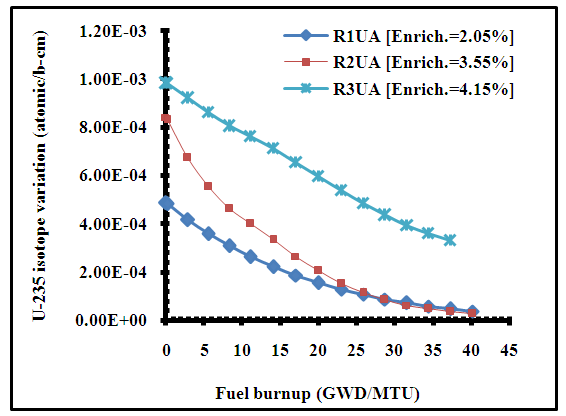 | Figure 15. 235U concentrations (atoms/barn-cm) with burnup (GWd/MTU) of three regions contain pure UO2 only in the full core |
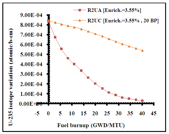 | Figure 16. 235U concentrations (atoms/barn-cm) with burnup (GWd/MTU) of two regions with and without burnable absorber rods in full core |
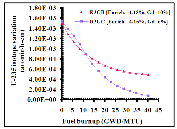 | Figure 17. 235U concentrations (atoms/barn-cm) with burnup (GWd/MTU) of two regions contain Gadolinia rods with different enrichment (10% and 6%) in full core |
|
5. Conclusions
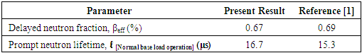
- Ø MCNP6 computer code is used to design a computer model to the reactor core; the model includes reactor core, water cooling, neutron reflector, thermal shield and pressure vessel.Ø Reactor effective multiplication factor and radial power distribution are in good agreement with the reactor design document.Ø The results indicate that the reactor could achieve a fuel cycle of 24 months for the first initial core loading.Ø Kinetic parameters such as delayed neutron fractions and prompt neutron life time are in good agreement with the reference.
Note
- 1. ZIRLOTM is a registered trademark of the Westinghouse Electric Corporation.