H. Noor Mohamadigh, A. Salar Elahi, M. Ghoranneviss
Plasma Physics Research Center, Science and Research Branch, Islamic Azad University, Tehran, Iran
Correspondence to: A. Salar Elahi, Plasma Physics Research Center, Science and Research Branch, Islamic Azad University, Tehran, Iran.
| Email: |  |
Copyright © 2014 Scientific & Academic Publishing. All Rights Reserved.
Abstract
In this article we presented effects of Resonant Helical Field (RHF) and hot limiter biasing on the basic plasma parameters and plasma modes in IR-T1 tokamak. For these purposes a hot limiter biasinging system were constructed and installed on outer surface of the IR-T1 tokamak, then the positive voltage applied to the limiter biasing, plasma modes and plasma parameters in the absence and presence of limiter were measured. Also the external RHF was applied on tokamak plasma and its effects on results were measured. Plasma modes were investigated by using the Fast Fourier Transform (FFT). Fourier analysis is suitable method for mode detection in tokamak. Results were compared and discussed.
Keywords:
Tokamak, Hot limiter biasing, RHF, Plasma mode, Plasma parameters, Fast Fourier Transform
Cite this paper: H. Noor Mohamadigh, A. Salar Elahi, M. Ghoranneviss, Determination of Tokamak Plasma Parameters and Plasma Modes Based on FFT Technique, Journal of Nuclear and Particle Physics, Vol. 4 No. 5, 2014, pp. 142-146. doi: 10.5923/j.jnpp.20140405.02.
1. Introduction
Plasma equilibrium is one of important problems in tokamaks experiments. One of the main challenges of tokamak plasma equilibrium studies is the discovery of basic parameters which effect on the plasma equilibrium states. With the control of plasma equilibrium, energy confinement time can be improved. As well as some of the plasma information like magneto hydrodynamics (MHD) instabilities can be deduced from these parameters. Also measurement of magnetic field fluctuation of plasma is important in study of plasma equilibrium [1-5]. In this paper we present study of effects of hot limiter biasing and resonant helical field (RHF) on plasma parameters and fluctuation of magnetic field around the IR-T1 tokamak chamber. For this purpose, we used the poloidal array of 12 external Mirnov coils, which is located poloidally by 30 degrees see Fig 1. We determined plasma mode numbers based on FFT [6-10]. The main diagnostics used in this investigation for measurement of plasma parameters are magnetic probe, a poloidal flux loop, Rogowski coil and a diamagnetic loop. In this investigation we used two methods for improvement of the plasma oscillations. Firstly we investigated plasma modes and plasma parameters in the absence of the hot limiter biasing and RHF, then we measure the effects of hot limiter biasing system on plasma modes and plasma parameters. Also we present an experimental investigation of effects of RHF on the plasma modes and plasma parameters, with RHF introducing of different modes of the RHF (L=2, L=3, L=2&3) [11-18]. In the next section “Design, Construction, and Experimental Set-up of Hot Limiter Biasing System” on IR-T1 will be presented. “Experimental Results and Effects of the Hot Limiter Biasing on the Plasma Modes and Plasma Parameters” will be presented in the section 3. “Resonant Helical Field Set-up on IR-T1 Tokamak and Experimental Results of Measurement of Plasma Modes and Plasma Parameters with RHF” will be presented in the section 4. Finally “Summary and Discussion “will be presented in the section 5.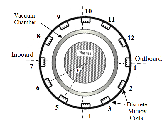 | Figure 1. Position of poloidally array of 12Mirnov coils |
2. Design, Construction, and Experimental Set-up of Hot Limiter Biasing System
In this experiment hot biasing limiter position has been varied between 11.5 and 12.5 cm, and biasing applied between the limiter and the vessel. In fact the hot limiter biasing is an improved limiter biasing that it can be heated with the help of tungsten filament. Hot limiter biasing can emissive electron inside the plasma. The experiments were performed in hydrogen. An average plasma density was in the range 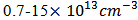 , the toroidal magnetic field induction
  , the plasma current
 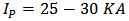 see table 1. The position of poloidally array of 12 Mirnov coils is shown in the Fig. 1. The hot limiter biasing consists of a stainless steel circular head, 2mm in radial direction (width) and 2cm in poloidal direction as shown in the Fig 2.
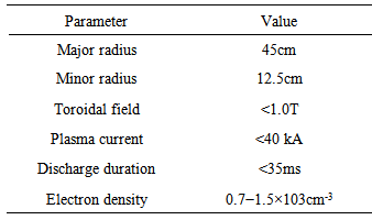
Table 1. Parameters of IR-T1 Tokamak
 |
| |
|
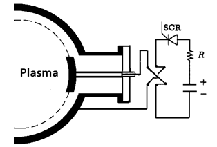 | Figure 2. Schematic drawing of the hot limiter biasing system |
3. Experimental Results and Effects of the Hot Limiter Biasing on the Plasma Modes and Plasma Parameters” in IR-T1 Tokamak
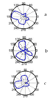
In this section we presented the effects of the hot limiter biasing with positive voltage on the plasma modes, thereafter on fundamental plasma parameters like current plasma, loop voltage, beta poloidal and energy confinement time. As it is known tokamak plasma can support different modes. Cross section of plasma can have different shapes, which are designated as Roset and have M rose leaves. Mirnov coils can record current time series caused by poloidal rotation of plasma. We plotted the polar diagram of the magnetic field fluctuations using FFT analysis on the poloidal array of Mirnov coils (see Fig 3). In these diagrams we showed cross section of plasma at three-time interval in the absence of hot limiter biasing. First time window is during 20-21ms, that shows the mode number is (m=4), second interval is at 24-25ms that mode number is (m=3) and third interval is at 27-28ms that mode number is (m=4).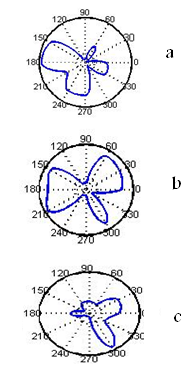 | Figure 3. Cross section of plasma without emissive limiter and RHF. a) Cross section of plasma at time duration at 20.0-21.0ms with mode number m=4; b) Cross section of plasma at time duration at 24.0-25.0ms with mode number m=3; c) Cross section of plasma at time duration at 27.0-28.0ms with mode number m=4 |
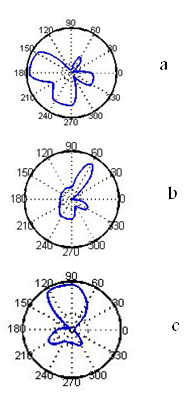
In this contribution we showed cross section of plasma in presence of hot limiter biasing with positive voltage. Fig 4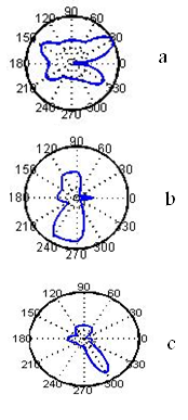 | Figure 4. Cross section of plasma with emissive limiter. a) Cross section of plasma at time duration at 20.0-21.0 ms with mode number m=4; b) Cross section of plasma at time duration at 23.0-24.0ms with mode number m=4; c) Cross section of plasma at time duration at 27.0-28.0ms with mode number m=3 |
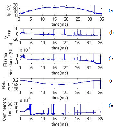
As it is known if the value of M was less than three, plasma will be stable. These diagram show that with inserting hot limiter biasing in edge plasma tokamak we can improve modes number of plasma. In these figs we presented the time evolution of the basic plasma parameters in the absence and presence of hot limiter biasing. In the Figure 5, plasma current, loop voltage, plasma resistance, poloidal beta, and energy confinement time without RHF and hot limiter biasing were shown. Also, in the Fig 6, plasma current, loop voltage, plasma resistance, poloidal beta, and energy confinement time in presence of hot limiter biasing were shown.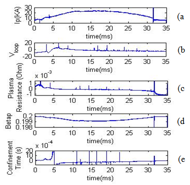 | Figure 5. (a) plasma current, (b) loop voltage, (c) plasma resistance, (d) poloidal beta, (e) energy confinement time without RHF and hot limiter biasing |
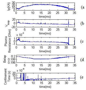
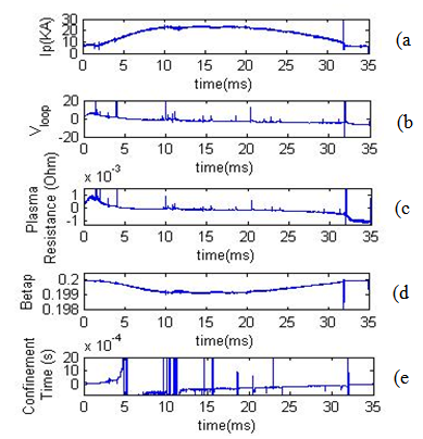 | Figure 6. (a) plasma current, (b) loop voltage, (c) plasma resistance, (d) poloidal beta, (e) energy confinement time in presence of hot limiter biasing |
As we show in these diagrams with inserting emissive limiter biasing energy confinement time increase, because we can observe the plasma current is flatting and there are an increasing in the plasma resistance and plasma temperature. It is known that these results leading to increase of the plasma energy confinement time.
4. Resonant Helical Field Setup on IR-T1 Tokamak and Results of Measurement of Plasma Modes and Plasma Parameters with RHF
The RHF is an external magnetic field which can improve the tokamak plasma confinement. In the IR-T1, this field is produced by two winding with optimized geometry conductors wound externally around the tokamak chamber with a given helicity. The minor radius of these helical windings are 21 cm (L=2, n=1) and 22cm (L=3, n=1) and also major radius is 50 cm (see fig 6). In this experiment, the current through the helical windings was between 200 and 300A, which is very low compared with the plasma current (32KA).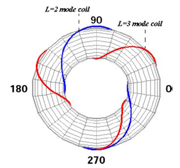 | Figure 7. Positions of the RHF coils (L=2 and L=3modes) on outer surface of the IR-T1 tokamak chamber |
We investigate the effects of RHF on plasma modes in presence of L=2, L=3, and L=2&3 modes, on IR-T1 plasma separately (see Figs 8-10).In these diagrams we investigate the effects of RHF on mode number of plasma. We show that in presence of RHF especially for L=2 and L=2 mode number become less and improvement. In this section we investigate the effects of RHF on plasma parameters, and measure these in presence of L=2, L=3 and L=2&3 modes on IR-T1 plasma (see Fig 11, 12, 13).As we show in presence of RHF the plasma parameters can improvement the properties of plasma confinement time with flatting plasma current and increasing plasma resistance and energy confinement time.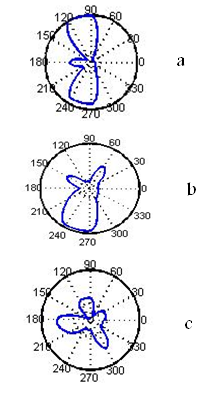 | Figure 8. Cross section of plasma with RHF L=2. a) cross section of plasma at time duration at 20.0-21.0 ms with mode number m=3; b) cross section of plasma at time duration at 23.0-24.0ms with mode number m=3; c) cross section of plasma at time duration at 26.0-27.0ms with mode number m=4 |
 | Figure 9. Cross section of plasma with RHF L=3. a) cross section of plasma at time duration at 19.0-20.0 ms with mode number m=4; b) cross section of plasma at time duration at 23.0-24.0 ms with mode number m=3; c) cross section of plasma at time duration at 26.0-27.0ms with mode number m=3 |
 | Figure 10. Cross section of plasma with RHF L=2&3. a) cross section of plasma at time duration at 20.0-21.0 ms with mode number m=4; b) cross section of plasma at time duration at 23.0-24.0 ms with mode number m=4; c) cross section of plasma at time duration at 26.0-27.0ms with mode number m=3 |
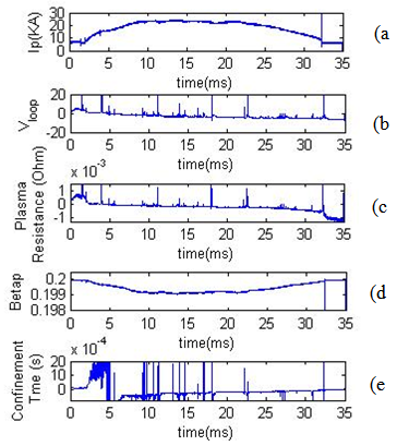
 | Figure 11. (a) plasma current, (b) loop voltage, (c) plasma resistance, (d) poloidal beta, (e) energy confinement time in RHF (L=2) |
 | Figure 12. (a) plasma current, (b) loop voltage, (c) plasma resistance, (d) poloidal beta, (e) energy confinement time in RHF (L=3) |
 | Figure 13. (a) plasma current, (b) loop voltage, (c) plasma resistance, (d) poloidal beta, (e) energy confinement time in RHF (L=2&3) |
5. Summary and Discussion
In this paper we presented the effects of emissive limiter biasing and RHF on the plasma modes and plasma parameters. For this purpose a hot limiter biasing constructed and installed on the IR-T1 tokamak and then the positive voltage applied to limiter inserted inside the tokamak, and modes number of plasma and plasma parameters in the absence and presence of hot limiter biasing were measured. We plotted the polar diagram of the magnetic field fluctuations using FFT analysis on the poloidal array of Mirnov coils. Also we investigate the effects of RHF on the modes number and plasma parameters we measured it, with introducing of different modes of the RHF (L=2, L=3, L=2&3). Results show that hot limiter biasing and RHF with can decrease the plasma fluctuations consequently mode number decrease and plasma parameters improvement.
References
| [1] | I.H. Hutchinson, Principles of Plasma Diagnostics (Cambridge University Press, Cambridge, 1987). |
| [2] | J.P. Freidberg, Ideal MHD (Clarendon, Oxford, 1987). |
| [3] | J. Wesson, Tokamaks (Clarendon, Oxford, 1997). |
| [4] | I.H. Tan, I.L. et al., IEEE Trans. Plasma. Sci. PS-14 3, 279, (1986). |
| [5] | K. Harafuji, T. Hayashi, T. Sato, Plasma Phys. Contr. F. 29, 1183-1499 (1987). |
| [6] | E.J. Strait et al., Fusion Sci. Technol. 53, 304-330, pp.105-131. |
| [7] | V.S. Mukhovatov, V.D. Shafranov, Nucl. Fusion 11, 605 (1971). |
| [8] | S.H Seo, Phys. Plasmas 16, 032501 (2009). |
| [9] | M. Emami, M. Ghoranneviss, A. SalarElahi, A. Rahimi Rad, J. Plasma Phys. Published 30 April (2009). |
| [10] | A. SalarElahi et al., J. Fusion Energ. (2009). Doi:10.1007/s 10894-009-9198-x. |
| [11] | A. Hojabri et al., 32nd EPS, (Tarragona, Spain, 2005) ECA 29C, P4.064. |
| [12] | L. Guazzotto, R. Betti, Phys. Plasmas 12, 056107 (2005). |
| [13] | J.P Freidberg, F.A. Haas, Phys. Fluids 16,1909 (1973). |
| [14] | E.J Strait et al., Fusion Sci. Technol. 53, 304-330 (2006). |
| [15] | M. Shimada, D.J. Campell, V. Mukhovatov et al., Nucl. Fusion 47, S1 (2007). |
| [16] | G. Van Oost et al., Plasma Phys. Control Fusion 45,621 (2003). |
| [17] | I.C. Nascimentto et al., Nucl. Fusion 45,796-803 (2005). |
| [18] | C. Silva et al. 17th IAEA fusion energy conference, EX/P1-10, Lyon, Oct 2002. |
 Abstract
 Reference
 Full-Text PDF
 Full-text HTML