| [1] | V. S. Mukhovatov and V. D. Shafranov: Nucl. Fusion 11, (1971), 605. |
| [2] | J. Wesson, Tokamaks, Clarendon, Oxford, 1997, pp. 105–131. |
| [3] | E. J. Strait and et al., 2006, Fusion Science and Technology, 53, pp. 304-330. |
| [4] | M. Spolaore et al., Czech. J. Phys. 55 (12), 1615-1621, (2005). |
| [5] | P. Devynck et al., Physics of Plasmas 13 (10), 102505-102513, (2006). |
| [6] | A. Salar Elahi et al., IEEE Trans. Plasma Science, 40, 892-897, (2012). |
| [7] | B. Viatcheslav et al., J. Plasma Fusion Res. 5, 418-423, (2002). |
| [8] | E. Y. Wang et al., Nucl. Fusion 35, 467, (1995). |
| [9] | Ch. P. Ritz et al., Rev. Sci. Instrum. 59, 1739-1744, (1998). |
| [10] | V. V. Bulanin et al., Plasma Phys. Control. Fusion 48, A101, (2006). |
| [11] | J. A. C. Cabral et al., Plasma Phys. Control. Fusion 40, 1001, (1998). |
| [12] | C. Silva et al., 17th IAEA Fusion Energy Conference, EX/P1-10 Lyon, France, (2002) |
| [13] | A. Salar Elahi et al., IEEE Trans. Plasma Science 38 (2), 181-185, (2010). |
| [14] | A. Salar Elahi et al., IEEE Trans. Plasma Science 38 (9), 3163-3167, (2010). |
| [15] | M. Emami, M. Ghoranneviss, A. Salar Elahi and A. Rahimi Rad, J. Plasma Phys. 76 (1), 1-8, (2009). |
| [16] | A. Salar Elahi et al., Fusion Engineering and Design 85, 724–727, (2010). |
| [17] | A. Salar Elahi et al., Phys. Scripta 80, 045501, (2009). |
| [18] | A. Salar Elahi et al., Phys. Scripta 80, 055502, (2009). |
| [19] | A. Salar Elahi et al., Phys. Scripta 81 (5), 055501, (2010). |
| [20] | A. Salar Elahi et al., Phys. Scripta 82, 025502, (2010). |
| [21] | M. Ghoranneviss, A. Salar Elahi et al., Phys. Scripta 82 (3), 035502, (2010). |
| [22] | A. Salar Elahi et al., J. Fusion Energy 28 (4), 346-349, (2009). |
| [23] | A. Salar Elahi et al., J. Fusion Energy 28 (4), 416-419, (2009). |
| [24] | A. Salar Elahi et al., J. Fusion Energy 28 (4), 408-411, (2009). |
| [25] | A. Salar Elahi et al., J. Fusion Energy 28 (4), 412-415, (2009). |
| [26] | A. Salar Elahi et al., J. Fusion Energy 28 (4), 394-397, (2009). |
| [27] | A. Salar Elahi et al., J. Fusion Energy 28 (4), 404-407, (2009). |
| [28] | A. Salar Elahi et al., J. Fusion Energy 28 (4), 390-393, (2009). |
| [29] | A. Salar Elahi et al., J. Fusion Energy 28 (4), 385-389, (2009). |
| [30] | A. Rahimi Rad, M. Ghoranneviss, M. Emami, and A. Salar Elahi, J. Fusion Energy 28 (4), 420-426, (2009). |
| [31] | A. Salar Elahi et al., J. Fusion Energy 29 (1), 1-4, (2010). |
| [32] | A. Salar Elahi et al., J. Fusion Energy 29 (1), 22-25, (2010). |
| [33] | A. Salar Elahi et al., J. Fusion Energy 29 (1), 29-31, (2010). |
| [34] | A. Salar Elahi et al., J. Fusion Energy 29 (1), 26-28, (2010). |
| [35] | A. Salar Elahi et al., J. Fusion Energy 29 (1), 32-35, (2010). |
| [36] | A. Salar Elahi et al., J. Fusion Energy 29 (1), 36-40, (2010). |
| [37] | A. Salar Elahi et al., J. Fusion Energy 29 (1), 62-64, (2010). |
| [38] | A. Salar Elahi et al., J. Fusion Energy 29 (1), 76-82, (2010). |
| [39] | A. Rahimi Rad, M. Emami, M. Ghoranneviss, A. Salar Elahi, J. Fusion Energy 29 (1), 73-75, (2010). |
| [40] | A. Salar Elahi et al., J. Fusion Energy 29 (1), 83-87, (2010). |
| [41] | A. Salar Elahi et al., J. Fusion Energy 29 (1), 88-93, (2010). |
| [42] | A. Salar Elahi et al., J. Fusion Energy 29 (3), 209-214, (2010). |
| [43] | A. Salar Elahi et al., J. Fusion Energy 29 (3), 232-236, (2010). |
| [44] | A. Salar Elahi et al., J. Fusion Energy 29 (3), 251-255, (2010). |
| [45] | A. Salar Elahi et al., J. Fusion Energy 29 (3), 279-284, (2010). |
| [46] | M. Ghoranneviss, A. Salar Elahi et al., J. Fusion Energy 29 (5), 467-470, (2010). |
| [47] | A. Salar Elahi et al., J. Fusion Energy 29 (5), 461-465, (2010). |
| [48] | A. Salar Elahi et al., Brazilian J. Physics 40 (3), 323-326, (2010). |
| [49] | A. Salar Elahi et al., J. Fusion Energy 30 (2), 116-120, (2011). |
| [50] | M.R. Ghanbari, M. Ghoranneviss, A. Salar Elahi et al., Phys. Scripta 83, 055501, (2011). |
| [51] | A. Salar Elahi, J. Fusion Energy 30 (6), 477-480, 477-480, (2011). |
| [52] | A. Salar Elahi et al., Fusion Engineering and Design 86, 442–445, (2011). |
| [53] | A. Salar Elahi et al., J. Fusion Energy 31 (2), 191-194, (2012). |
| [54] | M.R. Ghanbari, M. Ghoranneviss, A. Salar Elahi and S. Mohammadi, Radiation Effects & Defects in Solids 166 (10), 789–794, (2011). |
| [55] | A. Salar Elahi et al., IEEE Trans. Plasma Science (January 2013, in press), DOI: 10.1109/TPS.2012.2235186. |
| [56] | A. Salar Elahi et al., Accepted for publication in Radiation Effects & Defects in Solids (January 2012, in press), DOI: 10.1080/10420150.2011.650171. |
| [57] | Z. Goodarzi, M. Ghoranneviss and A. Salar Elahi, Accepted for the publication in J. Fusion Energy (March 2012, in press), DOI: 10.1007/s10894-012-9526-4. |
| [58] | M.R. Ghanbari, M. Ghoranneviss, A. Salar Elahi et al., Phys. Scripta 85 (5), 055502, (2012). |
| [59] | A. Salar Elahi et al., Accepted for the publication in Radiation Effects and Defects in Solids (June 2012, in press), DOI: 10.1080/10420150.2012.706609. |
| [60] | A. Salar Elahi et al., Accepted for the publication in Radiation Effects and Defects in Solids (June 2012, in press), DOI: 10.1080/10420150.2012.706607. |
| [61] | K. Mikaili Agah, M. Ghoranneviss, A. Salar Elahi et al., accepted for the publication in J. Fusion Energy (July 2012, in press), DOI: 10.1007/s10894-012-9563-z. |
| [62] | A. Salar Elahi et al., J. Nuclear and Particle Physics 1(1), (2011), 10-15, DOI: 10.5923/j.jnpp.20110101.03. |
| [63] | A. Salar Elahi et al., J. Nuclear and Particle Physics 2(2), (2012), 1-5, DOI: 10.5923/j.jnpp.20120202.01. |
| [64] | A. Salar Elahi et al., Fusion Engineering and Design (January 2013, in press), DOI: 10.1016/j.fusengdes. 2012.12.001. |
| [65] | A. Salar Elahi et al., J. Nuclear and Particle Physics 2(2), 22-25, (2012), DOI: DOI: 10.5923/j.jnpp.20120202.05. |
| [66] | A. Salar Elahi et al., J. Nuclear and Particle Physics 2(5), 112-118, (2012), DOI: 10.5923/j.jnpp.20120205.02. |
| [67] | A. Salar Elahi et al., J. Nuclear and Particle Physics 2(6), 142-146, (2012), DOI: 10.5923/j.jnpp.20120206.02. |
 Abstract
 Reference
 Full-Text PDF
 Full-text HTML
 ). Therefore, the plasma internal inductance is can be obtained using subtraction. Also the value of
  is determined by the radial distribution of toroidal current profile of the plasma [1-13]. In this paper we presented an experimental approach based on the diamagnetic loop and magnetic probe, and moreover an approximate calculations for determination of the plasma internal inductance in IR-T1 Tokamak, which is a small, low
  and large aspect ratio tokamak with a circular cross section (see Table 1) [14-67]. Details of the experimental approach for measurement of the plasma internal inductance will be presented in section 2. Details of approximate calculations for determination of the internal inductance will be presented in section 3. Experimental results will be discussed in section 4. Also summary will be presented in section 5.
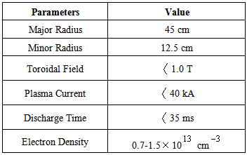
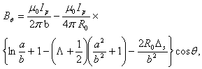
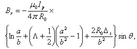
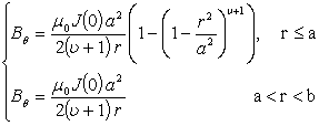
 is the major radius of the vacuum vessel,
  is the Shafranov shift,
  is the plasma current,
  and
and  are the minor plasma radius and minor chamber radius respectively, and
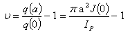
  is the Shafranov parameter. These equations accurate for low
  plasma and circular cross section tokamaks as IR-T1, and where:
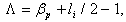
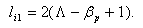
 is the poloidal beta, and
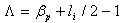
  is the plasma internal inductance. Rearranging of the Eq. (3) give us the first relation for
  :
:
 , where n is the number of turns of coil, A is the average area of cross section of coil, and B is the local magnetic field parallel to the coil axis.The induced voltage in the magnetic probe and then magnetic field is:
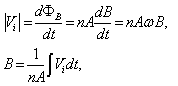
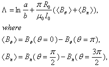
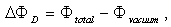
 is the frequency of the fluctuations of the magnetic field. Therefore in order to measurement of the magnetic field distribution we must be integrating the output signals of the magnetic probe.On the other hand, diamagnetic loop measures the toroidal diamagnetic flux for the purpose of measurement of the poloidal beta and thermal energy of the plasma. It is usually a single wire which circling the plasma column either inside or outside of the plasma vacuum chamber. Intrinsically this loop will also pickup the toroidal magnetic flux from the toroidal field coil and any current circulating in the poloidal plane, in particular toroidal field coil current, eddy currents in the conducting vacuum chamber induced during transient changes in the plasma energy and plasma current. In other words, the diamagnetic loop consist of a simple loop that links the plasma column, ideally located in a poloidal direction in order to minimize detecting the poloidal field. Relation between the diamagnetic flux and the poloidal beta derived from simplified equilibrium relation [2-4] is:
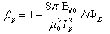
 and where
 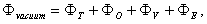 where
where  is the toroidal magnetic field in the absence of the plasma which can be obtained by the magnetic probe or diamagnetic loop,
  is the plasma current which can be obtained by the rogowski coil,
  is the toroidal flux because of toroidal field coils,
  and
and  are the passing flux through loop due to possible misalignment between ohmic field and vertical field and the diamagnetic loop and
  is the toroidal field due to eddy current on the vacuum chamber. These fluxes can be compensated either with compensation coil or dry runs technique. It must be noted that compensating coil for diamagnetic loop is wrapped out of the plasma current, and only the toroidal flux (which is induced by the change of toroidal field coil current when plasma discharges) can be received. According to above discussion, we designed, constructed, and installed four magnetic probes and also diamagnetic loop with its compensation coil, on outer surface of the IR-T1, in order to measurements of the Shafranov parameter and poloidal beta, respectively. Plasma current is also measured with Rogowski coil. Experimental results will be presented in the section 4.
 can be determined from the conservation of zeroth order magnetic energy:
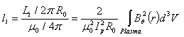
 (usually accurate for low beta tokamak), as:
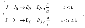
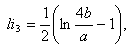
 .Then first approximate value for the internal inductance can be easily obtained by substituting Eq. (9) in Eq. (8):
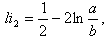
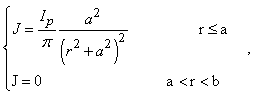
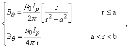
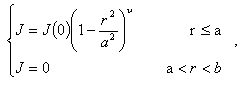
 , then the fourth approximate values of the internal inductances can be determined from substituting the Eq. (15) in Eq. (8) as a function of the
  . Results present in table 2 and Figure (1).
 for IR-T1 tokamak parameters
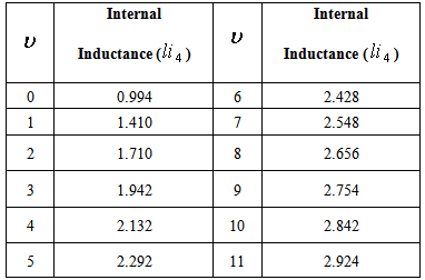
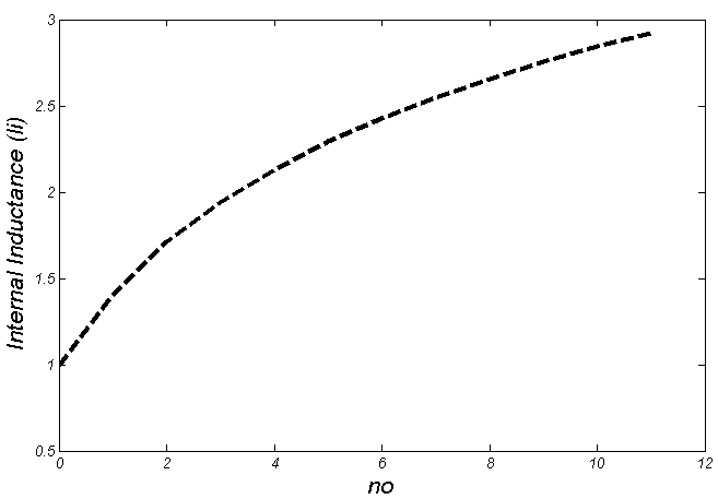
 for IR-T1 tokamak parameters
 which proportional to the edge safety factor reduced from 8 to 1 along time interval of plasma current (see Figure (2)). Therefore, according to recent calculations for the IR-T1 tokamak plasma, the values of internal inductance reduced from 2.5 to 1.2 along the time interval of plasma current.
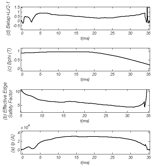
 of the radius
  in angles of
  and
and  to detect the tangential component of the magnetic field
  and two magnetic probes are also installed above,
  , and below,
  , to detect the normal component of the magnetic field
  .Also, a diamagnetic loop with its compensation coil were constructed, and installed on outer surface of the IR-T1 tokamak chamber, and then the poloidal beta measured from them. After measurements of
  and
and  , and then the Shafranov parameter from magnetic probes,
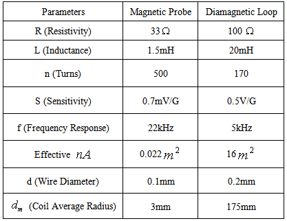
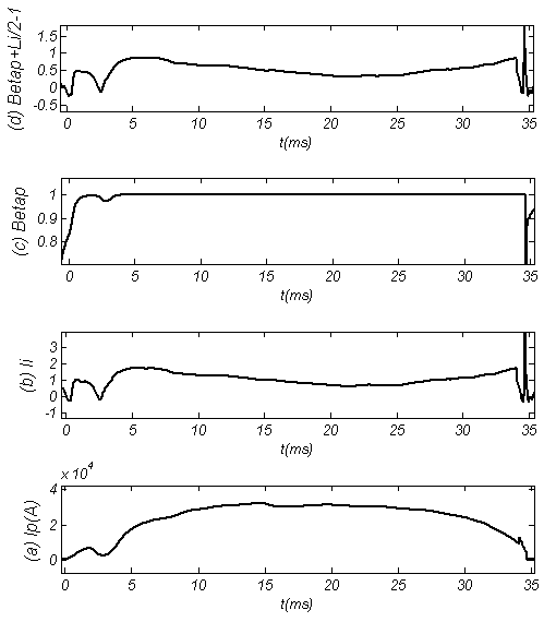
  from rogowski coil, poloidal beta from diamagnetic loop and substituting them in to Eq. (4), the internal inductance was measured. Results presented in the Fig. (3). Design parameters of the magnetic pickup coils presented in Table 3. Diamagnetic loop and its compensating coil also were constructed and installed on the IR-T1 tokamak. Its characteristics are also shown in Table 3.