A. Salar Elahi, M. Ghoranneviss
Plasma Physics Research Center, Tehran Science and Research Branch, Islamic Azad University, Tehran, Iran
Correspondence to: A. Salar Elahi, Plasma Physics Research Center, Tehran Science and Research Branch, Islamic Azad University, Tehran, Iran.
| Email: |  |
Copyright © 2012 Scientific & Academic Publishing. All Rights Reserved.
Abstract
We presented a simple diagnostic technique for determination of plasma displacement based on poloidal flux loops in IR-T1 tokamak. This instrument consists of a two semicircle loops which installed toroidally on inner and outer sides of tokamak chamber and connected with each other. In other words, this instrument detects the difference of poloidal fluxes on high field side and low field side, which we needed in calculating of the Shafranov shift. Main benefits of our proposed instrument are its simplicity, and also its output is directly relate to the plasma column displacement. Based on this technique we determined the plasma position, and result compared with magnetic probes method. Results are in good agreement with each other.
Keywords:
Tokamak, Plasma Displacement, Poloidal Flux
Cite this paper: A. Salar Elahi, M. Ghoranneviss, A Simplified Technique Based on Flux Loops for Determination of Tokamak Plasma Horizontal Displacement, Journal of Nuclear and Particle Physics, Vol. 4 No. 2, 2014, pp. 65-68. doi: 10.5923/j.jnpp.20140402.03.
1. Introduction
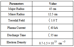
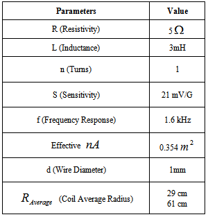
Plasma position measurement is very important in control of tokamak operation, especially in control of plasma equilibrium, density, and confinement time. Therefore it is a significant fraction of the tokamak plasma studies and experiments in order to achieve optimized operation and become close to Lawson criterion. Heretofore, different methods for determination of plasma equilibrium state (in equilibrium state the plasma pressure is balanced by electromagnetic force) based on magnetic measurements have been proposed and studied on the tokamaks [1-23]. Commonly, in circular cross section tokamaks magnetic probes and in elongated tokamaks flux loops methods have been used. In this paper we presented a simple magnetic diagnostic based on poloidal magnetic flux for determination of plasma position in IR-T1 Tokamak, which it is a small, low β and large aspect ratio tokamak with a circular cross section (see table 1). Main benefits of our proposed instrument are its simplicity and also direct relation between its output and the plasma column displacement. Details of the theoretical approach for this technique will be discussed in section 2. Design and construction of this diagnostic will be presented in section 3. Details of the experimental results and comparing of them will be presented in section 4. Summary will be presented in section 5.Table (1). Main parameters of the IR-T1 tokamak
 |
| |
|
2. Determination of Plasma Position Based on the Flux Loop
Our proposed instrument consists of a two semicircle loops with two different radiuses which connected with each other. In other words, this instrument play a role of two poloidal flux loop (poloidal flux loop is a simple toroidally loop which measure the poloidal magnetic flux and usually array of them use in control and reconstruction of plasma equilibrium states) which located at inner and outer side of vacuum chamber, but its output is the differences of poloidal flux at HFS and LFS. The magnetic flux passing through such a loop is equal to  , where
  represent to magnetic poloidal flux. In the ohmically heated tokamaks, ohmic coils field is the main fraction of poloidal flux which passing through the flux loop. Therefore to obtain net poloidal flux due to plasma, compensation will require for all excessive flux. Because of large area of the flux loop, the inductive voltage is also large and then it consists of usually one turn. According to relation for frequency response
 , it is obvious that because of small self inductance, frequency response of flux loop usually is higher than which desired. Although magnetic probe suitable for measurement of plasma position only in circular cross section plasma and not for elongated one, but the our proposed instrument either in elongated and or circular cross section tokamaks can be used, such as the flux loops. Therefore, in order to comparing our results we used these two techniques for the circular cross section tokamak such as IR-T1. The plasma boundary is usually defined by LCFS. In the LCFS poloidal magnetic flux is constant and if we install our instrument in vicinity of LCFS, then we can find plasma displacement according to Shafranov equation from difference in poloidal fluxes that detected by such instrument. In the quasi-cylindrical coordinates
  for the equilibrium magnetic flux we have [1]:
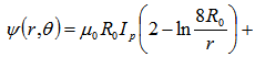
 where
where  | (1) |
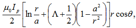
and where  are the plasma current, major and minor plasma radiuses, poloidal beta and internal inductance of the plasma. The Shafranov shift can be deduced by finding the maximum of flux function on midplane:
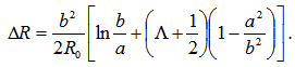 | (2) |
By rearranging the Eq. (1) we have: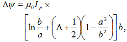 | (3) |
where  | (4) |
Therefore by combination of Equations (2) and (3) the relationship between equilibrium magnetic flux and plasma displacement obtained: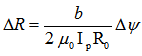 | (5) |
Common way for measurement of poloidal flux is the poloidal flux loop. Usually in elongated tokamaks an array of flux loops uses for measurements of poloidal flux at different angles and then compensation, subtraction, and determination of plasma column displacement.Main benefits of this instrument are its simplicity, and also its output is directly proportional to plasma column displacement (see Fig. (1)).
3. Design and Construction of this Diagnostic for the Determination of Plasma Position
As shown in Figure (1), the difference of poloidal fluxes which detect by the instrument is: | (6) |
Table (2). Design parameters of the instrument
 |
| |
|
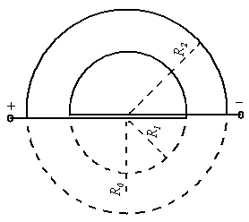 | Figure (1). Schematic representation of the new instrument where installed on outer surface of the IR-T1 tokamak |
In the IR-T1 tokamak this instrument designed and installed on outer surface of the vacuum chamber in polar coordinates  with radiuses
  and
and  (see Figure (1) and Table (2)). Therefore the first relation for Shafranov shift is:
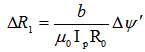 | (7) |
It is must be noted that the ohmic field is the significant fraction of the poloidal flux which passing through the instrument, therefore essentially compensation is needed. Compensation is done with all fields discharge without plasma and subtraction them from the total flux that received with instrument. Experimental result for the measurement of plasma position using this technique presented in the next section.
4. Experimental Results and Comparison between Them
The electric circuit that used for the measurement of induced voltage  in the instrument showed in Figure (2):
 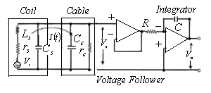 | Figure (2). Electric circuit used for novel instrument and magnetic probe methods |
In the diagram,  is the current in the coil circuit and
  is the coaxial cable output signal. The application of Kirchhoff’s voltage law for this circuit yields the following equation:
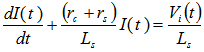 | (8) |
where  and
and  are the loop resistivity and cable resistivity respectively, and
  is the loop self-inductance. From the circuit of Figure (2) we have:
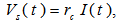 | (9) |
Therefore, for steady state current from Eq. (16) we have: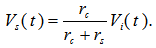 | (10) |
So, the integrator output  of Figure (2) is given by:
 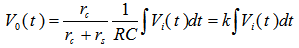 | (11) |
where RC is the integrator time constant and  is the inductive voltage supplied by instrument.According to Eq. (11) and for induced voltage in the instrument, we can write:
 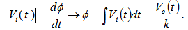 | (12) |
where k is the constant which depends on cable, coils, and new instrument resistances and time constant of integrator. As shown in Figure (3), comparison of this technique with magnetic probe result show that two techniques are in good agreement with each other. 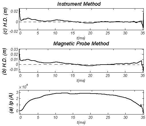 | Figure (3). Horizontal Displacement (H.D.) obtained by (c) new instrument and (b) Magnetic probe methods, along the (a) plasma current |
5. Summary
We presented the simple diagnostic for the determination of plasma displacement in the IR-T1 tokamak. This instrument consists of a two semicircle loops which installed toroidally on inner and outer sides of tokamak chamber and connected with each other. Really, this instrument receives the difference of poloidal flux on high field side and low field side of a tokamak chamber, which we needed in calculating of the plasma column displacement. Main benefits of our proposed instrument are its simplicity and its direct relation to the plasma displacement. Based on this technique we determined plasma position in IR-T1 and results compared with magnetic probe method. Results are in good agreement with each other.
References
| [1] | V. S. Mukhovatov and V. D. Shafranov, Nucl. Fusion 11, 605, (1971). |
| [2] | Hiromasa Niomiya and Norio Suzuki, Japanese Journal of Applied Physics, Vol. 21, No.9, September, pp. 1323-1327, (1982). |
| [3] | J. Wesson, Tokamaks, Clarendon, Oxford, pp. 105–131, (1997). |
| [4] | I. H. Hutchinson, Principles of Plasma Diagnostics, Cambridge University Press, Cambridge, pp. 10–33, (1987). |
| [5] | E. J. Strait and et.al., Magnetic Diagnostics, Fusion Science and Technology, Vol. 53, pp. 304-330, (2006). |
| [6] | S. H. Seo, Phys. Plasmas 16, 032501 (2009). |
| [7] | J. Chung and D. C. Seo, Rev. Sci. Instrum. 79, 083504 (2008). |
| [8] | A. J. Wootton, Nucl. Fusion 19, 987 (1979). |
| [9] | P. J. Mc Carthy, Phys. Plasmas 6, number 9 (1999). |
| [10] | M, Shimada, D. J. Campbell, V. Mukhovatov et al., Nucl. Fusion 47, S1 (2007). |
| [11] | Salar Elahi A. et al., 2009, J Fusion Energy, DOI 10.1007/s10894-009-9198-x. |
| [12] | Salar Elahi A. et al., 2009, J Fusion Energy, DOI 10.1007/s10894-009-9218-x. |
| [13] | Salar Elahi A. et al., 2009, J Fusion Energy, DOI 10.1007/s10894-009-9216-z. |
| [14] | Salar Elahi A. et al., 2009, J Fusion Energy, DOI 10.1007/s10894-009-9207-0. |
| [15] | Salar Elahi A. et al., 2009, J Fusion Energy, DOI 10.1007/s10894-009-9208-z. |
| [16] | Salar Elahi A. et al., 2009, J Fusion Energy, DOI 10.1007/s10894-009-9212-3. |
| [17] | Salar Elahi A. et al., 2009, J Fusion Energy, DOI 10.1007/s10894-009-9210-5. |
| [18] | Salar Elahi A. et al., 2009, J Fusion Energy, DOI 10.1007/s10894-009-9214-1. |
| [19] | Salar Elahi A. et al., 2009, J Fusion Energy, DOI 10.1007/s10894-009-9213-2. |
| [20] | Salar Elahi A. et al., 2009, J Fusion Energy, DOI 10.1007/s10894-009-9215-0. |
| [21] | A. Salar Elahi et al., Phys. Scripta 80, 045501 (2009). |
| [22] | A. Salar Elahi et al., Phys. Scripta 80, 055502 (2009). |
| [23] | A. Salar Elahi et al., IEEE T. on Plasma Science 38 (2), (2010). |
 Abstract
 Reference
 Full-Text PDF
 Full-text HTML