A. Salar Elahi, M. Ghoranneviss
Plasma Physics Research Center, Tehran Science and Research Branch, Islamic Azad University, Tehran, Iran
Correspondence to: A. Salar Elahi, Plasma Physics Research Center, Tehran Science and Research Branch, Islamic Azad University, Tehran, Iran.
| Email: |  |
Copyright © 2012 Scientific & Academic Publishing. All Rights Reserved.
Abstract
In this research we presented a current independent measurement of plasma displacement in IR-T1 tokamak. The main advantage of this technique is that it based only on the magnetic probes measurement. Based on this technique, four magnetic pickup coils with frequency response of 22 kHz and sensitivity of 0.7mV/G were designed, constructed and installed on outer surface of the IR-T1 tokamak chamber and then plasma displacement measured from them. The magnetic probes were calibrated using a simple and reliable calibration technique and the calibration factor is found to be 0.14 ± 0.01 T/V. Also the result of plasma displacement measurement was compared with analytical one and found in good agreement with each other.
Keywords:
Tokamak, Plasma Displacement, Magnetic Probes
Cite this paper: A. Salar Elahi, M. Ghoranneviss, Discrete Coils Based Measurement of Plasma Displacement in the IR-T1 Tokamak, Journal of Nuclear and Particle Physics, Vol. 4 No. 1, 2014, pp. 42-46. doi: 10.5923/j.jnpp.20140401.07.
1. Introduction
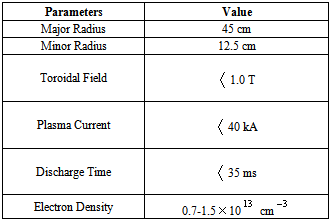
The tokamak configuration is the most promising candidate for a viable commercial fusion reactor. Before this very promising energy source can be harnessed, many scientific and technological problems must first be resolved. One of the principal problems facing magnetic confinement schemes such as the tokamak configuration is the issue of stably maintaining the plasma column within the discharge chamber. In order to accomplish this, a suitably shaped magnetic field structure must be produced.The tokamak plasma is subjected to several forces in the major radial direction that must be dynamically counterbalanced by an appropriate magnetic Lorentz force in order to maintain plasma equilibrium in the horizontal direction. In general, in the low beta tokamaks, radial pressure balance is achieved by the poloidal field, and also toroidal force balance is achieved by interaction of the external vertical field with toroidal current (when inward Lorentz force equal with sum of the three outward forces (hoop force, tire tube force, and 1/R force) due to the toroidal configuration of the tokamak). But, in toroidal force balance problem, the two opposite forces may not be equal, and therefore plasma intend to shift inward or outward, which is a very dangerous for tokamak plasma equilibrium. Therefore, plasma equilibrium study is one of the fundamental problems of the magnetically confined plasmas. In other words, control of plasma position has important role in plasma confinement and to achieve optimized tokamak plasma operation. Determination of accurate plasma position during confinement time is essential to transport it to a control system based on feedback. There are many available global solutions of the steady state magnetohydrodynamics equations, in particular, the Grad-Shafranov equation. Over the years different techniques have been developed to determine the plasma displacement from the canter of vacuum chamber in tokamaks[1-19].Table 1. The range of plasma parameters of the IR-T1 Tokamak
 |
| |
|
In this contribution we presented a current independent measurement (only based on the magnetic probes measurements) of plasma displacement in IR-T1 tokamak, which is a small, air core, low  and large aspect ratio tokamak with a circular cross section, (see Table 1). This technique based on magnetic probes measurement, for determination of plasma displacement will be discussed in section 2. Description of the used diagnostic will be discussed in section 3. In order to compare of the result, analytical method is also experimented, experimental results and comparison between them will be presented in section 4. Summary and conclusion are also will be discussed in section 5.
2. Magnetic Probes Based Measurement of Plasma Displacement
Because of dependence of the plasma position and plasma current distribution to magnetic field distributions around the plasma, therefore magnetic pickup coils give us information about the plasma position or Shafranov shift,  . Poloidal and normal magnetic fields distributions around the plasma are[1,2]:
 | (1) |
 | (2) |
where  ,
,  ,
,  ,
,  , and
, and  are the plasma radius, chamber minor and major radiuses, free space permeability, and plasma current, respectively, and where:
 | (3) |
Therefore, by rearranging the above equations, a current independent relation for the plasma displacement obtained: | (4) |
where we used the quasi-cylindrical coordinates ( ). Equations (1) and (2) accurate for the low
  , large aspect ratio and circular cross section tokamaks as IR-T1.
3. Description of the Used Diagnostic
The only used diagnostic to measure the plasma displacement in the IR-T1 tokamak was array of magnetic probes. The following paragraphs provide information about the principle and design consideration of the magnetic probes and a description of the IR-T1 tokamak. Basically a magnetic probe is an inductive coil made by winding a thin gauge of wire on to a small nonmagnetic bobbin. It works on the principle of Faraday’s laws of electromagnetic induction. The induced electromotive force ( ) produced in such a coil due to change in the magnetic flux (
 ) is given by
 | (5) |
For a coil of  turns and a cross-sectional area
  small enough such that the magnetic field does not vary over it then equation (5) becomes
 | (6) |
where  is the component of magnetic field which parallel to the axis of the coil. Since from equation (6) it is clear that the coil delivers a voltage signal (
 ) proportional to
  , to display
  one needs to integrate the signal before its presentation for recording. Integration of the signal can be done either by interposing a simple RC passive integrator between the probes and the data acquisition or by using computational software. The equivalent circuit of the magnetic probe along with the RC integrator is shown in Fig. (1).
 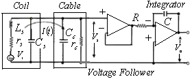 | Figure (1). Block diagram of the circuit used for the magnetic probes |
The circuit equation (neglecting the coil resistance) is expressed as | (7) |
where  is the current flowing through the circuit,
  is the inductance of the coil,
  is the resistance of the integrating network and
  is the capacitance of the integrating network. If the reactance of the inductance
  (where
  is the angular frequency of the magnetic field) is much less than the resistance
  and the integrating time constant
  is much greater than the total observation time (
 ) of the signal, then one can write from equation (7)
 | (8) |
Thus the output voltage  is given by
 | (9) |
Due to the interrelation of various characteristics of the magnetic probes it is not possible to improve its features in one respect without affecting its performance in other ways, as explained below. Main design parameters of the magnetic pickup coils are its frequency response and sensitivity. We selected the frequency response of the magnetic probes, 22 kHz. Thus first relation for designing the magnetic probes is the frequency response; the second relation is the sensitivity of the magnetic probe, and third relation is the ohm law. The coil resistance, coil inductance, winding turns of coil, length of coil, and coil radius, are the five interrelated desired parameters. Because of parameters multiplicity and relation limitation, these parameters must be obtained from the three basic relations mentioned above. The first basic relation which mentioned is the frequency response of coil: | (10) |
where  is a constant which depending on the ratio of the coil length
  to its radius
  (for
(for  ). The second relation is the sensitivity of the magnetic probes:
 | (11) |
The third relation is the famous ohm law: | (12) |
where  and
and  are the length of total wire which used, and cross section area of the used wire. Therefore we introduced the values of two desired sensitivity and frequency response, and then other parameters obtained from above three relations. In our case the values of
  ,
,  ,
,  and
and  were 0.022
  , 1.5mH, 22kHz and 0.7mV/G respectively.It is necessary to devise an accurate and reliable calibration technique for the absolute quantitative measurements of magnetic field using magnetic probes. For this, the foremost requirement is that an accurately known calibrating pulsed field be available and its pulsed period should be nearer to that of the experimental apparatus. Apart from the pulsed period, the calibrating field should be homogeneous in a sufficiently large region such that the presence of the probe inside the calibrating field should not affect it. In addition, the field strength of the calibrating field must be sufficient to provide an accurately measurable signal from the magnetic probe[20-21]. The magnetic probes were calibrated using a simple, novel and reliable calibration technique. The above-mentioned criteria of a homogeneous magnetic field can be realized only with the help of a Helmholtz coil. A Helmholtz coil principally consists of two similar coils each having the same radius (
 ) and number of turns (
 ). The coils are placed at a distance (
 ) apart and a current (
 ) flows through them in the same direction. The magnitude of magnetic field at the midpoint between the two coils can be accurately calculated from the current using the formula:
 | (13) |
A Helmholtz coil with 50 turns was constructed by winding enameled copper wire on a Teflon tube of diameter 10 cm. A hole of diameter 5mm was drilled at the center of the two coils on the tube perpendicular to the axis of the coil, which allows accurate positioning of the magnetic probes relative to the magnetic field. Inserting the magnetic probe into the hole, a capacitor was discharged through the Helmholtz coil so that a pulsed field of similar time period to that of the experimental device (30ms) was produced in the Helmholtz coil. The discharge current ( , where
  is the capacitance,
  is the charging voltage of the capacitor and
  is the inductance of the Helmholtz coil) in the Helmholtz coil was monitored with the help of a Rogowski coil to estimate the magnetic field using equation (13). The signals from the magnetic probe and Rogowski coil were simultaneously compared to calculate the calibration factor. The estimated calibration factor for the magnetic probes in our case was 0.14 ± 0.01 T/V.Based on the mentioned technique in section 2, in the IR-T1 tokamak four magnetic probes were designed, constructed, and installed. Two magnetic probes were located on the circular contour
  of the radius
  in angles of
  and
and  to detect the tangential component of the magnetic field
  and two magnetic probes are also located above,
  , and below,
  , to detect the normal component of the magnetic field
  , as shown in the Fig. (2). The magnetic fields measured by the magnetic probes consists of the desired magnetic fields produced by the plasma current as well as unwanted magnetic fields such as that produced by the toroidal field coils. This happens primarily as a result of misalignments of the probes. In order to eliminate, or at least to reduce, these stray magnetic fields, the waveforms to which they correspond are added with suitable polarity to the measured signals via an adjustable gain passive mixer. To accomplish this, the gains are adjusted in the absence of the plasma, while all other fields are present, until the coil signals are zero or as close to zero as possible. After compensation and integration of magnetic probes output, and by substituting the poloidal and normal components of the magnetic fields in Equation (4), displacement of the plasma column center was determined. Experimental results presented in the next section.
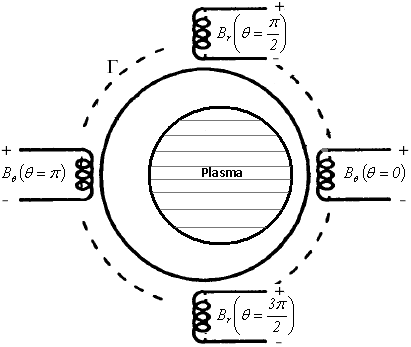 | Figure (2). Positions of the four magnetic probes on outer surface of the IR-T1 tokamak chamber |
4. Experimental Result and Comparison with an Analytical Technique
The result of this technique and comparison with analytical technique are presented in the Fig. (3). These figures show that results of two methods are in good agreement with each other. Moreover we plotted the magnetic flux surfaces for plasma parameters at t=10ms in target shot on IR-T1 tokamak, as observable in Fig. (4), there is 5mm inward displacement of plasma column center from the chamber center.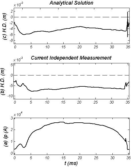 | Figure (3). Time evolution of the (a) Plasma current, (b) Horizontal Displacement (H.D.) measured by the current independent technique, and (c) H.D. obtained by the analytical method along the plasma current |
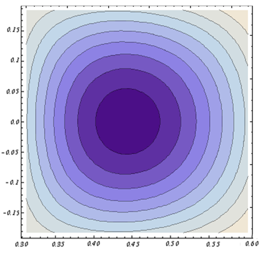 | Figure (4). Magnetic flux surfaces at t=10ms in target shot on IR-T1 Tokamak, where 5mm inward displacement of the plasma column center clearly observable |
5. Summary and Conclusions
In this contribution we presented a current independent measurement of plasma displacement in IR-T1 tokamak. The main advantage of this technique is that it based only on the magnetic probes measurement (in this technique plasma current measurement is not need). Based on this method, four magnetic pickup coils with frequency response of 22 kHz and sensitivity of 0.7mV/G were designed, constructed, and installed on outer surface of the IR-T1 tokamak chamber and then plasma displacement measured from them. The magnetic probes were calibrated using a simple and reliable calibration technique and the calibration factor is found to be 0.14 ± 0.01 T/V. Also the result of this technique was compared with analytical one and found in good agreement with each other. The acceptable differences between them are because of (1) approximation in measurements of magnetic fields distribution around the plasma because of discrete probes measurements and (2) large aspect ratio approximation, and (3) possible error in compensation of excessive magnetic fields.
References
| [1] | V.S. Mukhovatov and V.D. Shafranov, 1971, Nuclear Fusion 11, 605-633 |
| [2] | H. Niomiya and N. Suzuki, 1982, Japanese Journal of Applied Physics 21, no. 9, pp. 1323-1327. |
| [3] | J. Wesson, Tokamaks, (Clarendon, Oxford, 1997) |
| [4] | I. H. Hutchinson, Principles of Plasma Diagnostics, (Cambridge University Press, Cambridge, 1987) |
| [5] | Salar Elahi A. et al., 2009, J Fusion Energy, DOI 10.1007/s10894-009-9198-x. |
| [6] | M. Emami, M. Ghoranneviss, A. Salar Elahi et al., 2009, J. Plasma Physics, DOI 10.1017/S0022377809008034 |
| [7] | Salar Elahi A. et al., 2009, J Fusion Energy, DOI 10.1007/s10894-009-9218-x. |
| [8] | Salar Elahi A. et al., 2009, J Fusion Energy, DOI 10.1007/s10894-009-9216-z. |
| [9] | Salar Elahi A. et al., 2009, J Fusion Energy, DOI 10.1007/s10894-009-9207-0. |
| [10] | Salar Elahi A. et al., 2009, J Fusion Energy, DOI 10.1007/s10894-009-9208-z. |
| [11] | Salar Elahi A. et al., 2009, J Fusion Energy, DOI 10.1007/s10894-009-9212-3. |
| [12] | Salar Elahi A. et al., 2009, J Fusion Energy, DOI 10.1007/s10894-009-9210-5. |
| [13] | Salar Elahi A. et al., 2009, J Fusion Energy, DOI 10.1007/s10894-009-9214-1. |
| [14] | Salar Elahi A. et al., 2009, J Fusion Energy, DOI 10.1007/s10894-009-9213-2. |
| [15] | Salar Elahi A. et al., 2009, J Fusion Energy, DOI 10.1007/s10894-009-9215-0. |
| [16] | A. Salar Elahi et al., Phys. Scripta 80, 045501 (2009), DOI 10.1088/0031-8949/80/04/045501 |
| [17] | A. Salar Elahi et al., Phys. Scripta 80, 055502 (2009), DOI 10.1088/0031-8949/80/05/055502 |
| [18] | A. Salar Elahi et al., 2009, J Fusion Energy, DOI 10.1007/s10894-009-9260-8 |
| [19] | A. Salar Elahi et al., 2009, IEEE Transactions on Plasma Science, DOI 10.1109/TPS.2009.2037965 |
| [20] | H. Bhuyan et al., Meas. Sci. Technol. 14, (2003) 1769–1776 |
| [21] | P. Beiersdorfer and E.J. Clothiaux, Am. J. Phys. 51, 1983, 1031–6 |
 Abstract
 Reference
 Full-Text PDF
 Full-text HTML