-
Paper Information
- Next Paper
- Paper Submission
-
Journal Information
- About This Journal
- Editorial Board
- Current Issue
- Archive
- Author Guidelines
- Contact Us
Journal of Nuclear and Particle Physics
p-ISSN: 2167-6895 e-ISSN: 2167-6909
2014; 4(1): 31-35
doi:10.5923/j.jnpp.20140401.05
Approximation for the Measurement of Tokamak Plasma Displacement Based on Poloidal Flux Loops
 Abstract
 Reference
 Full-Text PDF
 Full-text HTML
Ahmad Salar Elahi, Mahmood Ghoranneviss
Plasma Physics Research Center, Tehran Science and Research Branch, Islamic Azad University, Tehran, Iran
Correspondence to: Ahmad Salar Elahi, Plasma Physics Research Center, Tehran Science and Research Branch, Islamic Azad University, Tehran, Iran.
| Email: |  |
Copyright © 2012 Scientific & Academic Publishing. All Rights Reserved.
In this contribution we presented a good approximation for the measurement of tokamak plasma position based on poloidal flux loops. The main advantage of this technique is that it based only on the poloidal flux loops measurement. Based on this technique, two poloidal flux loops were designed and installed on outer surface of the IR-T1 tokamak chamber, and then the plasma displacement was measured from them. To compare the plasma displacement measured using this technique, a method based on the analytical solution is also experimented on the IR-T1. The results of these techniques compared and discussed.
Keywords: Tokamak, Plasma Displacement, Poloidal Flux Loops
Cite this paper: Ahmad Salar Elahi, Mahmood Ghoranneviss, Approximation for the Measurement of Tokamak Plasma Displacement Based on Poloidal Flux Loops, Journal of Nuclear and Particle Physics, Vol. 4 No. 1, 2014, pp. 31-35. doi: 10.5923/j.jnpp.20140401.05.
Article Outline
1. Introduction
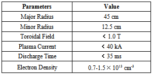
- The confinement and equilibrium of the plasma within the discharge chamber of a tokamak requires a suitably structured magnetic fields configuration. These magnetic fields will act as a magnetic tube only as long as especial conditions are satisfied. The confinement and equilibrium of the plasma within the discharge chamber of tokamak can be thought of as a problem of controlling the equilibrium position of the plasma column and the position of the plasma column with respect to its equilibrium position. If the equilibrium position of the plasma column can be made to be at the cross sectional center of the vacuum chamber, then a necessary condition for the plasma to be well confined is that the position of the plasma column from the center of the vacuum chamber be maintained to be less than a suitably small displacement. In the low beta tokamaks as IR-T1, radial pressure balance is achieved by the poloidal field, and toroidal force balance is achieved by the Lorentz force. But, in the toroidal force balance problem, if the two opposite forces are not equal, then plasma intend to shift inward or outward, which is dangerous for tokamak plasma equilibrium. Therefore, plasma equilibrium study is one of the fundamental problems of the magnetically confined plasmas. There are many available experimental methods and analytical solutions of the steady statemagnetohydrodynamics (MHD) equations, in particular, the Grad-Shafranov equation. Control of plasma position plays an important role in plasma confinement and the achievement of optimized tokamak plasma operation. Over the years different methods have been developed to analysis the tokamak plasma equilibrium and related problems[1-65].In this contribution we presented a current independent measurement of the plasma position in the IR-T1 tokamak, which is a small, air core, low beta, and large aspect ratio tokamak with a circular cross section (see Table 1). Details of this technique for the measurement of plasma displacement will be presented in section 2. Experimental results and comparison between them also will be presented in section 3. Also summary and conclusion will be discussed in section 4.
|
2. Current Independent Measurement of Plasma Position only Based on Poloidal Flux Loops
- Poloidal flux loops are a simple toroidally loops which measures the poloidal magnetic flux and an array of loops is usually used in control and reconstruction of plasma equilibrium states. The magnetic flux passing through such a loop is equal to
 , where
  represents magnetic poloidal flux. In the ohmically heated tokamaks, ohmic coils field is the main fraction of poloidal flux which passing through the flux loop. Therefore to obtain net poloidal flux due to plasma, compensation is required for all excessive flux. Because of large area of the flux loop, the inductive voltage is also large and then it consists of usually one turn. According to relation for frequency response, it is obvious that because of small self-inductance, frequency response of flux loop usually is higher than which desired. The magnetic probes are suitable for measurement of plasma position only in circular cross section plasma and not for elongated one, but the flux loops can be used in both elongated and circular section tokamaks. The plasma boundary in tokamaks is usually defined by Last Closed Flux Surface (LCFS). At the LCFS poloidal magnetic flux is constant, if we install some flux loops at some distance in vicinity of LCFS, then we can find plasma displacement from the difference in poloidal fluxes that received by the flux loops according to Shafranov equation. In the quasi-cylindrical coordinates
  for the poloidal magnetic flux we have[1].
 | (1) |
 and where
 are the plasma current, major and minor plasma radiuses, poloidal beta and internal inductance of the plasma. The relationship between poloidal magnetic flux and plasma displacement can be obtained:
 | (2) |
 | (3) |
 and
and  are the measurable magnetic fluxes by flux loops on outer surface of the vacuum chamber at mentioned polar angles, and where
  and
and  are the average magnetic fields between the outer and inner flux loops and the plasma surface respectively, which can be measured using the magnetic probes,
  is the intervening area for each loop defined as:
  , where
  is the distance between LCFS and each loop and
  is the distance between the midpoint (d/2) and center of the device. In the IR-T1 tokamak two poloidal flux loops were designed and installed on outer surface of the vacuum chamber in polar angles
  and
and  , with radiuses
  and
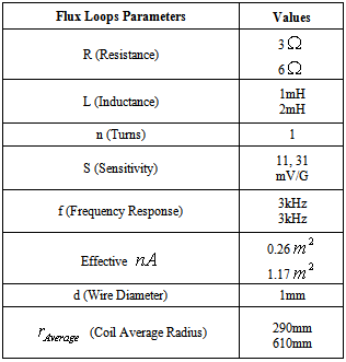
and  (see the Figure (1) and Table (2)). It is must be mentioned that the excessive fields such as toroidal field is the fraction of the poloidal flux which passing through the flux loops, therefore essentially compensation is needed. Compensation is done with dry runs technique. Experimental result for the measurement of plasma position using this technique will be presented in section 3.
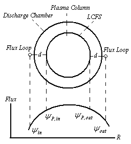 | Figure (1). Schematic diagram for the positions of two flux loops on outer surface of the IR-T1 tokamak, and also a qualitative plot of magnetic flux as a function of the radius |
|
3. Experimental Result and Comparison with Analytical Solution
- In order to determination of the plasma displacement based on this technique, we needed for the measurement of the poloidal magnetic flux around the plasma. As mentioned, we designed and installed two poloidal flux loops on outer surface of the IR-T1 chamber. Results of the measurement of time history of plasma horizontal displacement based on flux loops are presented in the Fig. (2b). In order to comparison of this result we presented the result of a method based on the analytical solution as shown in the Fig. (2c). Also plasma current is presented in the Fig. (1a). These figures show that the results are in good agreement with each other. Moreover, we plotted the magnetic flux surfaces for the plasma parameters at t=10ms in target shot, displacement of the plasma column center is clearly visible as shown in Fig. (3).
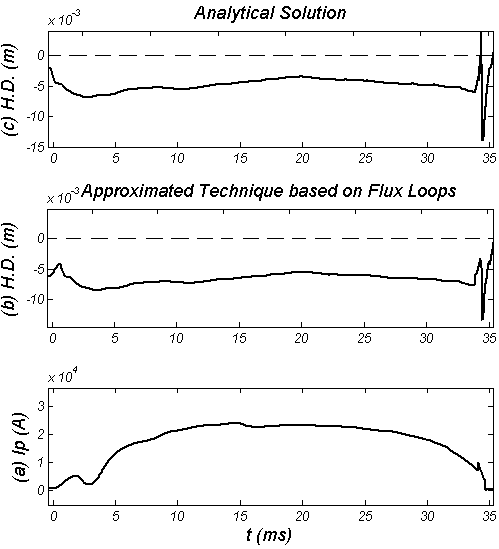 | Figure (2). (a) Plasma current, (b) Horizontal Displacement (H.D.) determined by the approximated technique based on flux loops, and (c) H.D. determined by the Analytical method |
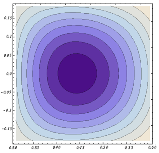 | Figure (3). Magnetic Flux Surfaces obtained by the Analytical Method at t=10ms in Target Shot in IR-T1 Tokamak |
4. Summary and Conclusions
- In this research we presented a good approximation for the measurement of plasma position especially based on two poloidal flux loops in the IR-T1 tokamak. The main advantage of this technique is that it based especially on the poloidal flux loops measurements (plasma current is not need). Based on this technique, two poloidal flux loops were designed and installed on outer surface of the IR-T1 tokamak chamber, and then the plasma displacement was measured from them. To compare the plasma displacement obtained using this method, analytical solution is also experimented on the IR-T1. The results of the two techniques are in good agreement with each other.The acceptable difference between them are because of (1) approximation in the measurement of desired magnetic flux on LCFS by the flux loops which installed on outer surface of the vacuum chamber and (2) possible errors in the compensation of excessive fields.