H. M. Mansour1, A. A. I. Khalil2, M. Y. Helali3, M. Mansour2
1Department of Physics, Faculty of Science, Cairo University, Giza, 12613, Egypt
2National Institute of Laser Enhanced Sciences, (NILES), Cairo University, Giza, 12613, Egypt
3National Research Institute of Astronomy and Geophysics, Helwan, Cairo, Egypt
Correspondence to: A. A. I. Khalil, National Institute of Laser Enhanced Sciences, (NILES), Cairo University, Giza, 12613, Egypt.
| Email: |  |
Copyright © 2012 Scientific & Academic Publishing. All Rights Reserved.
Abstract
A level of the Nd:YAG oscillator stability has been experimentally determined for different setups of resonator Q-switches. Performed experiments quantify an influence of an active modulation element on generated laser pulses stability. Different types of saturable absorbers were investigated and improved stability of double switching (active mode locker plus passive saturable absorber mode-locker) was confirmed. The best stability has been achieved with the aid of dual switching of an acousto-opticmodulator and a saturable absorber-dye solution 3955 in ethylalcohol to be used for satellite laser radar station at Helwan city in Egypt. The energy stability of the laser output can improve the accuracy and reliability of the satellite laser ranging station. The oscillator output picosecond pulses resulting from both the saturable absorber dye and three different multiple quantum well (semiconductor) saturable absorbers have been compared.Experimental results revealed that thedye ML51 mode-locking was suitable for Q-switched and mode-locked solid-state lasers.
Keywords:
Nd:YAG oscillator stability, Resonator Q-switches, Saturable absorbers, Mode-locked solid-state lasers, Satellite laser radar station
Cite this paper: H. M. Mansour, A. A. I. Khalil, M. Y. Helali, M. Mansour, Development of the Stability on the Laser System Used at Satellite Laser Ranging Station, Journal of Nuclear and Particle Physics, Vol. 4 No. 1, 2014, pp. 7-16. doi: 10.5923/j.jnpp.20140401.02.
1. Introduction
High-power, pulsed Nd:YAG laser is an attractive and promising system for many applications such as switching high voltage electric discharges, micromachining, micro- structuring, materials processing technologies, electronics and spectroscopy[1,2]. Active mode-locking involves the periodic modulation of the cavity losses or of the round-trip phase change, achieved e.g. with an acousto-optic or electro-optic modulator, a semiconductor electro-absorption modulator. If the modulation is synchronized with the cavity round trips, this leads to thegeneration of ultra-short pulses. The achieved pulse duration is governed by a balance of pulse shortening through the modulator[3,4] and pulse broadening via other effects, such as the limited gain bandwidth. Passive mode-locking (with a saturable absorber inside the laser resonator), it allows generating much shorter (femtosecond) pulses[5-7]. The pulse duration can be even well below the recovery time of the absorber; however passive mode-locking techniques for the generation of ultra-short pulse trains are preferred over active techniques due to the ease of incorporation of passive devices into various laser cavities. The liquid saturable absorber used for mode-locking and Q-switching is still considered to be the main drawback of passively mode-locked flash lamp pumped neodymium doped solid-state lasers[8-13]. In the following experimentthe output pulse trains are measured and compared between the use of only passive mode-locker, and the case where both passive (saturable dyes) and active mode-lockers (acousto-optic technique) are combined together. Also, the comparison between the mode-locked trains from multiple-quantum-well(MQW) No.758 and from liquid dye ML51 has been obtained.
2. Experimental Setup
The oscillator of the described system works in mode-locking regime as shown in Fig. 1. In this regime particular longitudinal modes of electromagnetic field in the oscillator are synchronized and thus it’s achieved ideally one shorter pulse in the oscillator. In this experiment common modulation of Q-factor was chosen, i.e. the modulation of losses in the resonator. To this reason, the special saturable absorber with short relaxation time can be used which, from certain intensity of absorbed energy, suddenly increases its transmission and thus decreases losses in the resonator. There exists also the second possibility of modulation, the acousto-optic modulator, a crystal, in which a periodical structure is established with the aid of applied high frequency field. On this structure the laser generated radiation is deflected.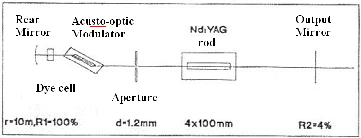 | Figure 1. Setup for the passive-active Q-switching of Nd:YAG laser oscillator |
By control of intensity of this field, a regulation of the Q-factor of the resonator can be reached. The open resonator of the oscillator consists of two mirrors: a high reflectance R1=100%, dielectric concave mirror M1 has a radius of curvature of r=10 m and a wedged mirror M2, which has a reflectance of 4% and its outer side has an antireflective coating for generated wavelength. An Nd:YAG crystal (4 x 100 mm) and a xenon flash lamp (7 x 75 mm) were placed in single-elliptical cavity with silver inner coating. A 1.2 mm shutter ensures a generation in a basic transverse mode. The resonator Q-factor is switched by the saturable absorber or double by the saturable absorber and the acousto-optic modulator. The resonator length was adjusted for acousto-optic modulator frequency of 94.75 MHz. The saturable absorber is made up of dye solution with such initial transmission which ensures generation of one burst of pulses. These solutions were used: ML51 in dichloroethan, 3955 in ethylalcohol and ML63 in ethylalcohol. This passive absorber was placed in a cell 5 mm thick near the high reflection mirror. The acousto-optic modulator was located in front of the cuvette. Its faces are cut in Brewster angle. This brings additional losses for one polarization (vertical to the scheme plane) and generated radiation is linearly polarized. In experiment with the aid of piezoelectric joule-meter (Gentec PRJ-M) measured output laser energy and with an oscilloscope (Tektronix TDS 350) voltage pulses are observed. Amplitude of these pulses is proportional to energy, which is in the burst of pulses. Response time of this detector is 25 ms, which ensures capturing of whole burst energy. With repetition rate of 5 Hz it doesn’t come to bursts interference. Nd:YAG laser system in Helwan SLR station consists of five parts: oscillator, pulse selector, amplifier chain (three Nd: YAG amplifiers), second harmonic generator, and the output telescope. Each of which has its own explanation in the followingsubsections. Figure 2 shows the different parts of the whole laser system. The flash lamp oscillator circuit is built from 120 µF capacitor bank and 22 µH inductance. In a free running mode, the cavity lasing threshold is 40 Joules; the mode-locking operating threshold is 45 joules. The pinhole diameter (1.6 mm) is placed near the rear concave mirror, and is working as a loss against the oscillation of transverse modes inside the cavity except of the TEM00 mode. The dye cell contains organic dye, e.g., ML51 dissolved in dichlorethan and it is used for Q-switching and mode-locking, the dye cell is placed next to the rear mirror because in this place it has the largest exposure volume to the laser radiation and this makes it to have a long life and not to be dissociated rapidly due to intense laser radiation, the dye cell contains 2 cc of dye solution. After the laser pulses exit from the oscillator output mirror they are reflected on the mirror M1, which is installed in the vertical plane at 45º with respect to the resonator axis, and then on M2 to pass through a telescope T1 to enlarge the spot diameter 3 times and a half wave plate which changes the horizontal polarization direction of the oscillator output 90 degrees, then we obtain vertically polarized mode-locked train of pulses which reflect on M3. The pulse selector consists of two Pockels cells installed between two crossed polarizer’s.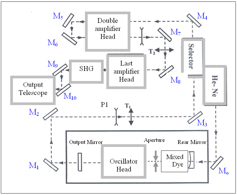 | Figure 2. Block diagram of the mode-locked Nd:YAG laser system: Mo - silver total reflecting mirror for the He-Ne laser, M1-M8 - total dielectric reflecting mirror for 1.06 µm radiation, M9 - dichroic mirror which reflects 0.53 µm and transmits 1.06 µm radiations, M10 - dielectric mirror totally reflecting radiation with the wavelength 0.53 µm |
Normally, no voltage is applied on these two cells, and therefore the train of pulses of vertical polarization is reflected from its direction by the 2ndGlann polarizer P2 and starts the switching part of the slicer via the photodiode PD. The transistor chain has been replacing a Krytron switch which has been found to produce too much noise in the electrical loop. The new transistor chain's switching level is arranged to switch just before the maximal pulse of the train, then the transistor chain gives the required quarter wave voltage on both Pockels cells, and the net effect of this operation is to rotate the plane of polarization of the linearly polarized light semi-train about 45º, to become circularly polarized one. And this is provided by passing the required pulses through the first pockel cell with quarter voltage applied on its electrodes. After passing the second pockel cell, the plane of polarization is again rotated about 45º. After the output pulse or semi-train of pulses exit from the second pockel cell to the second Glann polarizer, the quarter-wave voltage is removed from the pockel cells and the rest of the pulses from the train is again reflected by the Glann polarizer. The amplifier chain consisted of three Nd:YAG crystals with the diameter of 7 mm, and length of 120 mm. Two of them are placed in a single gold-plated double elliptical cavity and been pumped by a single xenon flashlamp. The rod of the last amplifier is placed in an elliptical silver coated cavity, and of its length, a 100 mm is being pumped by one xenon flash lamp. Before entering the last amplifier the laser beam is expanded twice by the telescope T2. The amplification of the last amplifier is 10 times, resulting in 100 mJ output energy in the spot of diameter 5 mm and for input pumping energy for the last amplifier of 60 J. The oscillator output pulse's duration is further compressed due to the frequency doubling by the KDP nonlinear crystal to become 17 ps in the green. The power conversion efficiency has been found to be 50 %. The beam is expanded 2.5 times, and the output beam divergence could be adjusted through the range 0.1–1 milliradians according to which distance we want the beam to travel to the satellite, in order to obtain a reasonable and enough reflected signals from the satellite retro-reflectors as shown in Fig. 3. The laser pulses from the output telescope are directed by other four Code' mirrors to exit the mount in the direction of the satellite, and follow its orbit automatically with slight motor corrections during tracking, when required. These corrections could be easily determined by tracking a star near the same direction and adjusting the beam on it, then see the error and use it later with the satellite at or near the same direction of the star. The main units controlling this operation are the PC, and the LRE (Laser Ranging Electronics) which provide the laser system power supplies with triggers, and the Azimuth-Elevation steeper motors of the mount with the calculated orbital data (Ephemeris) as a function of time, which should be previously fed to the especially-prepared satellite ranging PC- programs. The saturation process in MQWs can be better quantified by the pulse fluence  than by the intensity I because of the limited relaxation time
 To minimize the losses, the absorber should be saturable with the expected pulse fluence
 . Another limitation is the damage threshold of the MQWs. A typical saturation
  is about 70 µJ/cm2. In the laser cavity the incident pulse fluence
 can be adjusted by varying the illuminated area on the MQWs. If the intracavity pulse power is low, e.g. because of low pump power, then tighter focusing helps to achieve the necessary saturation
  The saturable absorption A of the MQWs can be calculated by:
 | (1) |
where,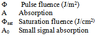
 | Figure 3. The outer part (Mount) of the automatic, Nd:YAG laser station |
Figure 4 shows the saturable absorption A as a function of the fluence at constant  The pulse fluence
  can be derived from the mean output power P as follows
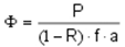 | (2) |
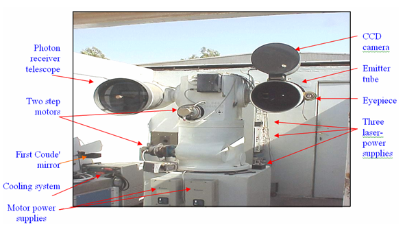
where, Pulse fluence (measured in J/cm2)P Mean output power of the laserR Reflectance of the output mirror f Repetition rate of the laser aIlluminated area on the MQWs
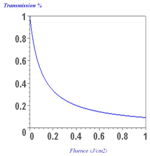 | Figure 4. Shows the transmission as a function of the fluencyat constant A0 = 1 % and Φsat = 0.1 mJ/cm2[14] |
From Heisenberg's uncertainty principle for the conjugated variables pulse width  and photon energy
  The TBWP (time bandwidth product) of a laser pulse is limited to about
  Where h is a Planck's constant
  is the pulse mean frequency and
  is the pulse bandwidth.An accurate calculation can show that the minimum TBWP for a Gaussian pulse is
  0.44 (pulse duration in seconds multiplied by the pulse bandwidthin
  The minimum TBWP for a Sech2 pulse is
  Using the relation
 the frequency interval
  is related to the wavelength interval
  by,
by, Where,c ≈ 2.988 x 10⁸ m/s is the speed of light in the vacuum.For passive mode-locking by MQWs, the saturation of absorption for high incident intensity is essential. Therefore, nonlinear characteristics of the absorbers were studied practically using a similar multiple-quantum-well (MQWs) structures that were grown on 400 µm thick GaAs substrate at Center for High Technology Materials, University of New Mexico, by MBE method. They have 100 periods of InxGa1-xAs (x = 0.2) thickness of 8 nm, between two GaAs layers, each 10 nm thick. As a light source they used microchip diode pumped solid state laser Nanolase NP-02012-100 generating 810 ps long pulses with energy of 2.9 µJ at repetition rate of 15.3 kHz. The output radiation at average power of 44 mW was focused using a positive lens with focal distance of 50 mm. The insertion of the sample at various distance from the focal point enabled the change of the incident power density on the MQWs sample[15]. The output power from the laser was attenuated in order not to damage the MQWs; the maximum power density in the focal point was 10 MW/cm2. The initial low power transmission of 23% far from the focal point increases to the 45% close to the focal point, the transmission of the GaAs plate alone was 52%, which means that non-saturable losses in MQWs were about 10% was mainly due to beam defocusing in GaAs[16]. The Nd:YAG laser system oscillator at Helwan SLR is used to test the three MQWs semiconductor saturable absorbers as shown in Fig. 5. Each MQW sample is installed independently at about 450 with the resonator axis and the dye cell is filled only with dichloroethan in the presence of MQWs. The full output (mode-locked) train from the oscillator is directed via the system laser mirrors to a photodiode which is connected to oscilloscope.
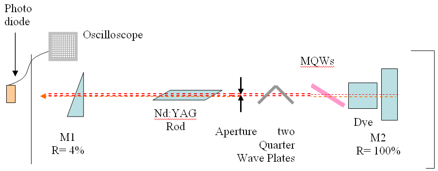 | Figure 5. Setup for MQW saturable absorber, mode-locking |
3. Results and Discussions
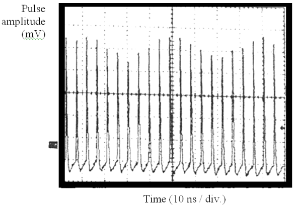
For each dye solution the energetic stability of the output burst from the oscillator was measured. In the first case only passive and in the second case passive and active switch of the Q-factor was used. Fig. 6 and Fig. 7 showthe bursts of output pulses. Fig. 6shows the passive modulation of the resonator (saturable absorber- dye 3955 in ethylalcohol) while Fig. 7 shows the passive (with the same saturable absorber) and also active modulation. An energy stability and also general laser stability is perceptible. Each flash of the flash lamp is followed by laser action (there is no pulse drop out). Fig. 8 and Fig. 9 show the same bursts in 50-multiple exposition, which also demonstrates the oscillator stability. Fig. 10a – f. show a statistic division as well as histograms. A measured energy is placed on horizontal axis and normalized percent of occurrence on vertical axis. Then each histogram is completed with percentage dispersion of observed quantity for the given oscillator configuration.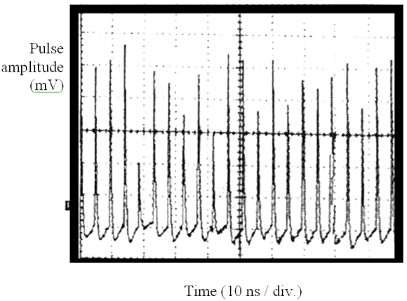 | Figure 6. The energetic stability of the oscillator output, 21 successive pulses, passive modulation- dye 3955 in ethylalcohol, vertical scale: 5 mV/ div |
 | Figure 7. The energetic stability of the oscillator output, 21 successive pulses, passive (dye 3955 in ethylalcohol) + active modulation, vertical scale: 5 mV/ div |
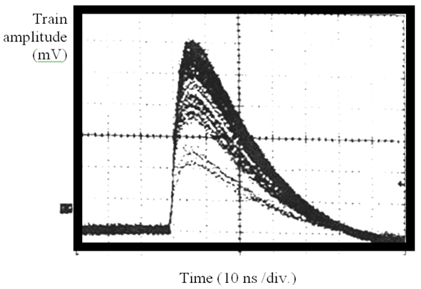 | Figure 8. Energetic stability of oscillator output – 50 multiple expositions. passive modulation – dye 3955 in ethylalcohol,vertical scale:5 Mv/ div |
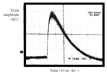 | Figure 9. Energetic stability of oscillator output - 50 multiple expositions. passive modulation – dye 3955 in ethylalcohol + active modulation,vertical scale: 5 mV/ div |
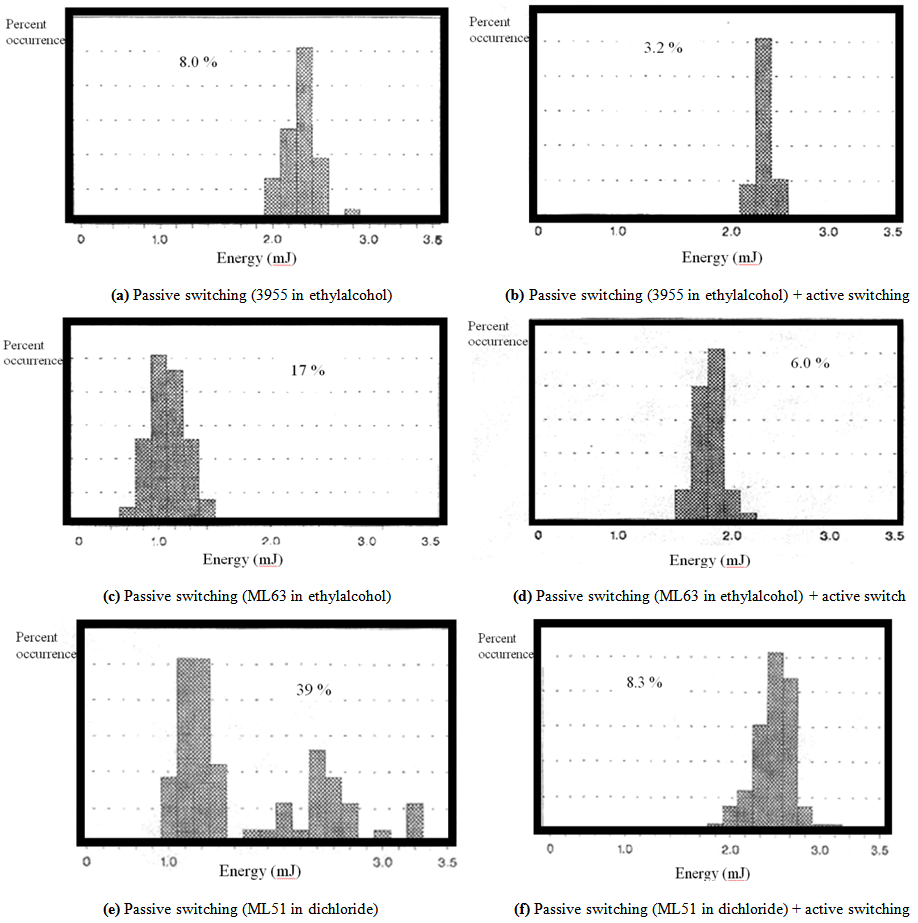 | Figure 10. Histograms of bursts energy distribution |
3.1. Oscillator output
The output from the oscillator is trains of TEM00 mode-locked pulses of wavelength 1064 nm and of 24 ps FWHM measured by streak camera, its repetition rate is 5 Hz and having energy of about 1 mJ in single pulses, about 8 mJ per train of pulses, the pulses are separated by the roundtrip time interval of 6 ns (the length of the oscillator is 0.90 m), the time resolution of the streak camera was 1.4 ps. However, the oscillator output could vary both quantitatively (number of pulses per train) and qualitatively (energy and time duration of pulses as well as the envelope of the train) the reason is the flash lamp input energy and the type of Q-switch, the Q-switch is a liquid dye. Also various experimental parameters such as the type of dye, its initial transmission, and its circulation speed inside the cell play important roles.
3.1.1. Output Energy Stability
The amplifiers in laser cavity affect the stability of output parameters only if they are in saturation and thus fluctuations are restricted higher from the certain level of the signal. The optimum working dye (ML51) - circulation voltage and the stability of the mode-locked pulse energy have been measured, and new mode-lockers have been investigated.
3.1.1.1. Optimum Dye-circulation Voltage
The dye-solution must circulate inside the cell prior to and during the laser system operation in order to keep working fast and properly, for this reason a simple experiment was done to measure the optimum circulation voltage for the dye ML51 of anonymous initial transmission, T. The Photodiode and the station calibration program can calculate the number of received laser shots by the photo detector and the number of applied external laser triggers to the flash lamp. The dye circulation inside the cell at Egyptian Helwan station is accomplished by a small motor of variable speed, fixed in a vertical position with a small magnet fixed with its rotating axis. Both are located in a cavity under the dye cell, with its rotating magnet up and just below the dye cell, another small cylindrical magnet is located inside the dye cell. When the motor is on, the magnet connected to the motor axis rotates under the dye cell and, therefore making the other magnet inside the dye cell to rotate in the same direction, hence circulating the dye inside the cell. The efficiency of the dye, clearly, depends on its circulation speed, because when the dye circulation was too slow (applied voltage < 6 volts) many laser shots were lost from the output with the appearance of noise mainly due to incomplete mode-locking. Figure 11 shows the average number of successful laser shots per 1000 triggers versus the applied voltage to the mixing motor. On the other hand, when the voltage was higher than 12 Volts, i.e., the dye circulating was very fast, there had been a sudden output drop to below 15% between 12 and 13 volts, and then rises again to above 40% near 14 Volts, and after that it decreases fast to reach 10% output at near 16 volts. It is foundthat the optimum circulation speed of the dye was at 11-12 volts range as input for the rotating motor, as the output complete-laser shots per 1000 triggers reached 99% only in this range.Nevertheless, it could circulate with a fairly well output in the range of 6-12 voltswith a maximum loss of 3% only as seen from the behavior of the plateau in Fig. 11.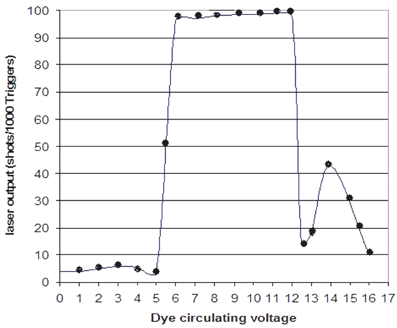 | Figure 11. The average number of successful laser shots per 1000 triggers versus the applied voltage to the motor |
3.1.1.2. Effect of Dye Transmission and Input Electrical Energy on the Output Energy
The average laser output energy Eout(av.) is calculated for every 10 readings of the energy meter taken for each dye transmission. The same procedure was made for 7 different input electrical energy values. The results are plotted in Fig. 12 versus the flash lamp input electrical energy Ein for three different transmissions (25%, 30%, and 40%) of the dye ML51 dissolved in dichlorethan.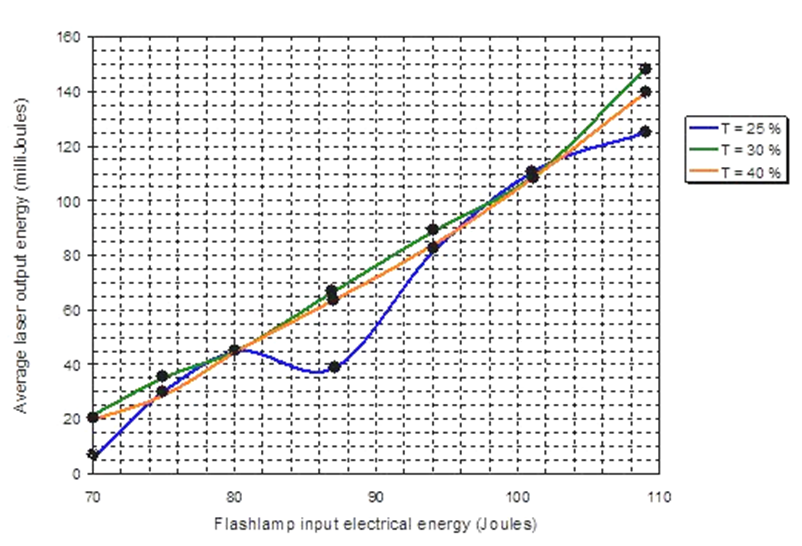 | Figure 12. The change of the output laser energy per train with the input pumping energy for three different initial dye transmissions; 25 %( the blue line), 30% (the green line), and 40 % (the red line) |
Figure 12 shows the output laser energy shows a nonlinear behavior with the input flash lamp energy at lower initial dye transmission 25%. As the dye initial transmission increases 30% and 40% however the change appears to be more linear. It is also noticed that all the used dye transmissions, result in the same output energies at two flash lamp input energies, and this is clear from the two intersection points between the three curves representing the three dye transmissions together at around (80 J, 45 mJ), and near to (102 J, 115 mJ). The lower dye transmission, 25%, gives, in average the least value of output energy, then that of 40%, and the greater average value is obtained from the 30% dye transmission for the dye ML51 used in the selected range from 70 to 109 J of the input flashlamp energy. Furthermore the curve at 25% transmission suffers from big variations in the output energy in the ranges of input energy 70-74 J; 80-94 J; and also 104 to above 108 J, however the output energy for this dye transmission only exceeds that from the other two in the range of 98-102 J of flashlamp input energy. The other two curves for the dye transmissions 30%, and 40% shows greater average output energy and much better output energy stability. Fromthese experiments, columns A, B, and C as shown in Fig. 13, three average train samples from each sample of the MQWs 758, 1487, and 2313 respectively are obtained. It can be seen that the MQWs sample No.758 (column A) gives mode-locked trains of reasonable symmetry and greater amplitude (energy), (peak pulse: 1.2 to 1.4 volts on the oscilloscope scale) than the other two MQWs (columns B and C) which results in mode-locked pulse trains of less symmetry and of less peak voltage. The resulting mode-locked trains from liquid dye ML51(A), and from MQW number 758 saturable absorber (B), are compared as shown in Fig. 14. It is found that the dye ML51 mode-locking gives an average peak pulse of about twice that resulting from MQW sample No.758.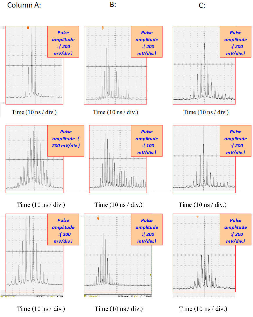 | Figure 13. Mode-locked train results when: (A), MQW No. 758; (B), MQW No. 1487; (C), MQW No. 2313 were introduced inside the Helwan SLR laser system-resonator as a passive mode-locker |
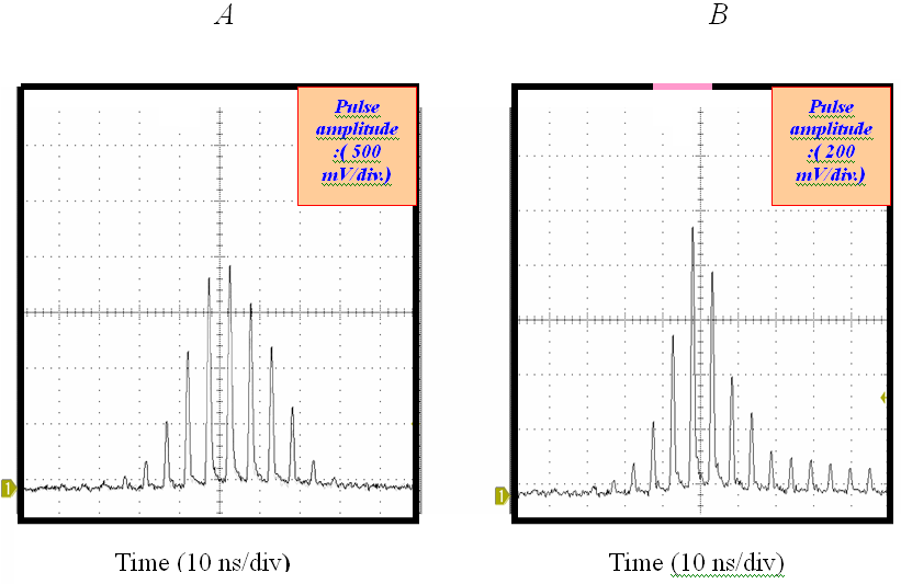 | Figure 14. Mode-locked train when: (A) dye ML51, and (B) MQW No.758 were used |
4. Conclusions
The goal of this work was to develop the construction of the Helwan SLR laser system in Egypt, to measure its output energy stability fromthe saturable absorber dye ML51 at three different concentrations in dichlorethan and from different pumping energies, and at the optimum dye circulation speed. The research measurement of Q-switches here was made on the bases of the laser radar. Double switching experiments: showed that the best result was reached when the acousto-optic modulator and the dye solution 3955 in ethylalcohol (percent occurrence 3.2%) were used together. From the statistic division of the measured bursts energies, one can conclude that the resonator stability is increased by factor of about 2.5 times, when dual switch of the Q-factor is used.It can be seen that the MQW No.758 gives mode-locked trains of reasonable symmetry and greater energy, (peak pulse: 1.2 to 1.4 volts) than the other two MQWs. Furthermore, the dye ML51 gives an average peak of about 1.8 volts while the MQW No.758 gives a train of peak pulse less than 1 volt and of less symmetrical than that of the dye ML51 mode-locker. Therefore, the organic dye ML51 is better than the semiconductor MQW saturable absorbers for mode-locking HelwanNd:YAG laser system for SLR purpose because the small energy in the train means insufficient power of the laser beam and therefore inability to track even the low orbit satellites especially at lower elevations because of the high atmospheric losses.
ACKNOWLEDGMENTS
Authors would like to thank Prof. Dr. A. Novotny for fruitful discussions.
References
| [1] | A. A. I. Khaliland M. C. Richardson, "Generation of ion beams on a steel surface by laser radiation at various wavelengths under the presence of an applied electric field". Laser Phys Lett.3(3), 137-144 (2006). |
| [2] | A. A. I. Khalil, "Spectroscopic studies of UV lead plasmas produced by single and double pulse laser excitation". Laser Phys. 23,015701(2013). |
| [3] | Ji-ying Peng, Bao-shan Wang, Yong-gang Wang, Jie-guang Miao, Hui-ming Tan, Long-sheng Qian and Xiao-yu Ma, "Q-switched and mode-locked diode-pumped Nd: YVO4 laser with an intracavity composite semiconductor saturable absorber". Optics & Laser Tech. 40(2), 243-246 (2008). |
| [4] | G. Xiao and M. Bass, "A generalized model for passively Q-switched laser including excited state absorption in the saturable absorber". IEEE J Quantum Electron, 33 (1), 41–44 (1997). |
| [5] | H. Jelínková, P. Cerny, J. Šulca, J. K. Jabczynski, K. Kopczynski, Z. Mierczyk, M. Miyagi, Y. Matsuura, and Y.-W. Shi,"Nd: YAP 1.34 um/1.08 um laser passively mode-locked and Q-switched by V3+:YAG/BDN II saturable absorbers with efficient radiation delivery through a hollow glass waveguide coated with COP/Ag". Opt Eng.41(8), 1976-1982 (2002). |
| [6] | J. K.Jabczynski, W. Zendzian, J. Kwiatkowski, V. Kubecek, H. Jelinkova, A. Stintz and J. C. Diels,"Picosecond Nd:YAG slab laser passively Q-switched and mode-locked, using multiple quantum well saturable absorbers". SPIE, 6731, 67312I (2007). |
| [7] | Y.Tang, A. Siahmakoun, G. Sergio, M. Guina and M. Pessa, "Opticalswitching in a resonant Fabry–Perot saturable absorber". J Opt A: Pure Appl. Opt.8, 992 (2006). |
| [8] | V. Kubecek, J. Biegert, J-C Diels and M. R.Kokta,"Practical source of 50 ps pulses using a flashlamp pumped Nd:YAG laser and passive all-solid state pulse control". Opt Commun. 177(1-6): 317-321 (2000). |
| [9] | U. Keller, "Ultrafast all-solid-state laser technology". Appl. Phys. B, 58, 347-363 (1994). |
| [10] | J. Biegert, J-C. Diels, K. Malloy, A. Stintz, V. Kubecek, "42 ps pulses from a flashlamp pumped Nd:YAG laser using all-solid-state passive pulse control".Conference Digest, Conference on Lasers and Electro- Optics Europe, IEEE Cat. No. 00TH8505, 115 (2000). |
| [11] | A. M. Malyarevich, V. G. Savitski, P. V. Prokodshin, N. N. Posnov, K. V. Yumashev, E. Raben, A. A. Zhilin,"Glass doped with PbS quantum dots as a saturable absorber for 1-m neodymiumLasers". JOSA B, 19,28-31 (2002). |
| [12] | A. A. I. Khalil, "A comparative spectroscopic study of single and dual pulse laser produced UV tin plasmas". Opt. & Laser Tech. 45, 443-452 (2013). |
| [13] | V. Kubecek, J. Biegert, J-C.Diels, A. Dombrovsky, K. Malloy and A. Stintz,"Picosecond flashlamp pumped Nd:YAG laser using all-solid-state passive pulse control". Proc. of SPIE, 4424, 151-154 (2001). |
| [14] | Batop company of optoelectronic devices,http://www.batop.com |
| [15] | R. Schwedler, H. Mikkelsen, K. Wolter, D. Laschet, J. Hergeth and H. Kurz, Institut fur Halbleitertechnik, RWTH Aachen Sommerfeldstrasse 24, 52074 Aachen, Germany, "In GaAs/InP multiple quantum well modulators in experiment and theory".J. Phys. III France,2341 (1994). |
| [16] | V. Kubecek, H. Jelínková, A. Dombrovský,A. Stintz, J. Diels. "Flashlamp pumped oscillator-amplifier Nd: YAG system mode locked using multiple quantum well saturable absorber". presented at Solid State Lasers conference 5460-15, part of Photonics Europe, Strasbourg, 26-30, Technical program, 195 (2004). |
 Abstract
 Reference
 Full-Text PDF
 Full-text HTML