A. Paknezhad 1, A. Salar Elahi 2, M. Ghoranneviss 2
1Physics Department, Shabestar Branch-Islamic Azad University, Shabestar, Iran
2Plasma Physics Research Center, Tehran Science and Research Branch, Islamic Azad University, Tehran, Iran
Correspondence to: A. Paknezhad , Physics Department, Shabestar Branch-Islamic Azad University, Shabestar, Iran.
| Email: |  |
Copyright © 2012 Scientific & Academic Publishing. All Rights Reserved.
Abstract
We measured the plasma column shift using array of magnetic pick-up coils (magnetic probes) and compared with analytical solution in the IR-T1 tokamak. In the first technique, four magnetic probes were designed, constructed, and installed on outer surface of the IR-T1 tokamak chamber and then plasma column displacement determined from them. To compare the results obtained using this method analytical solution of the Grad-Shafranov equation based on expansion of free functions as quadratic in flux function is also experimented on IR-T1. Results of the two techniques are in good agreement with each other.
Keywords:
Tokamak, Plasma Column Shift, Magnetic Pick-up Coils, Grad-Shafranov Equation
Cite this paper: A. Paknezhad , A. Salar Elahi , M. Ghoranneviss , Comparison between the Magnetic Probes and Analytical Method in Measurement of the Shafranov Shift, Journal of Nuclear and Particle Physics, Vol. 3 No. 5, 2013, pp. 127-131. doi: 10.5923/j.jnpp.20130305.01.
1. Introduction
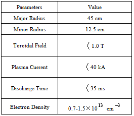
In the low beta tokamaks, radial pressure balance is achieved by the poloidal field, and toroidal force balance is achieved by the Lorentz force. But, in the second one, plasma may intend to shift inward or outward, which is a very dangerous for tokamak plasma. Therefore, plasma equilibrium study is one of the fundamental problems of the magnetically confined plasmas. There are many available global solutions of the steady state magnetohydrodynamics equations, in particular, the Grad-Shafranov equation. Control of plasma position plays an important role in plasma confinement and to achieve optimized tokamak plasma operation. Accurate determination of the plasma position during confinement time is essential to transport it to a control system based on feedback. Over the years different methods have been developed to analyze the equilibrium problems and determining the plasma column shift[1-10].In this paper we presented magnetic probes method for measurement of the plasma column shift and comparison with analytical solution of Grad-Shafranov equation in the IR-T1 Tokamak, which is a small, air core, low beta and large aspect ratio tokamak with a circular cross section, (see Table 1). Details of the magnetic probes method for determination of plasma column shift will be discussed in section 2. Analytical solution of the Grad-Shafranov equation will be presented in section 3. Experimental results and comparison between them also will be presented in section 4. Summary and conclusion are also will be presented in section 5.
2. Magnetic Probes Technique for Measurement of the Plasma Column Shift
Because of dependence of the plasma position and plasma current distribution to magnetic field distributions around the plasma, therefore magnetic pickup coils give us information about the plasma position or plasma column shift,  . Poloidal and normal magnetic fields distributions around the plasma are[1]:
 | (1) |
 | (2) |
Therefore, by rearranging the above equations the first relation for plasma column shift obtained: | (3) |
where we used the quasi-cylindrical coordinates ( ). Equations (1) and (2) accurate for the low beta, large aspect ratio and circular cross section tokamaks as IR-T1, and where:
 | (4) |
According to this approach, in the IR-T1 tokamak four magnetic probes were designed, constructed, and installed, two magnetic probes were located on the circular contour  of the radius
  in angles of
  and
and  to detect the tangential component of the magnetic field
  and two magnetic probes are also located above,
  , and below,
  , to detect the normal component of the magnetic field
  , as shown in Figure (1).By substituting the poloidal and normal components of the magnetic field which obtained by four magnetic pickup coils (after compensation and integration of their output), in Eq. (3), displacement of the plasma column boundary was determined. Experimental results will be presented in section 4.
 | Figure (1). Positions of the four magnetic probes on the outer surface of the IR-T1 tokamak chamber |
3. Analytical Solution of the Grad-Shafranov Equation
For axially symmetric configurations, Maxwell's equations together with the force balance equation from MagnetoHydroDynamics (MHD) equations, for stationary and ideally conducting plasmas, reduce to the two-dimensional, nonlinear, elliptic partial differential equation, or Grad-Shafranov equation (GSE)[2]: | (5) |
where
 | (6) |
and where  and
and  are two free functions.Many authors solved the Grad-Shafranov equation by expanding the free functions on different order in
  . In this section, we present quadratic order (which proposed by Guazzotto[3]), and examined on the IR-T1.If we choose the free functions to be quadratic in
  as[3]:
 | (7) |
where  on magnetic surfaces axis,
  is the major radius, and
  is the vacuum toroidal field.The Grad-Shafranov equation reduces to:
 | (8) |
where  . With normalizing variables as
  , and
, and  , Eq. (8) can then be written as:
 | (9) |
where  , is the inverse aspect ratio, and
 | (10) |
The solution of Eq. (9) in cylindrical coordinates  can be written as:
 | (11) |
where  , and for up-down symmetric case,
  obtained as:
 | (12) |
Also  can be written as:
 | (13) |
where  ,
,  , and
, and  are the Whittaker functions, and in this model
  . Guazzotto proposed only three terms for m, and then
  can be written as:
 | (14) |
where  are nine unknown coefficients which must be determined. The first six of them can be obtained from boundary conditions. The boundary conditions for the points of inner, outer, and top of the plasma cross section are (see Figure (2))[3]:
 | (15) |
and condition for right convexity on the inboard midplane is: | (16) |
also two conditions, one defining the location of the magnetic axis ( ) and the other the normalization for
  on magnetic axis:
 | (17) |
 | Figure (2). geometry used for the boundary conditions |
These are seven boundary conditions for seven unknown coefficients  But for other three coefficients, by setting
  (the simplest solution for GSE independent of
  ), and introduce one approximate value for the
  (
( , negative for diamagnetism plasma), and assuming that
  be imaginary and
  be real, the values of
  can be determined by minimizing the error function between traditional plasma shape (
 ), and analytical plasma shape. Appropriate error function between them defined as follow[3]:
 | (18) |
where subscripts  indicates the analytical and traditional plasma shape parameters respectively, and sum in minimum include 3 angles (
 ) for our purpose (circular plasma).In general by minimizing the error function (e.g. by Mathematica) as possible to zero, and finding optimal values for
  and also solving seven equations for the boundary conditions (Eqs. (15), (16), and (17)), six unknown coefficients (
 ), moreover
  can be find. Therefore the magnetic flux surfaces can be plot by substituting these nine coefficients and also input parameters as
  in Eq. (14). Moreover the Shafranov shift (
 ), is also can be obtained by subtracting
  We repeat 18 times this procedure for different approximate values for
  during time interval of target shot (for example the magnetic flux surfaces at t=15ms correspond to
  shown in Figure (5)), and obtaining time interval of Shafranov shift. Results were shown in Figure (4).
4. Experimental Results and Comparison between Them
For determination of the Shafranov shift using the magnetic probes method, we needed for determination of the magnetic field distribution around the plasma. Therefore we designed, and constructed a four magnetic pickup coils, and installed them on outer surface of the IR-T1 chamber. Positions of the four magnetic probes on the outer surface of the IR-T1 chamber were shown in figure (1). Also, plasma current obtained from the Rogowski coil.The electric circuit used for the measurement of the induced voltage that is supplied by the magnetic probes is showed in Figure (3):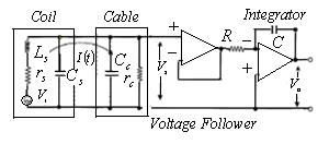 | Figure (3). Block diagram of the circuit for magnetic probe |
In the diagram,  is the current in the coil circuit and
  is the coaxial cable output signal. The application of Kirchhoff’s voltage law for this circuit yields the following equation:
 | (19) |
where,  is the probe resistivity,
  is the cable resistivity and
  probe self-inductance. So, the integrator output
  for steady state current given by
  | (20) |
where  is the integrator time constant, and where
  is the inductive voltage supplied by each one of the magnetic probes. We used the two methods to determine the Shafranov shift in IR-T1 tokamak, and results presented in Figure (4). These figures show that results of two methods are in good agreement with each other. Moreover we plot the magnetic flux surfaces for plasma parameters at t=15ms in target shot on IR-T1 tokamak, as we expect there is displacement of plasma column center as shown in Figure (5).
Table 1. Parameters of the IR-T1 Tokamak
 |
| |
|
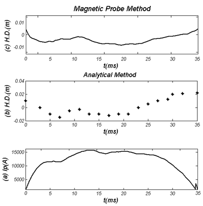 | Figure (4). (a) Plasma current, (b) Horizontal Displacement (H.D.) determined by the Analytical method, and (c) H.D. obtained by the magnetic probes method along the plasma current |
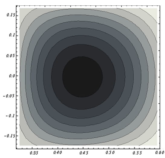 | Figure (5). Magnetic Flux Surfaces obtained by the Second Analytical Method at t=15ms in Target Shot correspond to  on IR-T1 Tokamak, Displacement of the Plasma Column Center observable on IR-T1 Tokamak, Displacement of the Plasma Column Center observable |
5. Summary and Conclusions
In this paper we presented magnetic probes technique for measurement of the Shafranov shift and comparing with analytical technique in the IR-T1 tokamak. In the first technique, four magnetic pickup coils were designed, constructed, and installed on outer surface of the IR-T1 tokamak chamber and then, plasma displacement measured from them. To compare the results measured using this method analytical solution of the Grad-Shafranov equation based on expansion of free functions as quadratic in flux function is also experimented on the IR-T1. Results of the two techniques are in good agreement with each other. The acceptable differences between them are because of (1) approximation in measurements of magnetic fields distribution because of discrete probes measurements, (2) the approximate values chosen for  , and (3) the errors do not become zero during minimizing the error function.
References
| [1] | K. Nakamura and M. Ghoranneviss, Fusion Eng. Des. 66-68 (2003) 771-777. |
| [2] | V. S. Mukhovatov and V. D. Shafranov, Nucl. Fusion 11, (1971), 605 |
| [3] | I. P. Shkarofsky, Phys. Fluids 25 (1) 89-96, (1982). |
| [4] | G.S. Lee and and M. Ghoranneviss, Nucl. Fusion 41, 1515 (2001) |
| [5] | S.H. Seo, Phys. Plasmas 16, 032501 (2009) |
| [6] | A. Salar Elahi and M. Ghoranneviss, IEEE Trans. Plasma Science 38 (2), 181-185, (2010) |
| [7] | A. Salar Elahi and M. Ghoranneviss, IEEE Trans. Plasma Science 38 (9), 3163-3167, (2010) |
| [8] | A. Salar Elahi and M. Ghoranneviss, J. Plasma Physics 76 (1), 1-8, (2009) |
| [9] | A. Salar Elahi and M. Ghoranneviss, Fusion Engineering and Design 85, 724–727, (2010) |
| [10] | A. Salar Elahi and M. Ghoranneviss, Phys. Scripta 80, 045501, (2009) |
 Abstract
 Reference
 Full-Text PDF
 Full-text HTML