A. Paknezhad1, M. Ghoranneviss2, Ahmad Salar Elahi2, R. Arvin2, S. Mohammadi2
1Physics Department, Shabestar Branch-Islamic Azad University, Shabestar, Iran
2Plasma Physics Research Center, Science and Research Branch, Islamic Azad University, Tehran, Iran
Correspondence to: A. Paknezhad, Physics Department, Shabestar Branch-Islamic Azad University, Shabestar, Iran.
| Email: |  |
Copyright © 2012 Scientific & Academic Publishing. All Rights Reserved.
Abstract
Precision measurements of the Shafranov parameter and Shafranov shift are essential in tokamak plasma studies. In this contribution we calculated the current independent relations for the Shafranov parameter, and then investigated and compared the technical and theoretical points for the measurements of these parameters. We presented two comparative techniques for the measurement of Shafranov parameter and also two comparative techniques for the measurement of Shafranov shift. For the first purpose, two flux loops were designed and installed on outer surface of the IR-T1 chamber, and then a poloidal flux and the Shafranov parameter measured from them. To compare the results, four magnetic probes were designed and installed on outer surface of the IR-T1, and again the value of Shafranov parameter independently was measured. For the second purpose, a modified Rogowski and Saddle Sine coils were designed, constructed, and installed on outer surface of the IR-T1 chamber and Shafranov shift were measured from them. To compare the plasma position measured using this technique, a method based on the analytical solution is also examined on the IR-T1. Results compared and discussed.
Keywords:
Keywords Tokamak, Shafranov Parameter, Shafranov Shift
Cite this paper: A. Paknezhad, M. Ghoranneviss, Ahmad Salar Elahi, R. Arvin, S. Mohammadi, Approaches on Measurements of the Shafranov Parameter and Plasma Displacement in Tokamaks, Journal of Nuclear and Particle Physics, Vol. 3 No. 4, 2013, pp. 55-62. doi: 10.5923/j.jnpp.20130304.02.
1. Introduction
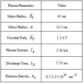
Shafranov parameter (asymmetry factor) and Shafranov shift are two of main parameters of the tokamaks plasma. From these parameters, many of the tokamak plasma informations such as poloidal beta, internal inductance, current density profile, plasma pressure, and energy confinement time can be determined. From the measurement of poloidal magnetic flux around the plasma, for example with flux loops, we can find the Shafranov parameter. On the other hand, distribution of magnetic fields around the plasma relate to the Shafranov parameter which can be measured with magnetic probes. Although magnetic probes suitable for the measurement of Shafranov parameter and then plasma position only in circular cross section plasma and not for elongated one, but a set of flux loops either in elongated and or circular cross section tokamaks can be used. In this contribution we calculated the current independent relations for the Shafranov parameter, and based on these relations we presented a comparison between a poloidal flux loops and magnetic probes in the measurement of the Shafranov parameter in IR-T1 tokamak, which is a small, air core, low beta and large aspect ratio tokamak with a circular cross section, (see Table 1). Table (1). Basic parameters of the IR-T1 tokamak
 |
| |
|
Also in this research we presented two techniques based on the theoretical and technical points for the measurement of plasma column displacement in IR-T1 tokamak. Control of plasma position has important role in plasma confinement and to achieve optimized tokamak plasma operation. It is known that in ohmically heated tokamaks, radial pressure balance is achieved by the poloidal field, and also toroidal force balance is achieved by interaction of the external vertical field with toroidal current (when inward Lorentz force equal with sum of the three outward forces (hoop force, tire tube force, and 1/R force) due to the toroidal configuration of the tokamak). But, in toroidal force balance problem, the two opposite forces may be not equal, and therefore plasma intend to shift inward or outward, which is dangerous for tokamak plasma[1-17]. Therefore, we also investigated and compared the theoretical and technical points for the measurement of Shafranov shift in the IR-T1 based on the multipole moments and analytical solution of the Grad-Shafranov equation. Details of the poloidal flux loop and magnetic probes techniques for the determination of Shafranov parameter will be discussed in section 2. Theoretical approach of multipole moments method for the measurement of plasma column displacement will be discussed in section 3. A method based on the analytical solution of Grad-Shafranov equation for the measurement of Shafranov shift will be presented in section 4. Details of design and fabrication of modified Rogowski and Saddle Sine coils, flux loops, and magnetic probes will be discussed in section 5. Experimental results and comparison between them will be presented in section 6. Summary is also will be discussed in section 7.
2. Poloidal Flux Loops and Magnetic Probes Methods for Determination of the Shafranov Parameter
Poloidal flux loop is a simple toroidally loop which measure the poloidal magnetic flux and usually array of them use in control and reconstruction of plasma equilibrium states. The magnetic flux passing through such a loop is equal to  , where
  represent to magnetic poloidal flux. It is must be mentioned that the excessive fields are a fraction of poloidal flux which passing through the flux loop. Therefore to measure net poloidal flux due to plasma, compensation is required for all excessive flux. Because of large area of the flux loop, the inductive voltage is also large and then it consists of usually one turn. According to relation for frequency response
  , it is obvious that because of small self inductance, frequency response of flux loop usually is higher than which desired. Although magnetic probes suitable for the measurement of plasma position only in circular cross section plasma and not for elongated one, but a set of flux loops either in elongated and or circular cross section tokamaks can be used. The plasma boundary is usually defined by Last Closed Flux Surface (LCFS). In the LCFS poloidal magnetic flux is constant, if we install some flux loops at some distance in vicinity of LCFS, then we can find plasma displacement from difference in poloidal fluxes that measured with flux loops according to Shafranov equation. In the quasi-cylindrical coordinates
 , poloidal magnetic flux in the first approximation of the expansion for
  expressed as[1]:
 | (1) |
where the Shafranov parameter is defined as: | (2) |
and where  are the plasma current, major and minor plasma radiuses, poloidal beta and internal inductance of the plasma, respectively. By rearranging the Eq.(1), the current independent relation between poloidal magnetic flux and the Shafranov parameter can be obtained:
 | (3) |
where  is the minor radius of tokamak chamber and
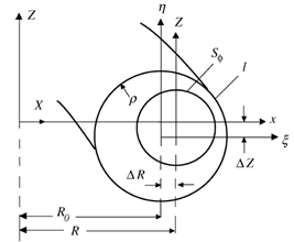
  is defined as (see the Table (2) and Fig.(1)):
 | (4) |
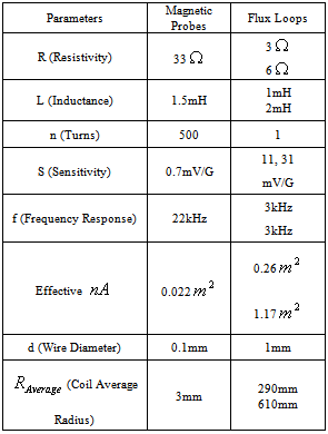
Table (2). Design parameters of the poloidal flux loops and magnetic probes
 |
| |
|
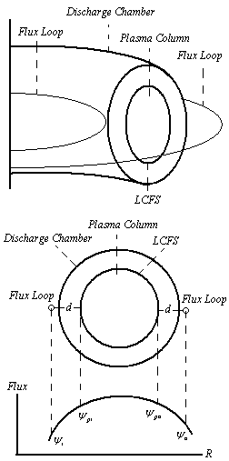 | Figure (1). Schematic diagrams of the two flux loops on outer surface of IR-T1 tokamak |
On the other hand, because of dependence of the plasma current distribution and poloidal beta to the magnetic fields distribution, therefore, measurements of magnetic fields around the plasma give us information about the Shafranov parameter. Magnetic fields distributions around the plasma are[1]: | (5) |
 | (6) |
where we used the quasi-cylindrical coordinates ( ), and
  is the displacement of the plasma column center. Eq.(5) and Eq.(6) are accurate for the low beta and circular cross section tokamak as IR-T1. By rearranging these relations a current independent relation for the plasma asymmetry factor obtained:
 | (7) |
where  and
and  are defined as:
 | (8) |
These values can be measured using local magnetic probes which positioned at above polar angles (see the Table (2) and Fig.(2)).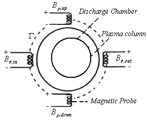 | Figure (2). Positions of the four magnetic probes on the outer surface of the IR-T1 tokamak chamber |
3. Multipole Moments Method for the Measurement of Plasma Column Displacement
The signals of magnetic probes which located along some closed contour around the minor cross sectional area of toroidal plasma can be weighted with certain factors with respect to each other to yield various spatial moments averaged over the current density in the plasma. An m-th multipole moment  in cylindrical coordinates
  in term of total current is given by[2,3]:
 | (9) |
where  is the plasma current,
  is the toroidal current density,
  and
and  are two given functions of
  (see the Fig.(3)).
  and
and  are the tangential and normal components of the magnetic field outside the plasma on the contour
  surrounding
  .
. | Figure (3). Geometry used for the multipole moments method |
In a large aspect-ratio tokamak, plasma position can be obtained from the first moment  :
: | (10) |
where ,
, 
 ,
, 
 motion:
 motion:
  The tangential and radial components of the magnetic field along a circular contour are:
 | (11) |
Using Eqs. (10) and (11): | (12) |
where:


 | (13) |
Since for a small displacement in a circular plasma  ,
,  is given by:
 | (14) |
Two coils were built according to Eq.(14) (see the Fig.(4))[3]: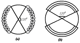 | Figure (4). Schematic diagram of the (a) Cosine coil and (b) Saddle Sine coils in IR-T1 Tokamak |
(a). The high order Cosine coil has the following number of turns: | (15) |
The coil signal is: | (16) |
(b). the Saddle Sine coil is of width: | (17) |
The coil signal is: | (18) |
Because of the technical difficulties in construction of the last coil (Eq.(17)) following approximation has been made:The Saddle Sine coil is of width: | (19) |
where  ,
, 

4. Analytical Solution of Equilibrium Problem or Grad-Shafranov Equation
For axially symmetric configurations as tokamaks, Maxwell's equations together with the force balance equation from Magneto Hydro Dynamics (MHD) equations, for stationary and ideally conducting plasmas, reduce to the two-dimensional, nonlinear, elliptic partial differential equation, or Grad-Shafranov equation (GSE): | (20) |
where
 | (21) |
and  , and
, and  are two free functions.In the IR-T1 tokamak which is the ohmically heated tokamak, expansion the Grad-Shafranov equation is solved by formally expanding as follows[4]:
  | (22) |
where  is the vacuum toroidal field at
  and
and  is a new free function replacing
  .In the first order solution or toroidal force balance approximation and if plasma was surrounded by a perfectly conducting shell located at r=b, then we have:
 | (23) |
If there are external coils to produce vertical magnetic field, the boundary condition on the flux function is modified so that we have:  | (24) |
where  is the flux function due to external vertical field coil and therefore the full toroidal correction to
  is:
is: | (25) |
The shift of the plasma column center from the geometrical center of vacuum chamber is given by:  | (26) |
where  Therefore we can write:
 | (27) |
where  is the poloidal beta,
  is the internal inductance of the plasma, and
  is the average vertical magnetic field over the vacuum chamber. We can find
  from Saddle Sine coil and combination of
  from magnetic probes measurement[5,6]:
 | (28) |
We measured these local magnetic fields with magnetic probes at above polar angles. Experimental results present in section 6.
5. Design and Fabrication of the Modified Rogowski and Saddle Sine Coils, Flux Loops, and Magnetic Probes
Turns density of the Cosine coil is  , area of the cross section of the Cosine coil is
  , radius of the Cosine coil ring is
  , with the integrator time constant of
  , and the sensitivity of Cosine coil is (see the Fig.(4)):
 | (29) |
Also in the IR-T1 tokamak two poloidal flux loops designed and installed on outer surface of vacuum chamber in polar angles  and
and  , with radiuses
  and
and  (see the Fig.(1) and Table (2)). The excessive fields are a fraction of the poloidal flux which passing through the flux loops, therefore essentially compensation is needed. Compensation is done with dry runs technique. Experimental result for the measurement of plasma position using this method will be presented in next section. Also in the IR-T1 tokamak four magnetic probes were designed and installed, two magnetic probes were located on the circular contour
  of the radius
  in angles of
  and
and  to detect the tangential component of the magnetic field and two magnetic probes are also located above,
  , and below,
  , to detect the radial component of the magnetic field
  (see the Fig.(2) and Table (2)). In this method, compensation is done with dry runs technique. Then, after integrating the compensated signals magnetic fields determined. By using a poloidal and normal components of the magnetic field which measured by four magnetic pickup coils, the Shafranov parameter was determined. The electric circuit used for the measurement of the
  signal that is supplied by the flux loops, magnetic probes, and modified Rogowski and Saddle Sine coils is showed in the Fig.(5):
 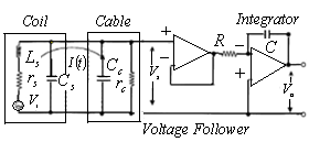 | Figure (5). Block diagram of the electric circuit used for the multipole moments method, flux loops, and magnetic probes |
In the diagram,  is the current in the coil circuit and
  is the coaxial cable output signal. The application of Kirchhoff’s law for this circuit yields the following equation:
 | (30) |
where  is the probe resistance,
  is the cable resistance and
  probe self-inductance. This expression is valid if the frequency of the interest signal
  is much smaller than the natural oscillation frequency of the coil (resonant frequency)
  . In this case, and since
  is smaller than
  , the capacitive reactance
  is greater than the inductive reactance,
  , such that for practical reasons the sum of the capacitances,
  , can be neglected. These conditions are satisfied in the measurement systems composed of our diagnostics tools.From the circuit of Fig.(5) we have:
 | (31) |
where  is the integrator time constant and
  is the inductive voltage supplied by each one of the diagnostics tools, which were placed around the IR-T1 tokamak vacuum chamber. According to Fig.(4-a) for induced voltage From Faraday’s law for Cosine coil with variable winding as
  , we can write:
  | (32) |
After integrating we have: | (33) |
where  is the turn per length and
  is the cross section of cosine coil,
  is the radius of Cosine coil ring and
  is the integrator output. Also for the Saddle Sine coil shown in Fig.(4-b) with variable width as
  ,
,  the integrator output can be obtained:
  | (34) |
where  and
and  are the constants which depends on cable and coils resistance and time constant of integrator.
6. Experimental Results and Comparison between Them
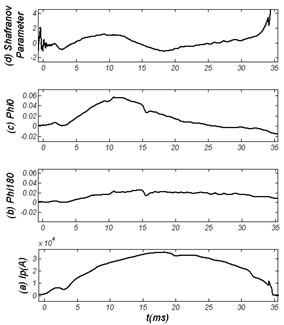 | Figure (6). Time evolution of (a) Plasma current, (b) Magnetic flux passing through loop which located at angle 180, (c) Magnetic flux passing through loop which located at angle 0, and (d) Shafranov parameter measured by the Flux Loops method |
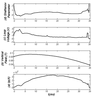 | Figure (7). Time evolution of (a) Plasma current, (b) Vertical magnetic field (c) Loop voltage, and (d) Shafranov parameter along the plasma current measured by the magnetic probes method |
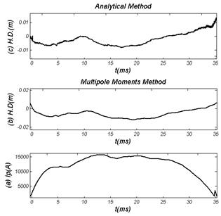 | Figure (8). Time evolution of (a) plasma current, (b) Horizontal Displacement (H.D.) obtained by the Multipole Moments Method, and (c) Horizontal Displacement (H.D.) obtained by the Analytical method |
We used the Eqs. (3) and (7) for the determination of Shafranov parameter and the Eqs. (14) and (27) for the determination of plasma column displacement in IR-T1 tokamak. Their results presented in Figs.(6-8). Moreover we plotted the magnetic flux surfaces for the plasma parameters at t=10ms in target shot on IR-T1 tokamak, as we expected there is a displacement of plasma column center as shown in Fig.(9). | Figure (9). Magnetic flux surfaces: Inward displacement of plasma column center is observable at t=10ms in target shot on IR-T1 tokamak |
7. Summary and Conclusions
We presented two comparative methods for the measurement of Shafranov parameter and also two comparative method for the measurement of plasma column displacement in IR-T1 tokamak: a poloidal flux loops and magnetic probes methods for the first purpose, and a multipole moments method and a method based on the analytical solution of equilibrium problem orGrad-Shafranov equation for the second purpose. In order to measurement of the Shafranov parameter, two flux loops were designed and installed on outer surface of the IR-T1 tokamak chamber, and then a poloidal flux obtained from them. From this measurement and based on the calculated current independent relation the Shafranov parameter determined. To compare the result, four magnetic probes were designed and installed on outer surface of the IR-T1, and again based on another calculated current independent relation the value of Shafranov parameter independently was measured. Experimental results of these measurements compared. On the other hand, a modified Rogowski and Saddle Sine coils were designed, constructed, and installed on outer surface of IR-T1 tokamak chamber and then displacement of plasma column were measured from them. To compare the plasma position obtained using the multipole moments method, a method based on the analytical solution of Grad-Shafranov equation is also experimented on the IR-T1 tokamak. Results are in good agreement with each other. Acceptable discrepancies between all results are because of (1) difference between the measured magnetic flux using the flux loops and desired magnetic flux on LCFS, (2) possible error in the measurement of local magnetic fields using the magnetic probes, (3) limited number of measurements, (4) large aspect ratio approximation for the IR-T1 tokamak, (5) approximation in the design of Saddle Sine coil, (6) first order solution or toroidal force balance approximation in the analytical based method, and (7) possible error in the compensation of all excessive fields and noises in the used techniques.Nevertheless, because of the local and not global measurements using the magnetic probes against the flux loops, we think that the flux loops give us more reliable information about the Shafranov parameter, and also because of the local and not global measurements using the magnetic probes against the modified Rogowski and Saddle Sine coils, we think that the multipole moments method give us more reliable information about the plasma column displacement.
ACKNOWLEDGEMENTS
This work was supported by Shabestar-Branch, Islamic Azad University, Shabestar, Iran
References
| [1] | V. S. Mukhovatov and V. D. Shafranov, Nucl. Fusion 11, 605 (1971) |
| [2] | L.E. Zakharov, V.D. Shafranov, Sov. Phys. Tech. Phys. 18 (2) 151-156, (1973) |
| [3] | I.P. Shkarofsky, Phys. Fluids 25 (1), 89-96, (1982) |
| [4] | J. P. Freidberg, Ideal MHD (Clarendon, Oxford, 1987) |
| [5] | A. Salar Elahi et al., J. Fusion Energy 28 (4), (2009), DOI: 10.1007/s10894-009-9198-x |
| [6] | H. Niomiya and N. Suzuki, Japanese Journal of Applied Physics, Vol. 21, No.9, September, pp. 1323-1327, (1982) |
| [7] | M. Shimada, D. J. Campbell, V. Mukhovatov et al., Nucl. Fusion 47, S1 (2007) |
| [8] | C. V. Atanasiu et al., Phys. Plasmas 11, 3510 (2004) |
| [9] | G. S. Lee et al., Nucl. Fusion 41, 1515 (2001) |
| [10] | S. H. Seo, Phys. Plasmas 16, 032501 (2009) |
| [11] | S. G. Lee et al., Rev. Sci. Instrum. 79, 10F117 (2008) |
| [12] | A. J. H. Donne, Nucl. Fusion 47, S337–S384, (2007) |
| [13] | F. Najmabadi and the ARIES Team, Fusion Eng. Des. 65, 143 (2003) |
| [14] | C. V. Atanasiu et al., Proceedings of the 30th EPS Conference on Controlled Fusion and Plasma Physics, St. Petersburg, ECA vol. 27A, p-2 104, (2003) |
| [15] | M. Emami et al., J. Plasma Physics 76 (1), (2009), Doi: 10.1017/S0022377809008034 |
| [16] | J. Wesson, Tokamaks, (Clarendon, Oxford, 1997) |
| [17] | I. H. Hutchinson, Principles of Plasma Diagnostics, (Cambridge University Press, Cambridge, 1987) |
 Abstract
 Reference
 Full-Text PDF
 Full-text HTML