H. Mansour1, Hend M. Saad2, M. Aziz2
1Physics Department, Faculty of Science, Cairo University, Giza, Egypt
2Nuclear and Radiological Regulatory Authority, Ahmed Al Zomor St., Nasr City, Cairo, Egypt
Correspondence to: Hend M. Saad, Nuclear and Radiological Regulatory Authority, Ahmed Al Zomor St., Nasr City, Cairo, Egypt.
| Email: |  |
Copyright © 2012 Scientific & Academic Publishing. All Rights Reserved.
Abstract
Understanding of the time-dependent behavior of the neutron population in a nuclear reactor in response to either a planned or unplanned change in the reactor conditions is of great importance to the safe and reliable operation of the reactor. In the present work, the point kinetics equations are solved numerically using the stiffness confinement method (SCM). The solution is applied to the kinetic equation in the presence of different types of reactivities, and is compared with other method. This method is, also used to analyze reactivity induced accidents in two reactors. The first reactor is fueled by uranium and the second is fueled by plutonium. This analysis presents the effect of negative temperature feedback with the addition positive reactivity of the control rods to overcome the occurrence of the control rod ejection accident and damaging of the reactor. Both the power and the temperature pulse following the reactivity- initiated accidents are calculated. The results are compared with previous works and satisfactory agreement is found.
Keywords:
Reactivity Induced Accident, Stiffness Confinement Method, Point Kinetic Equations, Control Rods Ejection, Reactivity Coefficient, Safety Analysis
Cite this paper: H. Mansour, Hend M. Saad, M. Aziz, Analysis of Reactivity - Initiated Accident for Control Rods Ejection, Journal of Nuclear and Particle Physics, Vol. 3 No. 4, 2013, pp. 45-54. doi: 10.5923/j.jnpp.20130304.01.
1. Introduction
The reactivity- initiated accident is a nuclear reactor accident that involves inadvertent removal of a control element from an operating reactor, thereby causing a rapid power excursion in the nearby fuel elements and temperature. The postulated scenarios for reactivity initiated accidents are therefore focused on a few events, which result in exceptionally large reactivity excursions, and therefore are critical to fuel integrity. In reference[2] model, the reactivity- initiated accident is considered to be due to negative temperature feedback. In the present work, we consider the reactivity accident to be due to negative temperature feedback with the addition positive reactivity of the control rods to prevent such accidents of the control rods ejection and damaging of the reactor. We analyzed accidents in different types of reactors, e.g. modular high temperature gas cooled reactor design like HTR-M, and modular fast reactor design like PRISM, using the stiffness confinement method for solving the kinetics equations. The stiffness confinement method SCM is used to solve the kinetics equations, and overcome the stiffness problem in reactor kinetics[1]. The idea is based on the observation that the stiffness characteristic is present only in the time response of the prompt neutron density, but not in that of the delayed neutron precursors. The method is therefore devised to have the stiffness decoupled from the differential equation for precursors and is confined to the one for prompt neutrons, which can be solved[1]. Numerical examples of applying the method to a variety of problems are given. The method is also used to analyze the reactivity induced accidents in two reactors data, the modular high temperature gas cooled reactor (HTR-M) which is fueled by uranium, and modular fast reactor design (PRISM) which is fueled by plutonium. In the next sections, we discuss the mathematical method; present the results and discussion, and give the conclusion.
2. Mathematical Method
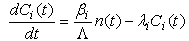
The stiffness confinement method is used to overcome the stiffness problem in reactor kinetics for solving the point kinetics equations. The idea is based on the observation, that the stiffness characteristic is present only in the response time of the prompt neutron density, but not in that of the delayed neutron precursors. The method is, therefore, devised to have the stiffness decoupled from the differential equations for the precursors and confine it to the one for the prompt neutrons, which can be analytically solved[1]. The point kinetics equations are a system of coupled ordinary differential equations, whose solution give the neutron density and delayed neutrons precursor concentrations in a tightly coupled reactor as a function of time. Typically, these equations are solved using the reactor model with at least six delayed precursor groups, resulting in a system consisting of seven coupled differential equations. Obtaining accurate results is often problematic, because the equations are stiff with many techniques, where very small time steps are used. These equations take the following form with an arbitrary reactivity function[3, 4]: | (1) |
 | (2) |
where: n(t) is the time-dependent neutron density, or (power or neutron flux) all units are (MW) as power unit; Ci(t) is the ith group delayed neutrons precursor concentration or delayed neutrons emitter population or precursor density (“latent-neutron” density or latent power; same units as in the power); i is the number of precursor group; ρ(t) is the time-dependent reactivity; βi is ith group delayed neutrons fraction, and β = Σi·βi , is the total delayed neutrons fraction. In addition, Λ is the neutron generation time (s), and λi is decay constant of the ith group delayed neutrons emitters (s-1).Introducing a set of “Reduced” precursor density functions Ĉi (t) and neutron density n (t), through the following equation[1]: | (3) |
Defining two auxiliary functions w (t) and u (t), as in Eqs. (4) and (5): | (4) |
The function w (t) is defined in Eq. (9) below and provides the key mechanism of the SCM. The function u (t), however, has nothing to do with stiffness decoupling and is not really required theoretically. Since an exponential behavior is often characteristic for the first, order differential equations, however, a proper choice of u (t) may make Ĉi (t) vary more slowly in time and thus expedite the numerical calculation. Choose the following u (t)[1]: | (5) |
Where, S (t) is defined by Eq. (7) as the sum over all λi·Ci (t). We can rewrite Eqs. (1) and (2) as follows[1]: | (6) |
 | (7) |
And,  Suppose that, it is always possible to express:
  | (8) |
and rewrite Eq. (1) as: | (9) |
Eqs. (6)- (9), form the complete set of kinetics equations for the SCM. The initial conditions are satisfied to be: | (10a) |
 | (10b) |
 | (10c) |
and, | (10d) |
By using the initial conditions, we can obtain the numerical solution of the equations. We first start by setting w and u in Eq. (6) at their initial values and solve Eq. (6) for Ĉi by discretizing the equation in t. Having obtained Ĉi, we calculate S (t) with Eq. (7). Then we use Eq. (4) to re-evaluate w(t), plug it back into Eq. (6) , and repeat the process until w converges (requiring 50 iterations). Calculation for the current time step is finished with an evaluation of the output value of w and u via Eqs.(4) and (5). Afterward, we predict the input values of w and u for the next time step by a linear extrapolation from their output values in the previous and current time steps, and repeat the whole process of calculation for the next time step. It should be emphasized that time step, there is iteration to convergence on w, but no iteration for the function u, because u is not required by the theory of the SCM, and is in principle, an arbitrary independent function chosen only to expedite the computation. A computer program is designed with programming language FORTRAN, and MATLAB code to solve the above equations numerically using Runge - Kutta method for the above differential equations and the output power and temperature are determined under different input reactivities. It is assumed that, the reactor has a negative temperature coefficient of reactivity α (α > 0), when a large step reactivity ρ0 (ρ0 >β) is inserted. Consider the temperature feedback, the real reactor reactivity is:[3, 4] | (11) |
Then, the derivative of Eq. (11) with respect to time (t) is: | (12) |
Where, T (t) and T0 are the reactor temperature, and initial temperature of the reactor, respectively. After the large reactivity ρ0 is inserted into the reactor, the power responds quickly and the adiabatic mode can be used for the calculation of reactor temperature.[3, 4]Then, the derivative of the temperature w.r.to time can be given as follows: | (13) |
Where, Kc is the reciprocal of thermal capacity of reactor. Substituting Eq. (12) into Eq. (13) results in the following: | (14) |
3. Numerical Solution
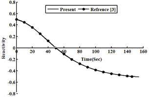
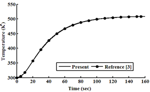
The numerical solution of the point kinetics equations is based on SCM .The results are compared against other result, which obtained with other method. The other method is highly accurate, but there are vary widely in there complexity of implementation[1].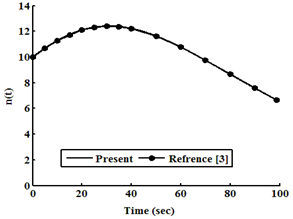 | Figure 1. Neutron density as a function of time at ρ0=0.2β |
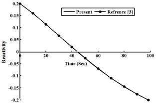 | Figure 2. Reactivity as a function of time at ρ0=0.2β |
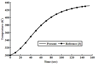
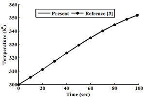 | Figure 3. Temperature as a function of time at ρ0=0.2β |
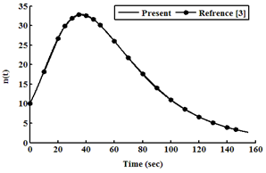 | Figure 4. Neutron density as a function of time at ρ0=0.5β |
 | Figure 5. Reactivity as a function of time at ρ0=0.5β |
 | Figure 6. Temperature as a function of time at ρ0=0.5β |
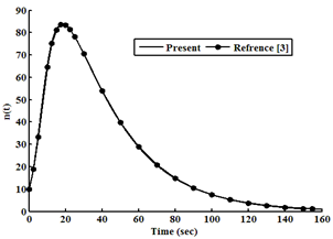 | Figure 7. Neutron density as a function of time at ρ0=0.8β |
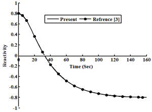 | Figure 8. Reactivity as a function of time at ρ0=0.8β |
 | Figure 9. Temperature as a function of time at ρ0=0.8β |
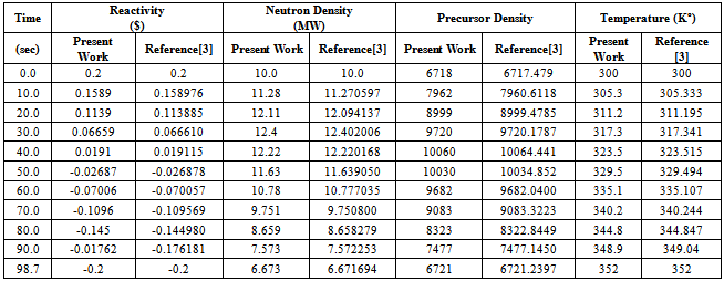
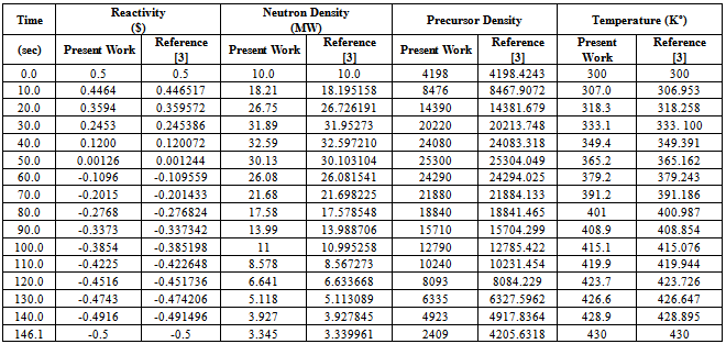
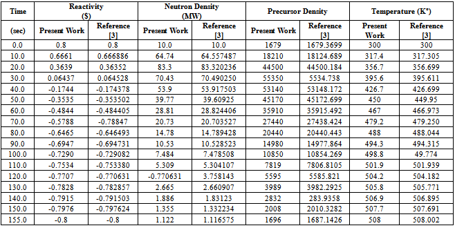
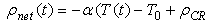
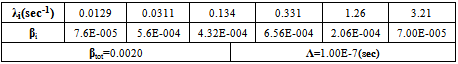
Considering an example 235U as a fissile material under large step reactivity, taking three initial reactivities inserted into the reactor. It is assumed that, the input parameters are: λi(s-1) = (0.0127, 0.0317, 0.155, 0.311, 1.4, 3.87), βi= (0.000266, 0.001491, 0.001316, 0.002849, 0.000896, 0.000182), Λ=0.0001(s), βtot= 0.0065, Kc= 0.05 K/ (MW s), and α =5×10⁻⁵ (K−1). In this case, ρ0 =0.2β and 0.5β and 0.8β for t ≥ 0 are used into the reactor, which is operating in critical state with initial power 10 (MW). The relation between time, reactivity, neutron density, and temperature using the numerical solution by the SCM, which are compared with the work of[3], is presented in tables (1, 2, and 3). The results indicate that the present model solutions are in good agreement with other works as shown in following figures (1-8). The iteration in computing is used for repeating the process until w and u converge (requiring approximately 100 iterations) to get step reactivity insertion with accurate results which are compared with other calculations[1, 3].Table 1. Neutron Density, Precursor Density, Reactivity and Temperature are functions of time at initial reactivity 0.2β solved with SCM
 |
| |
|
Table 2. Neutron Density, Precursor Density, Reactivity and Temperature are functions of time at initial reactivity 0.5β
 |
| |
|
Table 3. Neutron Density, Precursor Density, Reactivity and Temperature are functions of time at initial reactivity 0.8β
 |
| |
|
4. Analysis of Reactivity- Initiated –Accident
4.1. Reactivity- Initiated Accident
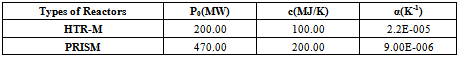
Reactivity- initiated accident involves an unwanted increase in fission rate and reactor power. The power increase may damage the reactor core, and in very severe cases, even lead to the disruption of the reactor. The immediate consequence of reactivity- initiated accident is a fast rise in fuel power and temperature. The power excursion may lead to failure of the nuclear fuel rods and release of radioactive material into primary reactor coolant. In this study, a new computer program has been developed for simulating the reactor dynamic behavior during reactivity induced transients, and it has been used for the analysis of specified reactivity - initiated accidents in several cases. We introduce the two model reactors with system parameters that are characteristic for modular high temperature gas-cooled reactor design like HTR-M[6], and modular fast reactor design like PRISM[7]. For simplicity, we refer to the input dates of two reactors (HTR-M and PRISM) in tables (4, 5, and 6). For the delayed neutron parameters, it is assumed that, HTR-M is fuelled by 235U and PRISM by 239Pu as fissile nuclides. The dynamic equations (15:21) for the two models are the conventional point reactor kinetic equations in combination with a linear temperature feedback for the reactivity, an adiabatic heating of the core after loss of cooling[2], where Eq. (17 a) may be modified to add positive control rods reactivity as: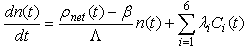 | (15) |
 | (16) |
 | (17) |
 | (19) |
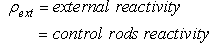
 | (20) |
Where, n (t) = reactor power (MW), ρnet (t) = is the time-dependent reactivity function, ρCR= Addition positive reactivity of the control rods, β = total delayed neutron fraction, β=Σiβi. βi= Delayed neutrons faction of ith group. Λ = neutron generation time (sec), λi = decay constant of ith group delayed neutrons emitters (sec)-1, Ci (t) =delayed neutrons emitter population (in power units), α = temperature coefficient of reactivity (K-1).In the equation of total reactivity ρnet (t), the additional positive reactivity of the control rods ρCR has four cases to prevent the control rods ejection accident as:The input parameters of the kinetic equations of two reactors with different fissile materials are shown in tables 4: 6.Table 4. 235U (Thermal Neutrons)
 |
| |
|
Table 5. 239PU (Fast Neutrons)
 |
| |
|
Table 6. Adiabatic Inherent Shutdown Data for Two Model Reactors
 |
| |
|
4.2. Reactivity Evaluation
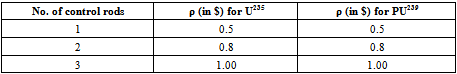
The reactivity of one, two and three control rods worth are calculated based on the assumptions of relating the control rod worth by the delayed neutron fraction β. We assumed that, the ejection of one, two and three rods could induce positive reactivity as indicated in Table 7 for each type of reactors, in the two models.Table 7. Additional Positive Reactivity of Control Rods Insertion
 |
| |
|
5. Results and Discussion
5.1. First Reactor (PRISM Reactor)
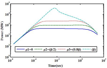
PRISM Reactor is assumed to be critical at the zero power condition, and the limited value of time (sec) on x axis is 300 (sec). Reactivity is also added step by step. The control rod insertion increases the thermalization of neutrons, results in a positive reactivity addition. Control rod insertion requires a certain driving force. The driving forces on the control rods in the reactors are the buoyancy from the fuel material and the supporting force from the control system of the reactor. If the control system should lose the support of control rods or control rods should break, control rods would be flown out of the reactor. Thus, in PRISM reactor, accidental insertions can result from the ejection of control rod drive, and/or control rod control system or operator error. Power transients are shown in Figures (10, 11) for one and two, and three control rod ejections, respectively. As can be seen, three rods are ejected; a large power pulse is generated about 83.8085 times of the initial value of power in a very short time. This is because; the accident is reactivity accident. However, the fuel temperature is stabilized at approximately 1435 (K) at the maximum as shown in Figure 12. Even, three control rods are inserted; the maximum temperature is not exceeding 1502 (K) as shown in Figure 12. 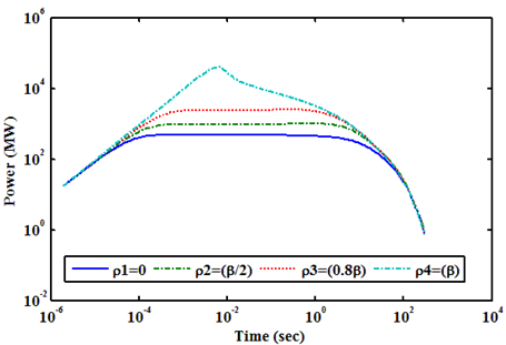 | Figure 10. Shows Power (MW) Transient at Zero Power Condition with Different Values of Positive Reactivity of Control Rods Ejection for PRISM Reactor |
 | Figure 11. Shows Power (MW) Transient at Full up to 30s with Different Values of Positive Reactivity of Control Rods Ejection for PRISM Reactor |
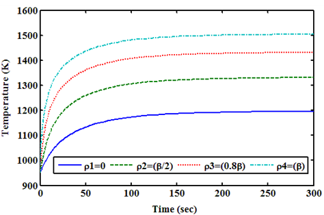 | Figure 12. Shows Temperature (K) During the Transients at Zero Power for PRISM Reactor |
5.2. Second Reactor (HTR-M Reactor)
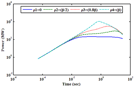
HTR-M Reactor is assumed to be critical at the zero power condition, and the limited value of time (sec) on x axis is 300 (sec). Reactivity is also added step by step as explained above in PRISM reactor. The Power transients for one, two, and three control rods ejection are shown in Figures (13, 14), respectively. As can be seen, three rods are ejected; a large power pulse is generated about 53.45 times from the initial value of power in very short time. This is because; the accident is reactivity accident. However, the fuel temperature is stabilized at approximately 916.8 (K) at the maximum as shown in Figure 15. Even, three control rods are inserted; the maximum temperature is not exceeding 983.1 (K) as shown in Figure 15.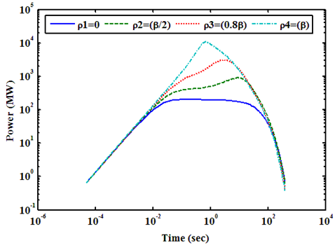 | Figure 13. Shows Power (MW) Transient at Zero Power Condition with Different Values of Positive Reactivity of Control Rods Ejection for HTR-M Reactor |
 | Figure 14. Shows Power (MW) Transient at Zero Power Condition up to 30s with Different Values of Positive Reactivity of Control Rods Ejection for HTR-M Reactor |
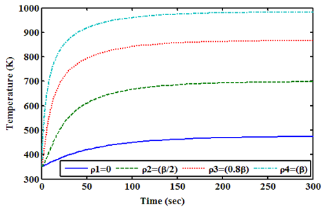 | Figure 15. Shows Temperature (K) During the Transients at Zero Power for HTR-M Reactor |
6. Conclusions
A computer program is designed to solve the point reactor dynamics equations using the stiffness confinement method (SCM) and different input reactivity. The resultant powers are determined and illustrated. Good accuracy in comparison with reference values is obtained. The model is applied to two types of reactors. There are modular of fast reactor design like PRISM reactor[7], and modular high temperature gas-cooled reactor design like HTR-M reactor[6]. The PRISM reactor is fuelled by 239Pu, the HTR-M reactor is fuelled by 235U as fissile nuclides. In the work of Van Dam[2], (we used it for comparison purpose), the author obtained reactivity accident due to negative temperature feedback after loss of cooling to different reactors with different fissile material. The reactivity- initiated accident is considered to be due to a linear temperature feedback, and an adiabatic heating of the core after loss of cooling. In the present work, we consider reactivity accident due to a linear temperature feedback, an adiabatic heating of the core after loss of cooling with the addition positive reactivity of the control rods. We analyzed accidents in different types of reactors (HTR-M and PRISM), using the stiffness confinement method for solving the kinetic equations. In the present work, one obtains reactivity induced accident due to control rods ejection of (negative temperature feedback, and addition positive reactivity of the control rods) to overcome the occurrence of the control rods ejection accident, and prevent reactors from damage. The addition positive reactivity of the control rods has four cases: (0, β/2, 0.8β, β), where at the zero case only negative temperature feedback as the case of[2], and the other cases negative temperature feedback with the addition positive reactivity of control rods, this is called reactivity - initiated accident. For 239Pu fueled reactor, when reactivity of the reactor is increased by β, the reactor peak power increases by 83.8085 times of the initial value with saturated temperature of 1,503 (K). For HTR-M reactor, power increases by a factor of 53.5 times the initial value at equilibrium temperature of 1,000 (K) when the reactivity is increased by β.
References
| [1] | Y. Chao, Al. Attard, A resolution to the stiffness problem of reactor kinetics, Nuclear Science and Engineering 90 (1985) 40-46. |
| [2] | H.Vandam, Dynamics of passive reactor shutdown, Prog.Nucl.Energy, 30, (1996), 255. |
| [3] | A. A. Nahla, E. M. E. Zayed,”Solution of the nonlinear point nuclear reactor kinetics equations”, Prog. Nucl. Energy, P. (1-4), (2010). |
| [4] | J.J. Duderstadt, L.J, L.J, L.J. Hamilton, Nuclear Reactor Analysis. John Wiley & Sons, 1976, pp. 233-251. |
| [5] | D. McMahon, A. Pierson, A Taylor series solution of the reactor point kinetics equations, arXiv: 1001.4100, V2 (2010) 1-13. |
| [6] | K. Kugeler, R. Schulten, High Temperature Reactor Technology, Springer, Berlin, 1989, pp. 246-260. |
| [7] | G.J. Van Tuyle, G.C. Slovik, R.J. Kennett, B.C. Chan, A.L. Aronson, Analyses of unscramed events postulated for the PRISM design, Nucl. Technol.91 (1990) 165-184. |
 Abstract
 Reference
 Full-Text PDF
 Full-text HTML