-
Paper Information
- Next Paper
- Paper Submission
-
Journal Information
- About This Journal
- Editorial Board
- Current Issue
- Archive
- Author Guidelines
- Contact Us
Journal of Nuclear and Particle Physics
p-ISSN: 2167-6895 e-ISSN: 2167-6909
2013; 3(1): 1-7
doi:10.5923/j.jnpp.20130301.01
Determination of Plasma Parameters as well as Electrons Distribution Function
 Abstract
 Reference
 Full-Text PDF
 Full-text HTML
Alireza Paknezhad1, Ahmad Salar Elahi2, M. Ghoranneviss2, R. Arvin2, S. Mohammadi2
1Physics Department, Shabestar Branch-Islamic Azad University, Shabestar, Iran
2Plasma Physics Research Center, Science and Research Branch, Islamic Azad University, Tehran, Iran
Correspondence to: Alireza Paknezhad, Physics Department, Shabestar Branch-Islamic Azad University, Shabestar, Iran.
| Email: |  |
Copyright © 2012 Scientific & Academic Publishing. All Rights Reserved.
In this research we determined the biasing effects on the plasma electrons distribution function and plasma displacement in a low beta, large aspect ratio and circular cross section tokamak. For this purpose, a movable biasing system was designed, constructed, and installed, and then the positive voltage applied to an electrode inserted inside the tokamak limiter and the plasma current, particle distribution function and also the plasma horizontal displacement in the absence and presence of the biasing based on the multipole moments technique were measured. Measurements result has shown a modification of plasma confinement by decreasing the plasma displacement.
Keywords: Tokamak, Biasing, Particles Distribution Function, Plasma Displacement
Cite this paper: Alireza Paknezhad, Ahmad Salar Elahi, M. Ghoranneviss, R. Arvin, S. Mohammadi, Determination of Plasma Parameters as well as Electrons Distribution Function, Journal of Nuclear and Particle Physics, Vol. 3 No. 1, 2013, pp. 1-7. doi: 10.5923/j.jnpp.20130301.01.
Article Outline
1. Introduction
- Biasing experiments on the tokamaks have been very successful in improving the both plasma energy and particle confinement by setting up a radial electric field at the plasma edge. It is accepted that improvement of plasma confinement can be induced in tokamaks by electrically biased electrodes which inserted in the plasma edge region. The biased electrode produces a radial current between itself and the vacuum vessel and the resulting force originates sheared flows, which have a suppressing effect on turbulence and related transport. Plasma turbulence is one of the main causes of anomalous transport in toroidal magnetic confinement devices. Edge biasing experiments have been found to be important in modifying edge turbulence and transport, but the mechanism of biasing penetration in edge fluctuations and its levels are different with respect to devices operation. A velocity shear stabilization mechanism has been proposed to be responsible for an improvement in plasma confinement. A clear correlation between the modifications of radial electric fields induced by bias and the reduction of turbulence has been also observed in several experiments[1-4]. The control of the shear layer is therefore an important tool to modify transport in tokamaks[5-10]. Electrode biasing has been used on IR-T1 tokamak to investigate the possibility of modifying the plasma confinement. It has been shown that both positive limiter and electrode bias can modify the plasma behavior. Electrode bias is more efficient than limiter bias in modifying the radial electric field and confinement, introducing stronger modification in the plasma potential, probably because it was inserted a few cm inside the last closed flux surface. However, it has been also shown that for negative electrode and limiter bias no significant modification of either the global or the edge plasma parameters was observed since the electrode (limiter) drawn current was too low to modify the plasma parameters. In order to obtain the larger current necessary to modify confinement at negative applied voltages, biasing experiments have been performed using the horizontal electrode inserted well inside the fully poloidal limiter position[11-56]. In this research, biasing experiments using the horizontal electrode are presented; emphasizing the influence of the biased electrode on the electrons distribution function and plasma horizontal displacement measured using the multipole moments method. Design, construction and experimental set-up of the electrode biasing system on IR-T1 will be presented in section 2. Theoretical approach for the measurement of plasma displacement using the multipole moments method in presence of the biased electrode and experimental results will be presented in section 3. Summary and conclusion will be discussed in section 4.
2. Design, Construction, and Experimental Set-up of the Biasing System
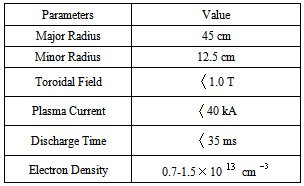
- IR-T1 is a low beta, large aspect ratio, and circular cross-section tokamak (see Table (1)), which has two stainless steel grounded fully poloidal limiters with radiuses of 12.5cm. In the experiments described the biased electrode position has been varied between 11.5-12.5cm, and the bias applied between the electrode and the vessel. The main diagnostics used in this work are a poloidally and radially oriented magnetic probes, a poloidal flux loop, and a diamagnetic loop. The experiments were performed in hydrogen. An average plasma density was in the range
 the toroidal magnetic field induction
  , the plasma current
  .Measurement of the plasma displacement was performed using a two flux loops (see the next section). The electrode consists of a stainless steel circular head, 2 mm in radial direction (width) and 2 cm in poloidal direction (diameter). It is inserted approximately 1 cm past the fixed poloidal limiter into the plasma through the low field side of the tokamak. A capacitor bank biases the electrode positive or negative with respect to the grounded wall. The applied electrode voltage
  is in the range −400 to +400 Volt, and the bias current
  is in the range -40 to +40 Ampere. Biasing experiments were performed in regime with ohmic heating.
|
3. Theoretical Approach for the Measurement of Plasma Displacement Using the Multipole Moments Technique and Experimental Results
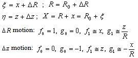
- An m-th multipole moment
 in cylindrical coordinates
  in term of total current is given by[16, 17]:
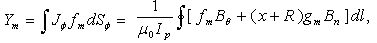 | (1) |
 is the plasma current,
  is the toroidal current density,
  and
and  are two given functions of
  (see the Fig. (1)).
  and
and  are the tangential and normal components of the magnetic field outside the plasma on the contour
  surrounding
  In a large aspect-ratio tokamak, plasma position can be obtained from the first moment
  [17]:
[17]: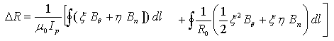 | (2) |
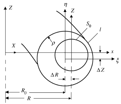 | Figure (1). Geometry used for the multipole moments method |
 | (3) |
 | (4) |
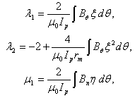
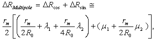
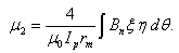 Since for a small displacement in a circular plasma
 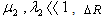 is given by:
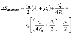 | (5) |
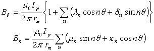
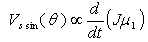
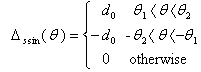
 terms can be determined using a modified Rogowski and Saddle coils. The two coils were built according to Eq. (4)[18] (see the Fig. (2)):
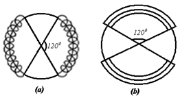 | Figure (2). Schematic diagram of the Cosine and Saddle sine coils in IR-T1 Tokamak |
 | (6) |
 | (7) |
 | (8) |
 | (9) |
 | (10) |
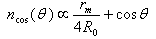
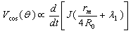
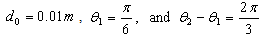 Turns density of the cosine coil is,
  , area of the cross section of the cosine coil,
  , radius of the cosine coil ring,
  , with the integrator time constant of
  , and the sensitivity of cosine coil,
  . In this research we reported mainly the effects of the electrode biased with positive voltage on the plasma displacement. Alternating bias voltages (50-200 Hz, 400 peak voltage) provided by a transformer have been used to determine the electrode voltage-current characteristic in a single shot. This is illustrated in the Figure (3), which shows the variation of the electrode current and voltage for 1cm inserted electrode. Positive bias has been applied to the electrode at t=12.5ms during 14.5ms.
 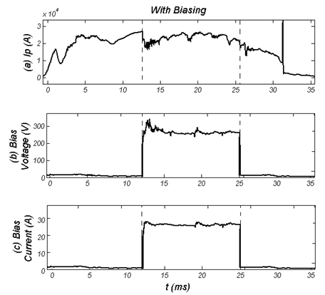 | Figure (3). (a) Time evolution of the plasma current in presence of the biasing, (b) time evolution of the bias voltage, and (c) time evolution of the bias current |
 . Figure (8), (a) Time evolution of the plasma current in absence of the biasing, (b) time evolution of the plasma Horizontal Displacement (H.D.) in absence of the biasing, (c) the plasma current in presence of the positive biased electrode between 12.5ms-27ms, and (d) time evolution of the of the plasma Horizontal Displacement (H.D.) in presence of the positive biasing between 12.5ms-27ms. As observable, the plasma displacement is decreased. It is because of that, positive bias increases significantly the magnitude of the radial electric field in the region inside the fixed limiters. Also, one of the results of improvement of plasma confinement is the plasma displacement which is decreased.
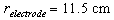
 | Figure (4). Electrons Distribution Function at t=32-33 ms |
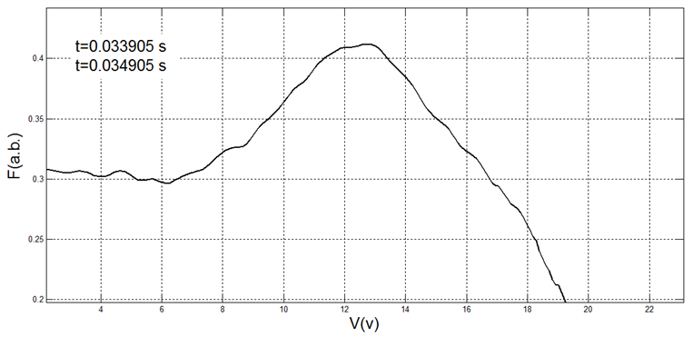 | Figure (5). Electrons Distribution Function at t=33-34 ms |
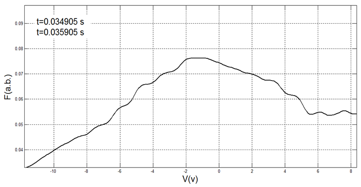 | Figure (6). Electrons Distribution Function at t=34-35 ms |
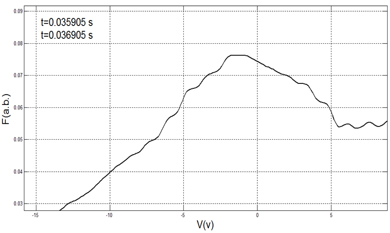 | Figure (7). Electrons Distribution Function at t=35-36 ms |
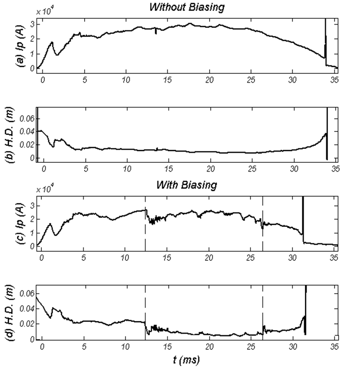 | Figure (8). (a) Time evolution of the plasma current in absence of the biasing, (b) time evolution of the plasma Horizontal Displacement (H.D.) in absence of the biasing, (c) the plasma current in presence of the positive biased electrode between 12.5ms-27ms, and (d) time evolution of the of the plasma Horizontal Displacement (H.D.) in presence of the positive biasing between 12.5ms-27ms |
4. Summary and Conclusions
- In this research we determined the biasing effects on the plasma particles distribution function and plasma displacement in a low beta, large aspect ratio and circular cross section tokamak. For this purpose, a movable biasing system was designed, constructed, and installed on the IR-T1, and then the positive voltage applied to an electrode inserted inside the tokamak limiter and the plasma current, electrons distribution function and also the plasma horizontal displacement in the absence and presence of the biased electrode based on the multipole moments technique were measured. Measurements result has shown a modification of plasma confinement by decreasing the plasma displacement.
ACKNOWLEDGEMENTS
- This work was supported by Shabestar-Branch, Islamic Azad university under contract No.51953910226001.