A. Salar Elahi, M. Ghoranneviss
Plasma Physics Research Center, Science and Research Branch, Islamic Azad University, Tehran, Iran
Correspondence to: A. Salar Elahi, Plasma Physics Research Center, Science and Research Branch, Islamic Azad University, Tehran, Iran.
| Email: |  |
Copyright © 2012 Scientific & Academic Publishing. All Rights Reserved.
Abstract
In this paper we presented comparative estimations of plasma horizontal displacement in the IR-T1 tokamak. In the first method, two poloidal flux loops were designed and installed on outer surface of the IR-T1 tokamak chamber, and then the plasma displacement is obtained from them. To compare the result obtained using this method, analytical solution of the Grad-Shafranov equation is also experimented on the IR-T1. Results of the two methods are in good agreement with each other.
Keywords:
Tokamak, Shafranov Shift, Poloidal Flux Loop, Grad-Shafranov Equation
Cite this paper:
A. Salar Elahi, M. Ghoranneviss, "Estimation of Plasma Horizontal Displacement using Flux Loops and Comparison with Analytical Solution in IR-T1 Tokamak", Journal of Nuclear and Particle Physics, Vol. 2 No. 6, 2012, pp. 142-146. doi: 10.5923/j.jnpp.20120206.02.
1. Introduction
In ohmically heated tokamaks (low Beta tokamaks), radial pressure balance is achieved by the poloidal field, and toroidal force balance is achieved by equality between the external vertical field force (Lorentz force) and outward forces due to toroidal configuration. But, in toroidal force balance problem, the two opposite forces may be not equal and therefore plasma intend to shift inward or outward, which it is dangerous for tokamak plasma. Therefore, plasma equilibrium study is one of the fundamental problems of the magnetically confined plasmas. There are many available experimental methods and analytical solutions of the steady state magnetohydrodynamics (MHD) equations, in particular, the Grad-Shafranov equation for the plasma equilibrium problem. Control of plasma position plays an important role in plasma confinement and the achievement of optimized tokamak plasma operation. Determination of accurate plasma position during confinement time is essential to transport it to a control system based on feedback. Over the years different methods have been developed to analysis the tokamak plasma equilibrium problems .In this paper we present two experimental and analytical methods for determination of plasma column center in IR-T1, which is a small, air core, low
 and large aspect ratio tokamak with a circular cross section (see Table 1). Details of the poloidal flux loops technique for measurement of the plasma displacement will be presented in section 2. Analytical solution of the Grad-Shafranov equation will be presented in section 3. Experimental results and comparative between them also will be presented in section 4. Also summary and conclusion will be presented in section 5.
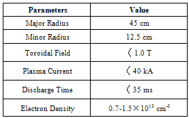
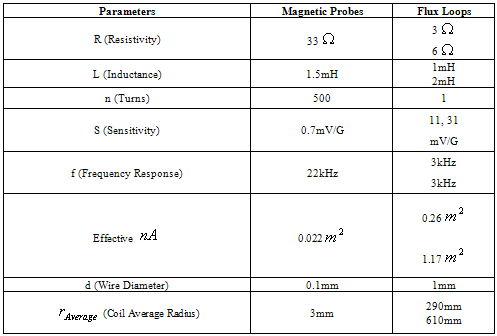
 Table 1. Parameters of the IR-T1 tokamak
 |
| |
|
2. Poloidal Flux Loops Method in Measurement of Plasma Position
Poloidal flux loop is a simple toroidally loop which measures the poloidal magnetic flux and an array of loops are usually used in control and reconstruction of plasma equilibrium states. The magnetic flux passing through such a loop is equal to  , where
  represents magnetic poloidal flux. In the ohmically heated tokamaks, ohmic coils field is the main fraction of poloidal flux which passing through the flux loop. Therefore to obtain net poloidal flux due to plasma, compensation is required for all excessive flux. Because of large area of the flux loop, the inductive voltage is also large and then it consists of usually one turn. According to relation for frequency response, it is obvious that because of small self-inductance, frequency response of flux loop usually is higher than which desired. As we know magnetic probe is suitable for measurement of plasma position only in circular cross section plasma and not for elongated one, but the flux loop can be used in both elongated and circular section tokamaks. Therefore we used these two techniques for the IR-T1 tokamak with circular cross section. The plasma boundary is usually defined by Last Closed Flux Surface (LCFS). At the LCFS poloidal magnetic flux is constant, if we install some flux loops at some distance in vicinity of LCFS, then we can find plasma displacement from the difference in poloidal fluxes that received with flux loops according to Shafranov equation. In the quasi-cylindrical coordinates
  for the poloidal magnetic flux we have
 .
. | (1) |
and where 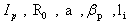 are the plasma current, major and minor plasma radiuses, poloidal beta and internal inductance of the plasma. The relationship between poloidal magnetic flux and plasma displacement is:
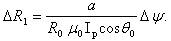 | (2) |
According to Figure 1 the poloidal flux is obtained: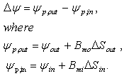 | (3) |
and where  are the poloidal flux which obtained with outer and inner flux loops respectively,
  and
and  are the average magnetic fields between outer and inner flux loops and the plasma surface respectively which can be obtained from magnetic probes,
  is the intervening area for each loop defined as:
  , where d is the distance between LCFS and each loop and
  is the distance between the midpoint (d/2) and center of the device (see Fig. 1). In the IR-T1 tokamak two poloidal flux loops were designed and installed on outer surface of vacuum chamber in polar angles
  and
and  , with radiuses
  and
and  (see Figure 1 and Table (2)).
 Table 2. Design parameters of the poloidal flux loops and magnetic probes
 |
| |
|
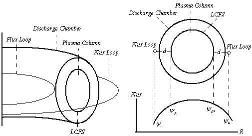 | Figure 1. Schematic diagrams for positions of the two flux loops on outer surface of the IR-T1 tokamak |
As mentioned above, the ohmic field is the significant fraction of the poloidal flux which passing through the flux loop, therefore essentially compensation is needed. Compensation is done with all fields discharge without plasma and subtraction them from the total flux that received with flux loop. Experimental result for measurement of plasma position using this method will be presented in section 4.
3. Analytical Solution of the Grad-Shafranov Equation
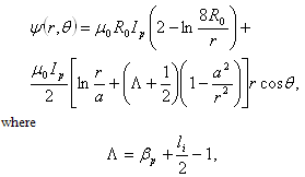
For axially symmetric configurations, Maxwell's equations together with the force balance equation from MHD equations, for stationary and ideally conducting plasmas, reduce to the two-dimensional, nonlinear, elliptic partial differential equation, or Grad-Shafranov equation (GSE)  :
: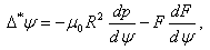 | (4) |
where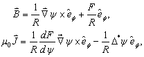 | (5) |
and  , and
, and  are two free functions.In the IR-T1 tokamak which is the ohmically heated tokamak, the Grad-Shafranov equation is solved by formally expanding as follows
 :
: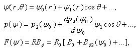 | (6) |
where  is the vacuum toroidal field at,
 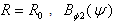 is a new free function replacing
  .In the first order solution or toroidal force balance approximation and if plasma is surrounded by a perfectly conducting shell located at r=b, then we have:
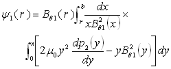 | (7) |
If there are external coils to produce vertical magnetic field, the boundary condition on the flux function is modified so that we have:  | (8) |
where  is the flux function due to external vertical field coil and therefore the full toroidal correction to
  is:
is: | (9) |
The shift of the plasma column center from the geometrical center of vacuum chamber given by:  | (10) |
where 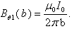 Therefore we can write:
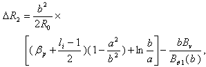 | (11) |
where  is the poloidal beta,
  is the internal inductance of the plasma, and
  is the average vertical magnetic field over the vacuum chamber. We can find
  and Shafranov parameter
  from magnetic coils measurement
 :
: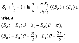 | (12) |
Experimental results are presented in next section.
4. Experimental Results and Comparative between Them
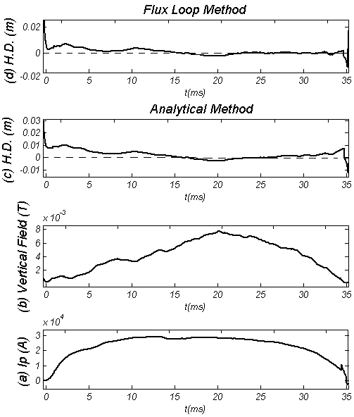 | Figure 2. (a) Plasma current, (b) Vertical magnetic field, (c) Horizontal Displacement (H.D.) determined by the Analytical method, and (d) H.D. determined by the Flux loops method |
For determination of the plasma position using the first method, we needed for measurements of the poloidal magnetic flux around the plasma. Therefore we designed and installed two poloidal flux loops on outer surface of the IR-T1 chamber. Positions of the flux loops presented in the Fig. 1. Also the Shafranov parameter and average vertical field, were obtained from the magnetic probes.According to the Faraday’s law, outputs of all magnetic diagnostics proportional to derivative of the magnetic flux which passing through them, therefore we needed to integrate the output of the flux loops and magnetic probes after compensating their output.We used the above two methods to determining the horizontal displacement in IR-T1. Results presented in the Figure 2. These figures show that two methods are in good agreement with each other. Moreover, we plotted the magnetic flux surfaces for plasma parameters at t=15ms in target shot, displacement of the plasma column center is clearly visible as shown in Figure 3.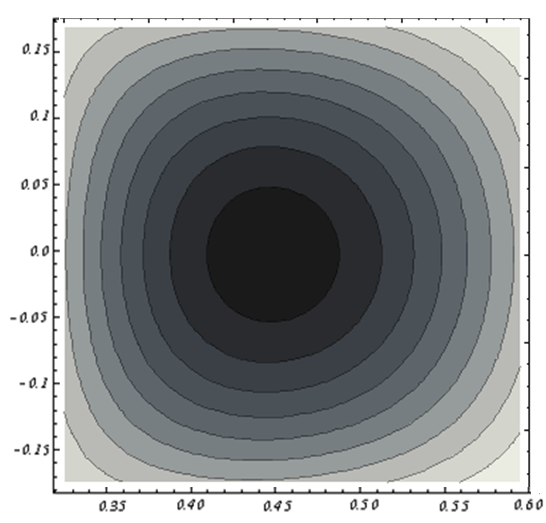 | Figure 3. Magnetic Flux Surfaces obtained by the Analytical Method at t=15ms in Target Shot in IR-T1 Tokamak (clearly the displacement of Plasma Column Center observable) |
5. Summary and Conclusions
In this paper we determined the displacement by two experimental and analytical methods in IR-T1 tokamak. In the first method we designed and installed two poloidal flux loops on the outer surface of the IR-T1 tokamak chamber, and then plasma displacement determined from them. To compare the plasma position obtained using this method, the analytical solution of the Grad-Shafranov equation is also presented, and experimented on IR-T1. Results show that two methods are in good agreement with each other. The acceptable differences between them are because of (1) approximation in measurements of the flux functions on plasma surfaces in flux loops method, (2) the boundary condition in the analytical method, and (3) measurement of the Shafranov parameter with magnetic probes in the analytical method.
References
| [1] | Mukhovatov V. S., and Shafranov V. D. 1971, Nucl. Fusion, 11: 605 |
| [2] | Freidberg J. P. 1987, Ideal MHD, Clarendon, Oxford Press |
| [3] | Guazzotto L. and Freidberg J. P. 2007, Phys. Plasmas, 14: 508 |
| [4] | Shimada M., Campbell D. J., Mukhovatov V., et al. 2007, Nucl. Fusion, 47: S1 |
| [5] | Atanasiu C. V., Gunter S., Lackner K., et al. 2004, Phys. Plasmas, 11: 3510 |
| [6] | Lee G. S., 2001, Nucl. Fusion, 41: 1515 |
| [7] | Seo S. H. 2009, Phys. Plasmas, 16: 032501 |
| [8] | Lee S. G., 2008, Rev. Sci. Instrum, 2008, 79: 10F117 |
| [9] | Donne A. J. H. 2007, Nucl. Fusion, 47: S337 |
| [10] | Najmabadi F. and the ARIES Team 2003, Fusion Eng. Des, 65: 143 |
| [11] | Guazzotto L., Betti R., Manickam J, et al. 2004, Phys. Plasmas, 11: 604 |
| [12] | Salar Elahi A., 2009, J Fusion Energy, 28(4), 346-349 |
| [13] | Atanasiu C. V., 2003, Proceedings of the 30th EPS Conference on Controlled Fusion and Plasma Physics, St. Petersburg, ECA vol. 27A, p-2-104 |
 Abstract
 Reference
 Full-Text PDF
 Full-Text HTML