Ashraf A. El-Saftawy 1, Ahmed Elfalaky 2, Magdi S. Ragheb 1, Safwat G. Zakhary 1
1Accelerators and Ion Sources Department, Nuclear Research Center, Atomic Energy Authority, Cairo, P.O. 13759, Egypt
2PhysicsDepartment, Faculty of Science,Zagazig University, Zagazig, P.O. 44519, Egypt
Correspondence to: Ashraf A. El-Saftawy , Accelerators and Ion Sources Department, Nuclear Research Center, Atomic Energy Authority, Cairo, P.O. 13759, Egypt.
| Email: |  |
Copyright © 2012 Scientific & Academic Publishing. All Rights Reserved.
Abstract
A Pierce-type electron gun with spherical anode has been numerically computer-aided analysed to yield an appropriate beam with suitable properties valid for different applications. It has been proven that, around a certain value of the aspect ratio, 0.75, the resultant beam geometry could be suitably controlled. The gun geometry plays an important role for beam shaping; parallel, converged or diverged. The minimum electric field required to prevent beam expansion due to space charge effect has been estimated and it is found to be proportional to the cubic root of the distance from the anode to the target (Z1/3). Also, it is proved that the minimum beam radius is realized at the minimum beam perveance and the maximum beam convergence angle. As a result, this reveals that, the gun geometry controls the beam emittance. The gun design analysis proposed here helps to choose the better operating conditions suitable for low energy electron beam bombardment and/or injection applications.
Keywords:
Electron Gun, Beam Geometry, Perveance, Emittance
Cite this paper:
Ashraf A. El-Saftawy , Ahmed Elfalaky , Magdi S. Ragheb , Safwat G. Zakhary , "Numerical Simulation of Beam Formation and Transport in an Electron Gun for Different Applications", Journal of Nuclear and Particle Physics, Vol. 2 No. 5, 2012, pp. 126-131. doi: 10.5923/j.jnpp.20120205.04.
1. Introduction
Beams of charged particles and electron beams in particular are being used widely in a great and continuously increasing number of scientific instruments, electron devices and industrial facilities[1-3]. An indispensable part of each electron-optical system is the electron gun in which a beam of accelerated electrons is generated. Although the electron gun is usually only a small fraction of the entire system, its characteristics are crucial for the performance of the whole electron-optical column. Todays, a wide range of electron guns is in use which differs in design, accelerating voltage, power, configuration of the beam and type of the emitter [4-7]. In order to realize the performance requirements of the applied beam it is essential to obtain all possible knowledge of the beam from the electron gun prior to its injection into the system. This gives the opportunity to optimize the gun parameters according to beam characteristics needed and to minimize the tuning time of the system[8]. At the gun exit, to obtain a beam transmission without particles loss, the cross-section of the beam must not exceed a given maximum value of a defined point[2]. To achieve this we will introduce an important quantity known as emittance.The emittance is an important aspect for high-quality beam, which is basically defined as the product of width and transverse velocity spread of the beam (region of phase space occupied by beam). If the beam is densely packed, then the emittance is said to be low and if it is somewhat spread out, it possess high emittance[9-11].In order to adopt the electron gun beam to our laboratory projects, the surface modification of different materials and plasma acceleration experiments, we will use a numerical computer-aided simulation study. According to the gun geometry, the resulting electron beam properties will be studied. In order to perform this theoretical simulation, different gun models are previously studied[12]. The results are compared to the present electron gun design. This is to reveal the parameters and conditions that must be followed to maintain an appropriate output beam matched to the required application.
2. Theoretical Model Description
The models previously studied revealed the presence of multi electron beam distortions. For instance using a plane extraction electrode, an aberration arises in the extracted beams[12]. To overcome this divergent electron flow effect and to study the beam control parameters, a shaped extraction electrode in spherical modelling system will be investigated. In the following analysis of the electron beam system, we will consider the radial electrons flow in spherical coordinate system. The cathode and the anode are parts of concentric spheres with radii of curvatures Rcand Rarespectively. The near cathode focusing electrode is cup shaped with Pierce electrode inside, as shown in Figure 1. The Pierce electrode is designed in condition that the zero potential line is parallel to the beam edge. This condition is achieved when the electrodemakes an angle 67.5o with the beam edge as shown in figure 1. Pierce electrode bends electric fields to generate focusing forces near the source. These electric forces counteract the defocusing beam generated forces on the edge of the beam[2]. The region behind the anode assumes a field free region to the electrons in which the electrons behave according to the inter-forces acting on them. The behaviour of the electron beam in this region will be discussed in order to obtain the factors affecting the electrons motions.  | Figure 1. Electron gun and beam configuration geometry |
3. Results and Discussion
3.1. Gun Geometry Effect on Electron Beam Perveance
The electrons flow in the spherical coordinates system is characterized by[2]: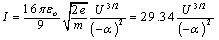 | (1) |
Where, Iis the electrons current,e is the electronic charge, mis the electron mass,U is the applied acceleration voltage and αis the Langmuir-Blodgett function which depends on the gun geometry as seen in the formulae[13]: | (2) |
andδ = ln(Ra/Rc) is a function depending on the gun radii of curvatures of the two electrodes.The connection between the gun geometrical parameters Ra/Rc and the primary angle of convergenceθ, the current Iand the anode voltage Uis determined by[14]: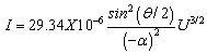 | (3) |
While the equation relating the beam current and the three halves power of the acceleration voltage gives the perveance, in other words the gun perveanceP (in  perv) is given by:
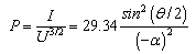 | (4) |
Equation 4 indicates that the perveance of the electron gun also depends on the geometry of the electrodes system (Ra/Rc ,θ)as shown in figure 2 which indicate that we can control the gun perveance not only by the acceleration voltages and the beam current but also by varying the gun geometry. Execution of the simulation shows that the beam perveance increases slowly (figure 2) until before Ra/Rc= 0.75 (the saddle point) after which the beam perveance increases very rapidly.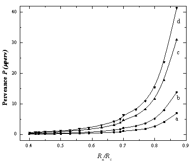 | Figure 2. Dependence of the electron beam perveance on the electrode geometry forθ= a) 0.1 rad, b) 0.2 rad, c) 0.3 rad and d) 0.4 rad |
The increase of the acceleration voltages of the electron beam decreases the beam convergence angle θas seen in the formula[15];θ α (KT/eU)1/2where,Kis the Boltzmann constant and Tis the electron temperature. This means that at higher accelerating voltage, the axial accelerating component of the field has a great effect to collimate the beam and to reduce the spread caused by the transverse component of the electron velocity in the beam. In plasma systems, the shape of the plasma meniscus controls the output beam shape[16, 17] (divergence or convergence), but in thermionic electron guns, a shaping electrode (focusing electrode) is used. This electrode has many shapes and designs according to the gun type to avoid beam dispersion. In the present work, the gun and the focusing electrode shape have been shown in fig 1. This configuration generates a primary convergent electron beam with a primary convergence angleθ.
3.2. Anode Lens Effect
The presence of an extraction electrode (anode) into the beam path has many effects. The anode aperture modifies the electric field in that electron gun. The radial electric field defocuses the exiting electrons[2,18]. The fields act like an electrostatic lens with negative focal length. The defocusing action is called the negative lens effect. Also the anode aperture reduces the axial electric field at the centre of the cathode leading to a depressed beam current density. The focal length fof the aperture negative action is[2, 14]: | (5) |
Where,Eais the axial electric field near the anode which is given by: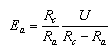 | (6) |
Where Ra/Rc is known as the aspect ratio. Eq.5 could be rewritten as: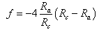 | (7) |
By dividing both sides of eq 7 by Rc, we get: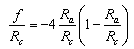 | (8) |
It follows from eq.7 and eq. 8 that the focal distance of the anode lens depends only on the relation between the cathode and the anode radii of curvatures i.e. the gun geometry. This dependence is shown in Fig 3.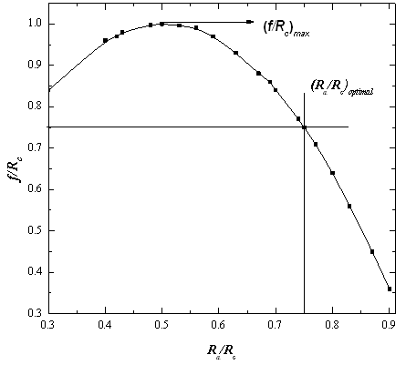 | Figure 3. Dependence of the focal length of the anode lens on the electrode geometry |
Due to the refracting property of the anode lens, the angle of electron beam convergence at the exit of the gun γis less than the initial convergence angleθ. Anglesθ and γare connected by:γ = θ - σ, whereσ≅ tanσ = ra/f is the electron beam refracting angle due to the anode lens. Herera = Rasinθ≅Raθ is the beam radius at the anode aperture radius. Then,is given by: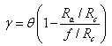 | (9) |
With the aid of eq. 9, it is easy to find the angle γby plotting a calibration diagram between 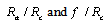 as seen in figure 3. From eq. 9, it could be seen that, a parallel beam is obtained when γ = 0 at Ra/Rc=f/Rc. This condition is achieved when the aspect ratio Ra/Rc=0.75 as deduced by eq. 8 and figure 3. Figure 3 indicates that, as the aspect ratio Ra/Rcincreases, f/Rc value increases up to a certain value (f/Rc)maxat which the focal point is very close to the anode and the angle of convergence is very large. This means that the beam is much focused. By further increase of Ra/Rc, the focal point get apart from the anode up to a certain value[(Ra/Rc)optimal = 0.75] after which the beam becomes convergent again. The previous discussion reveals that the resulting beam properties could be controlled by choosing appropriate gun geometry. Figure 4 shows the decrease of the convergence angle with the decrease of the aspect ratio (Ra/Rc) up to a certain value[(Ra/Rc)optimal = 0.75] after which the beam lines make a crossover with the z-axis and this means that the aberration begins to appear in the beam. This explains also why the electron beam perveance increases very rapidly after the optimal value of the aspect ratio as shown in figure 2. This result is also proved by eq 9 and figure 3.
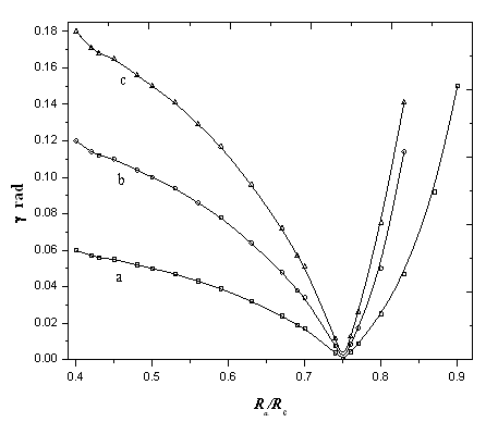 | Figure 4. Dependence of the beam convergence angle on the gun geometry forθ= a) 0.1 rad, b) 0.2 rad and c) 0.3 rad |
The above discussion could be summarized as follows:• When (Ra/Rc)=0.75, the angle γ=0, i.e. at the exit of the gun the beam current will be parallel to the beam axis• When (Ra/Rc)>0.75, the beam will be convergent.• When (Ra/Rc)<0.75, the beam will be divergent.By controlling the electron gun geometry, we can control the shape (divergent, parallel, and convergent) of the output beam. This property is used to produce guns with different output electron beam properties as: • Flood guns which produce a wide-angled beam, we will use this type in solids and polymers surfaces treatments experiments.• Focusable guns which produce a small spot beam, we will use this type in plasma acceleration experiments.
3.3. Equi-Potential Lines effect on Electron Beam Shape
In order to study the effect of the equi-potential lines on the beam geometry and shape, a computer program known as SIMION 3D version 7 has been used. The electric field distribution between the cathode and the anode for different acceleration voltages are shown in fig 5. According to the potential field lines distribution, the beam is shaped. The field lines between the cathode and the anode which represent a positive lens (focusing lens), the beam is focused when entering the positive lens. Also the beam is defocused again leaving the anode aperture and it enters the negative lens outside the gun in the field free region. 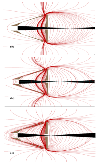 | Figure 5. Equi-potential lines distribution and the beam shape for different acceleration voltages; a) 25kV, b) 50kV and c) 75kV |
The field lines shapes and curvatures (concave or convex) are determined according to the electrode geometry and the acceleration voltages. In the present work, the pierce electrode with the spherical anode form a positive lens between them resulting in a focused beam. The output beam is defocused as it gets far away from the anode due to the electric field reduction.As could be seen in fig 5, the focal point of the anode lens gets closer to the anode as the acceleration voltages increase. The focal lengths are 120 mm, 66 mm and 20 mm at acceleration voltages 25 kV, 50 kV and 75 kV respectively. This means that the electron beam becomes more converged, i.e. the electron beam emittance is very low. The beam with low emittance will be used in the plasma acceleration experiments; in this case the plasma tube will be mounted at the focal point of the gun. As we get apart from the anode, the electron beam become wider and the beam emittance become larger. At this region the solids and polymers samples will be mounted for irradiation experiments.
3.4. Minimum Electric Field Required to Prevent Space Charge Effect
A beam with appreciable space charge cannot be transported over a long distance without using strong fields. It is of interest to have a guide relating the rate of acceleration of the electron beams to the space charge (i.e. beam current). From such a guide an approximate value of the electric field which prevents beam expansion could be obtained[16]. The mathematical basis for the design of an electron gun follows from analysis of one dimension flow between two parallel electrodes. One of them is the emitter (cathode) and the other is the extractor (anode). It is evident that the field intensity components Ez ≠ 0 &Ex=Ey=0. Also all electrons have only one velocity νz normal to the electrode surface. The potential distribution inside the beam can be described by the Poisson's equation as[16]: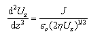 | (10) |
Where Uz is the potential in the plane parallel to the electrodes and positioned at distance Z from the cathode, J is the current density of the space charges emitted,  is the electron charge to mass ratio. Equation 10 is a differential equation of the second order which has the following solution:
 | (11) |
Where A=5.69 x 10³J2/3,J=2.33x10-6(Uz)3/2/z2(A/m2). The minimum axial electric field required to prevent beam expansion due to space charge effect (Er = 0), could be obtained from eq.11 which is: | (12) |
It has been proven that the gun geometry controls the resulting beam shape. Beside these geometrical parameters, there exist the electric fields that will be used to transport the electron beam from the gun to the target. By controlling this electric field, the electron beam geometry could be controlled to match the required application. The applied electric field could be used as a fine tuner to adjust the beam properties (size, diameter, divergence, emittance, etc.).
3.5. Electron Beam Waist
The electron beam motion in the field free region located behind the gun anode is determined by the actions of coulomb’s forces. In other words, the beam emerging the aperture of a converging gun has strong space charges forces and low emittance. In this region, the anode the field intensity inside a beam of radius r and carrying currentI distributed uniformly across the beam is given by[4]: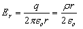 | (13) |
Where q is the beam space charge per unit volume  is the space charge density per unit area within unit length. If
 at the beam boundary
 , then;
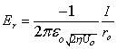 | (14) |
The equation of motion of the electron in the radial direction is: | (15) |
Consider , by differentiating with respect to z;
  , Eq. (15) can easily be transformed to[19]:
 | (16) |
In terms of the perveance and beam radius where , eq. (16) takes the form:
 | (17) |
The solution of the above second differential equation gives the minimum beam radius at the waist in terms of the envelope angle (converging angle)γand the beam perveance Pat the anode as: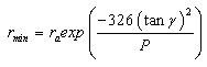 | (18) |
Where P is in  perv= 10-6 A/V3/2.The above analysis shows that, the minimum focused radius of a beam rmin (at the beam waist) and the distance from the gun to this waist are related to the beam slope and beam perveance. In order to achieve a small beam size and low emittance, the beam must be of low perveance with high initial convergence slope, as shown in fig 6. From fig. 4 and fig. 6, it could be seen that, as the aspect ratio Ra/Rc increase, the beam slope decreases and hence the minimum beam radius decreases. This means that the beam emittance decreases with the decrease of the aspect ratio. Also, as Ra/Rc increases, the beam slope increases and hence the minimum beam radius increases too. This leads to the increase of the beam emittanceHigh emittance electron beam is a good choice for irradiation experiments. In our work, it will be used in experiments of surface modification of polymers and solids. On the other hand, Low emittance electron beam is a desirable property for many applications. We will use the low emittance electron beam in studying the interaction of electron beam with plasma, which leads to the promising phenomena of plasma acceleration.
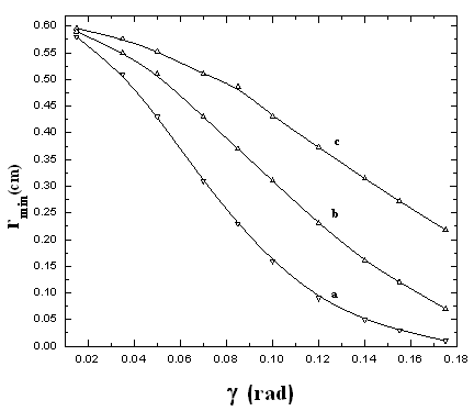 | Figure 6. Dependence of the minimum output beam radius on the electrode geometries and for P = a) 0.25  perv, b) 0.5 perv, b) 0.5  perv and c) 1 perv and c) 1  perv perv |
4. Conclusions
The design of the gun and the working conditions proposed here helps both operators and designers of the electron guns to choose best operating condition suitable for each application. It could be concluded that:1. By controlling the electron gun geometry, we can control not only the Electron beam intensity, perveance and emittance but also the beam shape (divergent, parallel, and convergent).2. The estimation of the minimum electric field required to prevent the electron beam expansion is found to be proportional to one thirds power of the distance from the anode to the target (Z1/3).3. The smallest beam size is achieved in condition that the gun beam perveance is as low as possible and the convergence slope is very high. This leads to electron beams of low emittance which is desirable in some applications. On the other hand, high emittance electron beam could be obtained which is favoured for some other applications. Finally, we can conclude that by controlling the gun geometry and regulating its operation conditions, we can validate the output electron beam geometry for a wide range of applications.
References
| [1] | J.D. Lawson, “The Physics of Charged-Particle Beams”, 2nd Ed. Oxford, Claredon, 1988. |
| [2] | S. Humphries, “Charged Particle Beams”, Wiley, New York, 1990 |
| [3] | P.W. Hawkes, E. Kasper, “Principles of Electron Optics”, Academic Press, London, San Diego, 1989. |
| [4] | S. Sabchevski, G. Mladenov, A. Titov, I. Barbarich, “Modeling and Simulation of Beam Formation in Electron Guns”,Nucl. Instr. and Meth. in Phys. Res. A381, 185-193, 1996. |
| [5] | S.K. Mahapatra,S.D. Dhole, V.N.Bhorastar, “A 20 keV Electron Gun System for the Electron Irradiation Experiment”,Nucl. Instr. and Meth.in Phys. Res. A 536, 222- 225, 2005. |
| [6] | C.Y. Ruan, M. Fink, “Emission Optics of Steigerwald-Type Electron Gun”, Rev. Sci. Instrum. 70 (11), 4207, 1999. |
| [7] | A.V. Deore, B.J. Patil, V.N. Bhoraskar, S.D. Dhole, “Design, Development and Characterization of Tetrode Type Electron Gun System for Generation of Low Energy Electrons”, Indian Journal of Pure & Applied Physics, Vol. 50, 482-485, 2012. |
| [8] | M.S. Ragheb, M.H.S. Bakr, “Improvement of Auger Spectra Using A.C. Modulation Technique”, Radiat. Phys. Chem. 47 (5), 673-675, 1996. |
| [9] | M. Reiser,“Theory & Design of Charged Particle Beams, Wiley”, New York, 1994. |
| [10] | G. Herrmann, “Optical Theory of Thermal Velocity Effects in Cylindrical Electron Beams” J. Appl. Phys.29 (2), 127, 1958. |
| [11] | K. Masood, M. Iqbal, M. Zakaullah, “Emission Characteristics of the Thermionic Electron Beam Sources Developed at EBSDL”, Nucl. Instr. and Meth in Phys. Res. A 584, 9-24, 2008. |
| [12] | A. Hassan, A. Elsaftawy,S.G. Zakhary, “Analytical Studies of the Plasma Extraction Electrodes and Ion Beam Formation”, Nucl. Instr. and Meth. in Phys. Res. A 586, 148-152, 2008. |
| [13] | S.E. Tsimring,“Electron Beams and Microwave Vacuum Electronics”,Wiley, New York, 2007. |
| [14] | A. Asi,“Boundary Element Method (BEM) for Charged Particles Optics”, Proc. Charged Particle Detection, Diagnostics, and Imaging, Delage O, Munro E and Rouse J A, (Eds); SPIE Vol. 4510, P. 138-147, 2001. |
| [15] | M.E. Abdelaziz,S.G. Zakhary, A.A. Ghanem,“Broad Beam Ion Implanter with the Use of Radio Frequency Ion Source”, XVII international symposium on Discharges and Electrical Insulation in Vacuum, Berkely, IEEE, 1996. |
| [16] | R.G. Wilson, G.R. Brewer, “Ion Beams with Application to Ion Implantation”, Wiley, New York, 1973. |
| [17] | A.T. Forrester,“Ion Beams Fundamental of Generation and Propagation”, Wiley, New York, 1988. |
| [18] | M.M. Abdelrahman, S.G. Zakhary, “Simulation Studies for Ion Beam Extraction Systems”, Brazilian J. of Physics, vol. 39, no.2, 275-279, 2009. |
| [19] | A. Zhigarev, “Electron Optics and Electron Beam Devices”, Mir Publisher, Moscow, 1975. |
 Abstract
 Reference
 Full-Text PDF
 Full-Text HTML