Ahmad Salar Elahi , Mahmood Ghoranneviss
Plasma Physics Research Center, Science and Research Branch, Islamic Azad University, Tehran, Iran
Correspondence to: Ahmad Salar Elahi , Plasma Physics Research Center, Science and Research Branch, Islamic Azad University, Tehran, Iran.
| Email: |  |
Copyright © 2012 Scientific & Academic Publishing. All Rights Reserved.
Abstract
In this contribution we will presented comparison of two techniques in order to investigate of the effects of internal inductance on tokamak plasma position, based on a toroidal flux loop (diamagnetic loop) and magnetic probes measurements. For this purpose, a diamagnetic loop with its compensation coil, and also array of magnetic probes were designed, constructed, and installed on outer surface of the IR-T1 tokamak chamber, and then the poloidal beta and poloidal and radial magnetic fields obtained. Moreover a few approximate values of the internal inductance for different possible profiles of the plasma current density are also calculated. Then, the Shafranov parameter and also the Shafranov shift were determined. Experimental results compared. Comparison of results on IR-T1, show that (1) by increasing the internal inductance from one, plasma column shifted inward, and also (2) IR-T1 plasma current density profile relate to the power of  approximately.
Keywords:
Tokamak, Plasma Position, Plasma Internal Inductance, Diamagnetic Loop, Magnetic Probe
1. Introduction
An equilibrium plasma position is one of the important problems of tokamak experiments. Equilibrium is a condition for which plasma pressure is balanced by electromagnetic force (Lorentz force). Tokamak plasma equilibrium is a significant fraction of the fusion program studies in order to achieve tokamaks optimized operation and become close to Lawson criterion. Determination of precise plasma position during confinement time is essential to transport it to the control system based on feedback.Magnetic diagnostics, in particular toroidal flux loop (diamagnetic loop) are commonly used in tokamaks to measure the variation of toroidal flux induced by the plasma. From this measurement, the total diamagnetic energy content and the confinement time of the plasma can be obtained as well as the poloidal beta. On the other hand, the magnetic fields distribution outside the plasma and then the Shafranov shift depend on the combination of  via the Shafranov parameter (asymmetry factor)
  . If
. If  is known from the anyway, then measurement of the Shafranov parameter and poloidal magnetic field gives a value of the Shafranov shift. The value of
  is determined by the radial distribution of toroidal current profile of the plasma[1-15]. In this paper we present two magnetic techniques based on the diamagnetic loop and magnetic probe for determination of the poloidal Beta and poloidal magnetic field, and moreover an approximated method for determination of the plasma internal inductance, and therefore the Shafranov parameter and Shafranov shift in IR-T1 Tokamak, which it is a small, low
 and large aspect ratio tokamak with a circular cross section (see Table 1). Details of the theoretical approach for these magnetic techniques will present in section 2. Details of the diamagnetic loop and magnetic probe methods for determinations of the poloidal Beta and poloidal magnetic field will be discussed in section 3. Details of approximate method for calculation of the internal inductance will present in section 4. Experimental results for determination of the poloidal magnetic field, Shafranov parameter, and Shafranov shift will be discussed in section 5. Summary and discussion will present in section 6.
| Table 1. Main parameters of the IR-T1 tokamak |
| | Parameters | Value | | Major Radius | 45 cm | | Minor Radius | 12.5 cm | | Toroidal Field | < 1.0 T | | Plasma Current | < 40 kA | | Discharge Time | < 35 ms | | Electron Density | 0.7-1.51013m-3 |
|
|
2. Theoretical Approach for Determination of the Shafranov Shift Based on the Diamagnetic Loop and Magnetic Probe
Shafranov parameter and therefore Shafranov shift relate to the distribution of magnetic fields around the plasma current. Therefore, those can be written in terms of the tangential and normal components of the magnetic field on the contour  (see Fig. (2)). Distribution of the poloidal and radial magnetic fields are can be written in the first order of the inverse aspect ratio as follows, respectively[1,5]:
 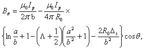 | (1) |
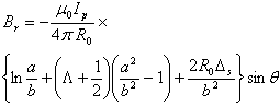 | (2) |
where  is the major radius of the vacuum vessel,
  is the Shafranov shift,
  is the plasma current, a and b are the minor plasma radius and minor chamber radius respectively, and
  is the Shafranov parameter. These equations accurate for low
 plasma and circular cross section tokamaks as IR-T1, and where:
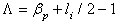 | (3) |
where  is the poloidal Beta, and
  is the plasma internal inductance. Rearranging of the Eq. (1) give us:
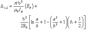 | (4) |
Also with combination of Eq. (1) and Eq. (2), we have: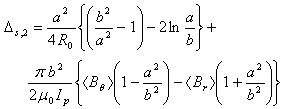 | (5) |
where 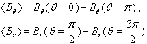 | (6) |
Therefore, with combination of the magnetic field and poloidal Beta measurements, and also calculation of the internal inductance, Shafranov shift can be determined from Eq. (4).In order to investigate the effects of the internalinductane on determination of plasma position, we used the Eq. (4) and then results compared with results of Eq. (5) in IR-T1.
3. Magnetic Probe and Diamagnetic Loop for Determinations of the Magnetic Field and Poloidal Beta
In general the magnetic sensors (magnetic probe or diamagnetic loop) works by Faraday’s law and measures component(s) of the local magnetic fields or magnetic fluxes for use in plasma control, equilibrium reconstruction and detection of plasma energy, poloidal beta and MHD instabilities.Magnetic probe consists of a coil in solenoidal form, which whose dimensions are small compared to the gradient scale length of the magnetic field. A total magnetic flux passed through such a coil is  , where n is the number of turns of coil, A is the average area of cross section of coil, and B is the local magnetic field parallel to the coil axis.The induced voltage in the magnetic probe and then magnetic field is:
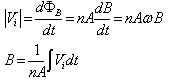 | (7) |
where  is the frequency of the fluctuations of the magnetic field. Therefore in order to measurement of the magnetic field distribution we must be integrating the output signals of the magnetic probe.On the other hand, diamagnetic loop measures the toroidal diamagnetic flux for the purpose of measurement of the poloidal beta and thermal energy of the plasma. The toroidal flux that produced by the plasma is related to the total perpendicular thermal energy of the plasma. Thisdiamagnetic flux is usually measured with the diamagnetic loop. It is usually a single wire which circling the plasma column either inside or outside of the plasma vacuum chamber.Intrinsically this loop will also pickup the toroidal magnetic flux from the toroidal field coil and any current circulating in the poloidal plane, in particular toroidal field coil current, eddy currents in the conducting vacuum chamber induced during transient changes in the plasma energy and plasma current. In other words, the diamagnetic loop consist of a simple loop that links the plasma column, ideally located in a poloidal direction in order to minimize detecting the poloidal field. In cases of the ohmically heated tokamaks (low beta) where the plasma energy density is small compared to the energy density of the magnetic field, the change in the total toroidal magnetic flux is small. Therefore a reference signal equal to the vacuum toroidal magnetic flux is usually subtracted from it, giving a net toroidal flux equal to the diamagnetic flux
  produced by the circular plasma. Relation between the diamagnetic flux and the poloidal beta derived from simplified equilibrium relation[2,3,6] is:
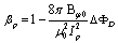 | (8) |
where  and where
  where
where is the toroidal magnetic field in the absence of the plasma which can be obtained by the magnetic probe or diamagnetic loop,
  is the plasma current which can be obtained by the Rogowski coil,
  is the toroidal flux because of toroidal field coils,
  and
and  are the passing flux through loop due to possible misalignment between ohmic field and vertical field and the diamagnetic loop and
  is the toroidal field due to eddy current on the vacuum chamber. These fluxes can be compensated either with compensation coil or fields discharge without plasma. It must be noted that compensating coil for diamagnetic loop is wrapped out of the plasma current, and only the toroidal flux (which is induced by the change of toroidal field coil current when plasma discharges) can be received. As shown in Eq. (8) the diamagnetic loop signal contains two parts, plasma diamagnetic flux and the vacuum toroidal flux. So the diamagnetic flux
  caused by plasma current can be measured from the diamagnetic and compensating coil using subtraction. According to above discussion, we designed, constructed, and installed four magnetic probes and also diamagnetic loop with its compensation coil, on outer surface of the IR-T1, in order to determinations of the magnetic fields distribution and poloidal Beta. Plasma current is also obtained with Rogowski coil. But, in determination of the Shafranov shift with Eq. (4), we needed to calculation of the internal inductance, where in next section approximate method presented.
4. Approximate Methods for Calculation of the Plasma Internal Inductance
The internal inductance of the plasma per unit length, normalized to  can be determined from the conservation of zeroth order magnetic energy:
 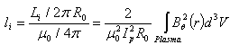 | (9) |
For typical profile of the poloidal field which correspond to flat current density profile  (usually accurate for low beta tokamak), as:
 | (10) |
Then first approximate value for the internal inductance can be easily obtained by substituting Eq. (10) in Eq. (9):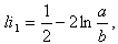 | (11) |
where this relation for IR-T1 tokamak parameters equal to value of 0.994.Second approximate value for the internal inductance can be determined from the well-known Bennett current density profile, as: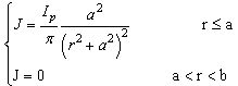 | (12) |
therefore, the poloidal magnetic field profile can be obtained: 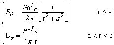 | (13) |
and then second approximate value for internal inductance can be obtained: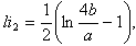 | (14) |
where this relation for IR-T1 tokamak parameters equal to value of 0.332.In general case, for the large aspect ratio and circular plasma, the current density distribution is[4]: 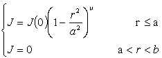 | (15) |
The poloidal magnetic field profile can be obtained: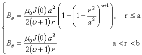 | (16) |
where 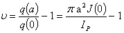 | (17) |
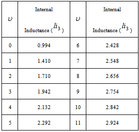
If we assume a more peaked current profile with central safety factor , then the values of the internal inductances can be determined from substituting the Eq. (16) in Eq. (9), as a function of the
  . Results present in table 2 and Figure (1).
Table 2. dependence of the Internal Inductance to the values of
 for IR-T1 tokamak parameters for IR-T1 tokamak parameters
 |
| |
|
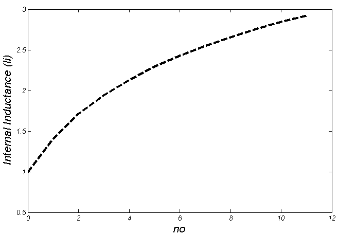 | Figure (1). dependence of the Internal Inductance to the values of  for IR-T1 tokamak parameters for IR-T1 tokamak parameters |
Our experiments show that the value of  which proportional to the edge safety factor reduced from 8 to 1 along time interval of plasma current (see Figure (2)). Therefore, according to recent method, IR-T1 tokamak plasma internal inductance reduced from 2.5 to 1.2 along the time interval of plasma current.
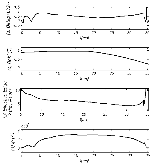 | Figure (2). combination of the Diamagnetic Loop and Magnetic Probe Results: (a) Plasma Current, (b) Effective Edge Safety Factor, (c) Toroidal Magnetic Field, and (d) Shafranov Parameter |
Extremity, our final approximate method for determi -nation of the internal inductance is experimental method. In this method firstly Shafranov parameter is obtained from the magnetic probe measurements, and then the values of the poloidal Beta which obtained from diamagnetic loop, subtracted from it.With combination of Eq. (1) and Eq. (2), we can find the value of the Shafranov parameter as: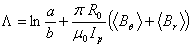 | (18) |
where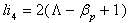 | (19) |
For this purpose, a diamagnetic loop with its compensation coil, and also an array of magnetic probes were designed, constructed, and installed on outer surface of the IR-T1 tokamak chamber (see Figures (4), (5)), and then the poloidal Beta and poloidal and radial magnetic fields obtained from them. As shown in Figure (3), the values of the internal inductance reduced from 2 to 0.61 along the time internal of the plasma current.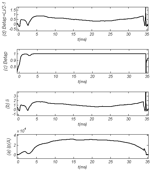 | Figure (3). combination of the Diamagnetic Loop and Magnetic Probe Results: (a) Plasma Current, (b) Internal Inductance obtained by Subtraction of Poloidal Beta (c), from Shafranov Parameter (d). As observable, the internal inductance reduces from 2 to 0.61 |
5. Experimental Results and Comparison between Them
In the IR-T1 tokamak an array of four magnetic probes were designed, two magnetic probes were installed on the circular contour  of the radius
  in angles of
  and
and  to detect the tangential component of the magnetic field
  and two magnetic probes are also installed above,
  , and below,
  , to detect the normal component of the magnetic field
  , as shown in Figures (4), (5).
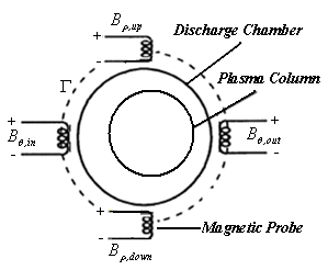 | Figure (4). ons of the four magnetic probes on the outer surface of the IR-T1 tokamak chamber |
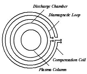 | Figure (5). itions of the diamagnetic loop with its compensation coil on the outer surface of the IR-T1 tokamak chamber |
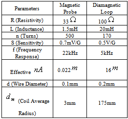
Table 3. Design parameters of the magnetic probe and diamagnetic loop
 |
| |
|
After measurements  and
and  from magnetic probes,
  from Rogowski coil, poloidal Beta from diamagnetic loop and substituting them in to above relations, the internal inductance, Shafranov parameter, and Shafranov shift were obtained. Design parameters of the magnetic pickup coils present in Table 3. Diamagnetic loop and its compensating coil also were constructed and installed on the IR-T1 tokamak. Its characteristics are also shown in Table 3.We used the electric circuit as shown in Figures (6) and (7), for the measurements of induced voltage
  in the diamagnetic loop and magnetic probes, respectively:
 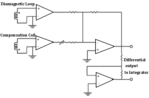 | Figure (6). electric circuit for diamagnetic loop and its compensation coil |
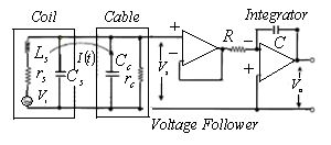 | Figure (7). electric circuit for the magnetic probes |
As shown in the Fig. (7),  is the current in the magnetic probe circuit and
  is the coaxial cable output signal. The application of Kirchhoff’s voltage law for this circuit yields the following equation:
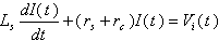 | (20) |
where  is the probe resistivity and
  the cable resistivity and
  probe self-inductance. Therefore for the steady state portion of the plasma current and according to electric circuit, for output signals of the probes, we have:
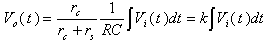 | (21) |
where,  is the integrator time constant, and Eq. (19) is the integrating output of the probe signal. Moreover
  is the inductive voltage supplied by each one of the magnetic pickup coils or diamagnetic loop, where installed around the vacuum chamber of the IR-T1 tokamak.Therefore, by substituting the Eq. (7) in Eq. (21), in case of the magnetic pickup coils the magnetic field can be obtained from:
 | (22) |
And in the case of diamagnetic loop, diamagnetic flux can be obtained from: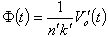 | (23) |
 | Figure (8). (a) Plasma current, (b) Vertical magnetic field, and (c) Horizontal Displacement (H.D.) obtained from the magnetic probes |
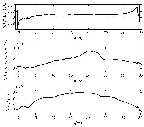
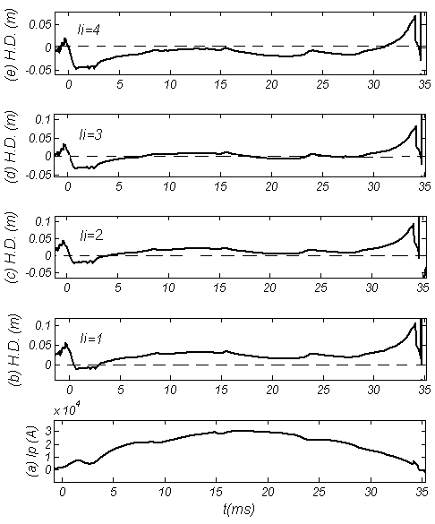 | Figure (9). (a) Plasma current, (b) Horizontal Displacement (H.D.) obtained with combination of the magnetic probe, diamagnetic loop, and approximate values of the internal inductance (Eq. (4)), for li=1, (c) H.D. for li=2, (d) H.D. for li=3, and (e) H.D. for li=4. As shown, by increasing the internal inductance from one, plasma shifted inward (in case of li=2, Horizontal Displacement close to results of first method) |
According to above discussion, firstly we determined the Shafranov shift from the Eq. (5), which only depends to magnetic probes and Rogowski coil data (see Figure (8)). Then, to compare the results we also determined the Shafranov shift from Eq. (4), which depends to the magnetic probes and diamagnetic loop data, and also the approximate values of internal inductance (see Figure (9)).Results of comparing the two methods show that IR-T1 tokamak plasma current density relate to li=2 (corresponding to ).
).
6. Summary and Conclusions
Array of magnetic probes and also diamagnetic loop have been designed, constructed, and installed on the outer surface of the IR-T1 tokamak chamber. The poloidal and radial components of the magnetic fields and also diamagnetic flux signal obtained, and therefore the Shafranov parameter and poloidal beta were measured from them. Then, a few approximate values of the internal inductance calculated, therefore the Shafranov shift determined.To compare, the Shafranov shift obtained independently from the magnetic probes measurements. Results of comparing the two methods show that by increasing the values of internal inductance from one, plasma column shifted inward, and also IR-T1 plasma current profile relate to the power of  .
.
References
| [1] | V. S. Mukhovatov and V. D. Shafranov: Nucl. Fusion 11, (1971), 605 |
| [2] | E. J. Strait and et.al. Magnetic Diagnostics, Fusion Science and Technology, Vol. 53, 2006, pp. 304-330. |
| [3] | I. H. Hutchinson, Principles of Plasma Diagnostics, Cambridge University Press, Cambridge, 1987, pp. 10–33. |
| [4] | J. Wesson, Tokamaks, Clarendon, Oxford, 1997, pp. 105–131. |
| [5] | Hiromasa Niomiya and Norio Suzuki, Japanese Journal of Applied Physics, Vol. 21, No.9, September, 1982, pp. 1323-1327. |
| [6] | A. Salar Elahi et al., J. Fusion Energy 28 (4), 346-349, (2009), DOI: 10.1007/s10894-009-9198-x |
| [7] | A. Salar Elahi et al., J. Fusion Energy 28 (4), 416-419, (2009), DOI: 10.1007/s10894-009-9215-0 |
| [8] | A. Salar Elahi et al., J. Fusion Energy 28 (4), 408-411, (2009), DOI: 10.1007/s10894-009-9213-2 |
| [9] | A. Salar Elahi et al., J. Fusion Energy 28 (4), 412-415, (2009), DOI: 10.1007/s10894-009-9214-1 |
| [10] | A. Salar Elahi et al., J. Fusion Energy 28 (4), 394-397, (2009), DOI: 10.1007/s10894-009-9210-5 |
| [11] | A. Salar Elahi et al., J. Fusion Energy 28 (4), 404-407, (2009), DOI: 10.1007/s10894-009-9212-3 |
| [12] | M. Emami, M. Ghoranneviss, A. Salar Elahi and A. Rahimi Rad, J. Plasma Phys. 76 (1), 1-8, (2009), DOI: 10.1017/S0022377809008034 |
| [13] | A. Salar Elahi et al., Journal of Nuclear and Particle Physics 1(1), (2011), 10-15, DOI: 10.5923/j.jnpp.20110101.03 |
| [14] | A. Salar Elahi et al., Journal of Nuclear and Particle Physics 2(2), (2012), 1-5, DOI: 10.5923/j.jnpp.20120202.01 |
| [15] | M. Ghasemloo, M. Ghoranneviss, A. Salar Elahi et al., Journal of Nuclear and Particle Physics 2(2), (2012), 22-25, DOI: DOI: 10.5923/j.jnpp.20120202.05 |
 Abstract
 Reference
 Full-Text PDF
 Full-Text HTML