-
Paper Information
- Next Paper
- Paper Submission
-
Journal Information
- About This Journal
- Editorial Board
- Current Issue
- Archive
- Author Guidelines
- Contact Us
Journal of Nuclear and Particle Physics
p-ISSN: 2167-6895 e-ISSN: 2167-6909
2012; 2(3): 26-30
doi: 10.5923/j.jnpp.20120203.01
Modified Saddle Field Ion Source Using A Ring Focusing Electrode
M. M. Abdelrahman, F. W. Abdelsalam
Accelerators & Ion Sources Department, Nuclear Research Center, Atomic Energy Authority P.N.13759, Inchas, Cairo, Egypt
Correspondence to: M. M. Abdelrahman, Accelerators & Ion Sources Department, Nuclear Research Center, Atomic Energy Authority P.N.13759, Inchas, Cairo, Egypt.
| Email: |  |
Copyright © 2012 Scientific & Academic Publishing. All Rights Reserved.
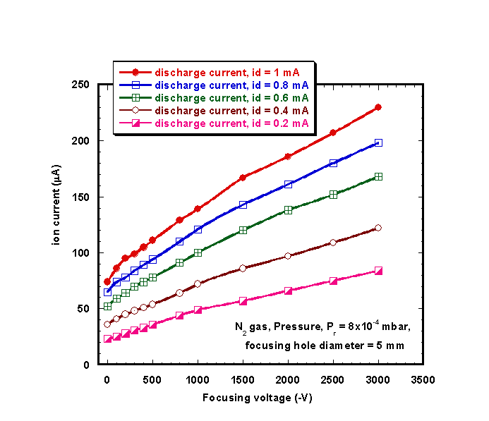
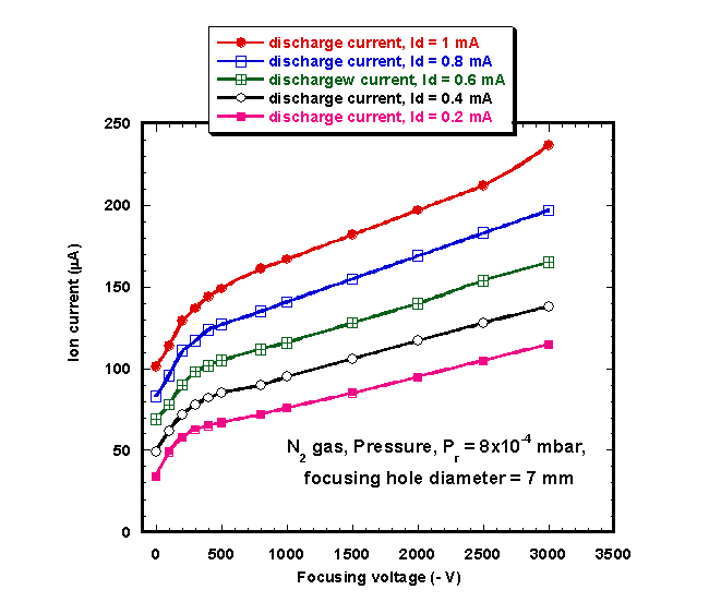
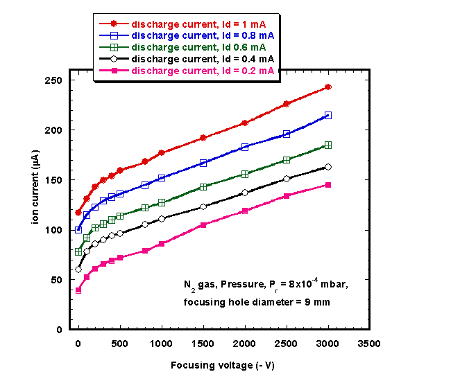
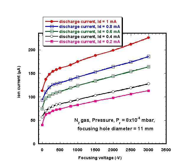
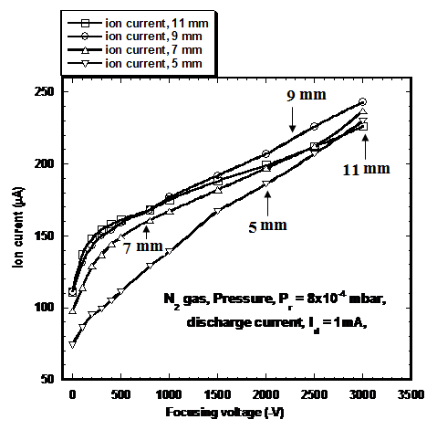
An experimental study of a dc saddle field ion source is reported with a view to maximizing the beam current and insuring extended operation of the source. The dependence of the beam current on geometrical and operational parameters is studied. The electrical characteristics of a dc saddle field discharge were studied using nitrogen gas. This study includes the experimental arrangement for ion beam production from nitrogen gas under the influence of discharge voltages applied to the focusing electrode. Also, different focusing hole diameters are examined and optimized to get a highest efficiency of the ion source. A focusing electrode in the form of a ring is placed at 4 mm from the ion source exit. Different ring electrodes with different exit hole diameters (5, 7, 9, and 11 mm) were used as focusing electrodes. The optimum hole diameter for the focusing electrode was found to be 9 mm where maximum ion beam current can be obtained. It was found that at 9 mm hole diameter, focusing voltage = - 3 kv, and pressure Pr = 8x10⁻⁴ mbar using nitrogen gas at distance between two anode rods= 6 mm, discharge region = 5 mm, an ion beam current of 243 µA could be obtained. These data are important for ion beam sputtering, ion beam thinning and in other several applications.
Keywords: Focusing Electrode, Plasma Production, Ion Beam And Nitrogen Gas Pressure
Article Outline
1. Introduction
- Ion sources are used in many research fields such as mass separation, ion implantation, fusion, atomic physics and a variety of accelerators for spectroscopy, nuclear and particle physics with different requirements. In most saddle field ion sources, the ions are produced by an electrical discharge through a gas or a vapor at pressure in the range of 10-3 mbar. The discharge creates an ionized medium, plasma, of high electron and ion densities. The adjustable parameters of an ion source are voltage across the discharge, the gas pressure, the gap distance between electrodes, size of the ion exit aperture, geometry and surface properties of the electrodes and the shape and dimensions of the discharge vessel. Ion sources are one of the important components of particle accelerators[1 for studying various nuclear reactions and are essential part of all mass spectrometer[2. Also they are useful tools in vacuum technology, ion etching, ion sputtering and ion implantation[3. Ion implantation has been used to modify the mechanical properties of a wide range of metals[4 and alloys using plasma techniques for ion sources[5, 6. Saddle field ion sources are advanced compact ion and fast atom sources for use in a wide range of applications[7- 9] where small size and high beam intensity are required. Applications include small-scale substrate cleaning and etching, ion beam sputtering of thin films, transmission electron microscope, specimen thinning, fast ion bombardment for mass spectrometry and secondary ion mass spectrometry.In this work, electrical characteristics of a dc saddle field discharge are studied using nitrogen gas. This study includes the experimental arrangement for ion beam production from nitrogen gas under the influence of discharge voltages applied to the focusing electrode. In addition, different focusing hole diameters are examined and optimized to get a highest efficiency of the ion source.
2. Theoretical Considerations
- There are a great many highly interactive considerations that all add up to good overall design of the beam formation and acceleration electrode system. Various different kinds of extractors and focusing systems are considered, for the formation of different kinds of beams. After the beam is formed it must inevitably be transported away from the source and toward the application region. This beam must be passed through a vacuum tube of some sort with minimal loss[10, 11]:
 | (1) |
 is electric field strength and d is the distance between the electrodes.The first condition imposed on ion source plasma is that its density must match the applied extraction field to yield a low divergence beam. Uniform ion emission is required across the whole outlet area. This requirement implies that the plasma column must be wider than that the outlet aperture.The total ion beam current that can be formed from a cylindrically-symmetric extraction system is then given by the expression:
 | (2) |
 is the permittivity, e is the electron charge,
  is the ion charge state, m is the atomic mass, S = r /d is the aspect ratio, r is the radius of the hole of the focusing (extraction) electrode. S is constant for a given extraction (focusing) system, and therefore the extractable ion current is proportional to U3/2 . The proportionality constant is called the perveance P:
 | (3) |
 | (4) |
 constant
  | (5) |
 the ion mass in atomic units. Therefore the ion current for a specific ion species is a function of the aperture radius only. In our study, optimization of a focusing electrode was done by varying the exit hole diameters as well as the focusing voltage and in all cases, searching for the matching ion current density.
3. Description of the Ion Source
- The saddle field ion source (Fig. 1a) consists of two copper anode rods surrounded by a cylindrical cathode. The two anode rods are maintained at a positive potential with respect to the grounded cathode. Electrons oscillate between the two anode rods along the direction of the y-axis and a discharge can be maintained down to pressures of less than 10-4 mbar. The performance of this ion source was found to be optimum with two anode rods spacing of 6 mm and discharge region of 5 mm[12. A polymethyl methacrylate (PMMA) hollow cylinder is placed inside the stainless steel cylindrical cathode, adjacent to it. Positive ions from the discharge region are allowed to emerge through an ion exit aperture of 2 mm diameter in the cathode. A copper focusing electrode in the form of a ring is placed at a distance 4 mm from the ion source, which was connected to 10 KV negative power supply (Fig. 1a) and insulated from the cathode by using a Bakelite insulator. A Faraday cup is placed at a distance of 2 cm from the stainless steel cylindrical cathode. A 10 KV power supply is used for initiating the discharge (glow discharge) between the two anode rods and the grounded cathode. A vacuum system is used to evacuate the ion source chamber. It consists of stainless steel silicon diffusion pump provided with electrical heater and backed by rotary pump. A liquid nitrogen trap is fixed between the ion source chamber and the silicon diffusion pump in order to prevent vapour of silicon oil from entering the ion source chamber. The working gas is transmitted to the ion source from a gas cylinder through a needle valve to regulate the rate of gas flow.
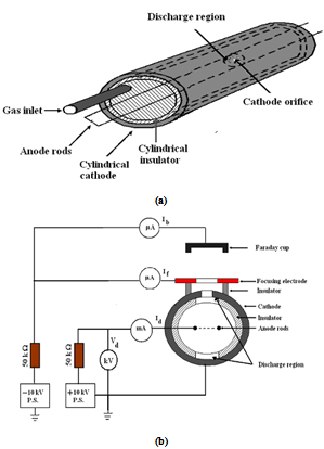 | Figure 1. Modified saddle field ion source and its electrical circuit |
4. Experimental Investigations and Results
- Firstly, the ion source was operated for a period of time to outgas the different parts before taking any measurements. Fig. 2 shows the relation between discharge current, Id, in mA versus the discharge voltage, Vd, in kV at different pressures using nitrogen gas. It is clear that the discharge current increases by increasing the discharge voltage and the discharge voltage starts at lower potential in case of high pressure than that in case of low pressure.Fig.3 shows the ion beam current versus the discharge current for different pressures at the optimum distance between the two anode rods and the cathode equals 6 mm and the discharge region equals 5 mm without using focusing voltage Vf = 0. It is seen that, maximum ion beam current of 100 µA can be obtained at a discharge current of 1.5 mA and a pressure of 8x10⁻⁴ mbar.
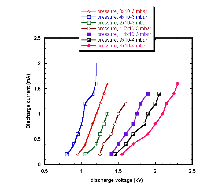 | Figure 2. discharge current versus the discharge voltage at different pressures using nitrogen gas at distance between the two anode rods and cathode = 6 mm, discharge region = 5 mm |
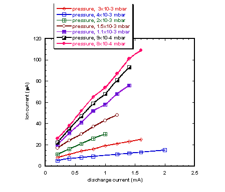 | Figure 3. Ion beam current versus the discharge current at different pressures using nitrogen gas at distance between the two anode rods and cathode = 6 mm, discharge region = 5 mm and Vf = 0 kV |
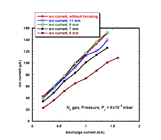 | Figure 8. Relation between the discharge current and ion beam current at Pressure Pr = 8x10⁻⁴ mbar using nitrogen gas at distance between two anode rods= 6 mm, discharge region = 5 mm |
5. Conclusions
- From this study, it is clear that this source is characterized by: (1) simple, compact and with well collimated ion beam, (2) large ion currents could be produced. Different ring electrodes with different exit hole diameters (5, 7, 9 and 11 mm) were used as focusing electrodes. The optimum diameter for the focusing electrode hole was found to be 9 mm where maximum ion beam current can be obtained. It was found that at 9 mm diameter, focusing voltage = - 3 kv, and Pressure Pr = 8x10⁻⁴ mbar using nitrogen gas at distance between the two anode rods= 6 mm, discharge region = 5 mm, ion beam current was reached to 243 µA. These advantages point to the possible application of the saddle field ion source as an effective long lived ion source.
ACKNOWLEDGMENTS
- The authors thank the Egyptian Atomic Energy Authority, Egypt for financial support and for Mr. B. Ali for his contribution during the investigation of this work.
 Abstract
 Reference
 Full-Text PDF
 Full-Text HTML