Maryam Ghasemloo , Mahmood Ghoranneviss, Ahmad Sala
Plasma Physics Research Center, Science and Research Branch, Islamic Azad University, Tehran, P.O.Box: 14665-678, Iran
Correspondence to: Maryam Ghasemloo , Plasma Physics Research Center, Science and Research Branch, Islamic Azad University, Tehran, P.O.Box: 14665-678, Iran.
| Email: |  |
Copyright © 2012 Scientific & Academic Publishing. All Rights Reserved.
Abstract
In this paper, The first results of the movable emissive limiter biasing experiments performed on the IR-T1 Tokamak are presented. For this purpose, a moveable emissive limiter system was designed, constructed, and installed on the IR-T1 Tokamak. The emissive biased limiter is positioned at r/a=1.05, and the biased voltage which is varied from -350 to 350 V applied between the head of emissive limiter and vacuum chamber. Then, the plasma current, safety factor, poloidal beta and plasma resistance in the absence and presence of the emissive biased limiter in negative polarity were measured and results were compared with the cold limiter biasing in negative polarity. Much more plasma parameters such as the magneto hydrodynamics instability and plasma energy confinement time are determined by using these parameters. Diamagnetic loops and loop voltage can be utilized in measurements of the plasma poloidal beta and plasma resistance. Result are compared and discussed.
Keywords:
Tokamak, Emissive Limiter Bias, Safety Factor, Poloidal Beta
1. Introduction
Electrostatic polarization of the plasma edge has the capacity initiate an improved energy and particle confinement regime by applying voltage between the head of the limiter and the vessel, so a radial electric field is produced and the consequent force initiates sheared flows which has a suffocating effect on turbulence. The development of the E× B shear stabilization model, which is utilized to define the formation of transport barriers in magnetic confinement devices, leads to the improvement of the confinement.The basic physics to be used in transport reduction is the impact of E×B velocity shear on the growth, radial extent, and phase correlation of turbulence eddies in the plasma. However, it seems that the E×B velocity shears has an effect on force balance equation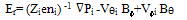 | (1) |
The above equation implies that there is a connection between Er, the cross field heat and practical transport (ΔPi), cross field angular momentum transport (Vɸi) and poloidal flow (Vϴi), since sheared E× B flow also affect turbulence and transport[1]. The control of the shear layer is a crucial tool to modify transport in Tokamak[2-5]. According to experiments done in other Tokamak for negative bias, no significant modification of either the global or the edge plasma parameters were observed, simply because the current drawn by the limiter was low. Consequently, an emissive limiter has to be used to develop a larger current necessary to modify confinement at negative applied voltage[6]. Measurements of poloidal beta  and edge safety factor qa are important for Tokamak plasma research. Much of the plasma information such as plasma energy, plasma pressure, plasma confinement time and magneto hydrodynamics (MHD) instability can be deduced using these two parameters.
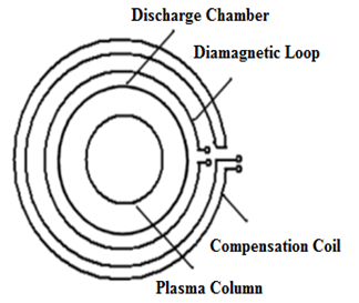 | Figure 1. Diamagnetic and Compensating loops |
The relationship between the poloidal beta and the diamagnetic flux  is determined as[7,8,11]:
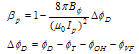 | (2) |
Where Ip is the plasma current, and  is the toroidal magnetic field,
  is the diamagnetic signal that is measured by diamagnetic loop as shown in Figure 1. Furthermore,
  is the toroidal flux due to the toroidal magnetic field that is measured by a compensating loop as illustrate in Figure 1.Safety factor q is one of the key parameters describing the stability of the plasma in Tokamak. The meaning of this dimensionless parameter is the number of toroidal turns it which takes a magnetic field line to make a single full poloidal turn. For Tokamak with circular cross-section, it is given by following formula:
 | (3) |
Where r is radial coordinate along the minor radius, R is major radius, BT is toroidal magnetic field and  is poloidal magnetic field. As q has clearly a radial dependence, it is convenient to express its value at the boundary of the plasma confinement region called separatrix using the measured quantities as BT and plasma current Ip
 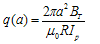 | (4) |
Assuming the constant R and BT, the radial profile of q inside the plasma confinement region is given only by radius r and radial profile of  [9,10].
2. Experimental Setup
IR-T1 Tokamak is a small circular cross-section research Tokamak (R=0.45m, a vessel=0.15m) which has two stainless steel grounded fully poloidal limiters with a limiter= 0.125m, located at Plasma Physics Research Canter (PPRC). The maximum achieved plasma current is 35KA, toroidal magnetic field induction BT= 0.8T, the discharge time is 35ms, the mean electron density is 1.5×10¹⁹m-3. The experiments were performed in hydrogen. The average pressure before discharge was 2.2×10⁻⁵Torr. In order to do the experiments, an emissive biased limiter was designed and fabricated, the head of which made of an arc- shaped stainless steel with the radius of 12.5cm and the thickness, width and the height are 4mm, 20mm and 30mm, respectively. There is an element inside the limiter which can evenly raise the temperature of limiter using a separate DC power supply. The head of emissive limiter and its horizontal position inside the vessel have been illustrated in the Figure2.The position of emissive biased limiter is r\a=1.05. The applied biased voltage between head of this limiter and the vacuum chamber is in the range of -350 to 350V and the bias current is between 10 and 40A, the current of limiter heating is 5A.
3. Experimental Results and Discussion
In this contribution we reported mainly the effect of the emissive biased limiter with negative polarity on the plasma current, poloidal beta , safety factor and plasma resistance. Results compared with the cold limiter biasing in negative polarity. Figure 3 illustrates the time evolution of the plasma current and the current of biased limiter.
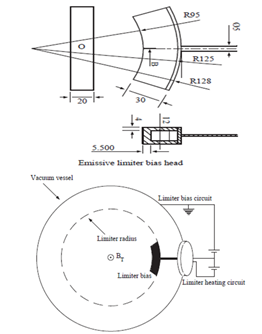 | Figure 2. Top: the size of head of emissive limiter, below: schematic illustration of emissive limiter position inside the vessel |
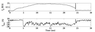 | Figure 3. Time evolution of the plasma current and the biased limiter current |
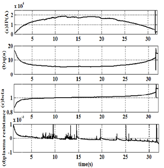
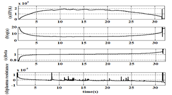 | Figure 4. (a) Time evolution of the plasma current, (b) safety factor, (c) the poloidal beta βP, (d) plasma resistance in absence of the biasing. |
In Figure 4 the time evolution of the plasma current, safety factor, poloidal beta βP, and plasma resistance in absence of the biasing have been calculated and are shown. In Figures 5 and 6, the time evolution of the plasma current, safety factor, the poloidal beta βP, and plasma resistance in the presence of the cold biased limiter and emissive biased limiter for negative applied voltage Vbias= - 350V were presented respectively. In our experiments the bias voltage is applied at 12.5 ms.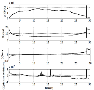 | Figure 5. (a) Time evolution of the plasma current, (b)safety factor, (c) poloidal beta βP, (d) plasma resistance in presence of negative cold biased limiter for r\a=1.05 . |
 | Figure 6. (a) Time evolution of the plasma current, (b)safety factor, (c)the poloidal beta , (d)plasma resistance in presence of the negative emissive biased limiter for r\a=1.05 |
4. Summary and Conclutions
The first results of the moveable emissive limiter biasing experiments performed on the IR-T1 Tokamak are presented. For this purpose, a moveable emissive limiter system was designed, constructed, and installed on the IR-T1 Tokamak. Then, the negative voltage applied to an emissive limiter inserted inside the Tokamak fixed limiter and the plasma current, safety factor, poloidal beta β and plasma resistance in absence and presence of emissive limiter biased for negative polarity, were measured. Results compared with the cold limiter biasing in negative polarity. The position of emissive biased limiter is r\a=1.05.As we expected and the results of IR-T1 Tokamak show, in emissive negative polarity, time duration of plasma current increased. Besides, plasma current in this polarity is more uniform compared to no bias polarity.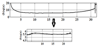 | Figure 7. expanded of safety factor profile in absence of the biasing |
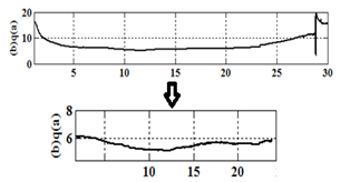 | Figure 8. expanded of safety factor profile for cold limiter biased in negative polarity |
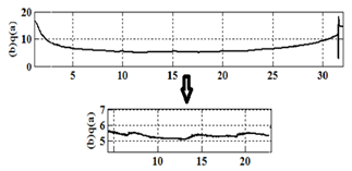 | Figure 9. expanded of safety factor profile for emissive limiter biased in negative polarity |
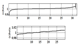 | Figure 10. expanded of beta profile in absence of the biasing |
 | Figure 11. expanded of beta profile for cold limiter biased in negative polarity |
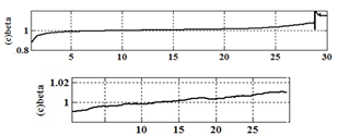
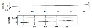 | Figure 12. expanded of beta profile for emissive limiter biased in negative polarity |
Figures 10-11-12 that are related to expanded of β profile in flat region of plasma current, for no bias, cold negative, emissive negative polarities, respectively, show that cold and emissive limiter biasing for negative polarity have no effect on it.Figures 13-14-15 that are related to expanded of plasma resistance (R) in flat region of plasma current, for no bias, cold negative, emissive negative polarities, respectively, show that amplitude and fluctuation of this parameter, decreased in cold negative polarity and increased in emissive negative polarity compared to no bias polarity.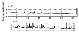 | Figure 13. expanded of plasma resistance in absence of the biasing |
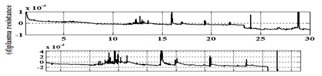 | Figure 14. expanded of plasma resistance for cold limiter biased in negative polarity |
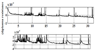 | Figure 15. expanded of plasma resistance for emissive limiter biased in negative polarity |
References
| [1] | K. H. Burrell, Phys. Plasma. vol.4, pp.1499-1518. 1997. |
| [2] | C. Silva et al, 17th IAEA fusion energy conference, EX/P1-10, Lyon, Oct 2002. |
| [3] | R .J. Taylor et al., Phys. Rev. Lett.vol.63, pp.2365, 1989. |
| [4] | R. Weynants, G. Van Oost, Plasma Phys. Control Fusion, vol 35, B177, 1993. |
| [5] | R.Weynants et al., Nucl. Fusion, vol 32, pp.837, 1992. |
| [6] | P. Balan et al., Nucl. Fusion., vol.44, pp.799-810, 2004. |
| [7] | L. E. Zakharov, V. D.shafranov, Equilibrium of toroidal plasma with noncircular cross section, Sov. Phys. Tech. Phys 18(2), pp.151-156, 1973. |
| [8] | I. H. Hutchinson, principles of plasma diagnostics (Cambridge University Press, Cambridge, pp.10-33, 1987. |
| [9] | K. Kovarik, I .Duran. ” Measurement of safety factor using Hall probes on CASTOR Tokamak”, Czechoslovak Journal of Physics, Vol.56. 2006. |
| [10] | A. Salar Elahi, M. Ghoranneviss, M.Emami, A. Rahimi Rad. “Theoretical and experimental Approach in Poloidal Beta and Internal Inductance Measurement on IR-T1 Tokamak”, J Fusion Energ, 28, pp.346-349, 2009. |
| [11] | A. Salar Elahi, M. Ghoranneviss, “Experimental Study of Effects of the Internal Inductance on the Energy Confinement Time on IR-T1 Tokamak”. J Fusion Energ, 29, pp.36-40, 2010. |
 Abstract
 Reference
 Full-Text PDF
 Full-Text HTML