Ahmad Salar Elahi , Mahmood Ghoranneviss
Plasma Physics Research Center, Science and Research Branch, Islamic Azad University, Tehran, Iran
Correspondence to: Ahmad Salar Elahi , Plasma Physics Research Center, Science and Research Branch, Islamic Azad University, Tehran, Iran.
| Email: |  |
Copyright © 2012 Scientific & Academic Publishing. All Rights Reserved.
Abstract
Determinations of poloidal beta, internal inductance, plasma energy, plasma pressure, plasma temperature, plasma resistance, plasma effective atomic number, and plasma energy confinement time are essential for tokamak plasma experiments. In this paper an experimental methods especially based on diamagnetic loop (toroidal flux loop) for measurements of these parameters are presented. For this purposes a diamagnetic loop with its compensation coil and also an array of magnetic probes designed, constructed, and installed on outer surface of the IR-T1 tokamak. Also in this work we obtained the Shafranov parameter, plasma current, plasma voltage, and the plasma density from the magnetic probe, Rogowski coil, poloidal flux loop, and the Langmuir probe measurements, respectively.
Keywords:
Tokamak, Plasma Parameters, Diamagnetic Loop, Magnetic Probe
Cite this paper:
Ahmad Salar Elahi , Mahmood Ghoranneviss , "Simultaneous Simple Measurements of Tokamak Plasma Parameters Especially Based on Plasma Diamagnetic Effect", Journal of Nuclear and Particle Physics, Vol. 1 No. 1, 2011, pp. 10-15. doi: 10.5923/j.jnpp.20110101.03.
1. Introduction
Determinations of the poloidal beta, internal inductance, plasma energy, plasma pressure, plasma temperature, plasma resistance, plasma effective atomic number, and energy confinement time are essential for tokamak experiments and optimized operation. Also some of the plasma information can be deduced from these parameters, such as plasma toroidal current profile, and magnetohydrodynamics (MHD) instabilities.Magnetic diagnostics, in particular diamagnetic loop (toroidal flux loop) are commonly used in tokamaks to measure the variation of toroidal flux induced by the plasma. On the other hand, the magnetic fields distribution outside the plasma provides the measurement of the combination of poloidal Beta and internal inductance  , via the Shafranov parameter Λ, and also Langmuir probe measurement provides the value of plasma density. Then measurement of Λ from the magnetic probe and poloidal Beta from diamagnetic loop gives a value of internal inductance. Also measurement of plasma energy with diamagnetic loop and measurement of plasma density with Langmuir probe gives a value of plasma temperature. Energy confinement time, plasma resistance, and also the plasma pressure are also can be determined from diamagnetic loop [1-8]. In this paper we presented experimental magneticdiagnostic methods on IR-T1, which it is a small, low beta and large aspect ratio tokamak with a circular cross section (see Table 1). Brief approach for measurement of asymmetry factor by the discrete magnetic probes will present in section 2. Diamagnetic loop method for measurements of the eight of the basic plasma parameters will present in section 3. Details of design and construction of magnetic probe and diamagnetic loop will present in section 4. Experimental results will discuss in section 5. Summary is also present in section 6.
| Table 1. Main Parameters of the IR-T1 Tokamak. |
| | Parameters | Value | | Major Radius | 45 cm | | Minor Radius | 12.5 cm | | Toroidal Field |

1.0 T | | Plasma Current |

40 kA | | Discharge Duration |

35 ms | | Electron Density | 0.7-1.51013cm-3 |
|
|
2. Determination of the Asymmetry Factor (Shafranov Parameter) Using the Magnetic Probes
Poloidal Beta and internal inductance relate to the distribution of magnetic fields around the plasma current. Therefore, those can be written in terms of the tangential and normal components of the magnetic field on the contour (see Fig. (3)). Distributions of the tangential and normal magnetic fields are also can be written in the first order of the inverse aspect ratio as follows, respectively [2,5]: 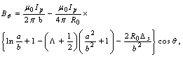 | (1) |
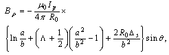 where R0 is the major radius of the vacuum vessel, Δs is the Shafranov shift, Ip is the plasma current, α and b are the minor plasma radius and minor chamber radius respectively and li is the plasma internal inductance. These equations accurate for low beta plasma, large aspect ratio, and circular cross section tokamaks as IR-T1, and where:
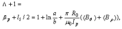 | (2) |
where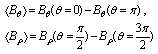 We can obtain poloidal and normal components of the magnetic field from the output signals of the magnetic probes after compensation and integration. Therefore we can be to calculate the Shafranov parameter from the Eq. (2). The compensation done by fields discharge without plasma and receives output signals of the magnetic probes and subtract those from total output signals from the probes. Moreover we used the Rogowski coil, Langmuir probe, and the poloidal flux loop for measurements of the plasma current, plasma density, and the plasma voltage, respectively, but only we will present their data and used them in our measurements.
3. Measurements of Eight of the Plasma Parameters using the Diamagnetic Loop (Toroidal Flux Loop)
Diamagnetic loop measures the toroidal diamagnetic flux for the purposes of measurements of the plasma parameters e.g. poloidal beta and thermal energy of the plasma. The toroidal flux that produced by the plasma is related to the total perpendicular thermal energy of the plasma. This diamagnetic flux is usually measured with the diamagnetic loop. It is usually a single wire which circling the plasma column either inside or outside of the plasma vacuum chamber. Intrinsically this loop will also pickup the toroidal magnetic flux from the toroidal field coil and any current circulating in the poloidal plane, in particular toroidal field coil current, eddy currents in the conducting vacuum chamber induced during transient changes in the plasma energy and plasma current. In other words, the diamagnetic loop consist of a simple loop that links the plasma column, ideally located in a poloidal direction in order to minimize detecting the poloidal field. In cases of the ohmically heated tokamaks (low beta) where the plasma energy density is small compared to the energy density of the magnetic field, the change in the total toroidal magnetic flux is small. Therefore a reference signal equal to the vacuum toroidal magnetic flux is usually subtracted from it, giving a net toroidal flux equal to the diamagnetic flux  produced by the circular plasma. Relation between the diamagnetic flux and the poloidal beta derived from simplified equilibrium relation [3,6]:
 | (3) |
where  and
and ,and where
 is the toroidal magnetic field in the absence of the plasma which can be obtained by the magnetic probe,
  is the plasma current which can be obtained by the rogowski coil,
  is the toroidal flux because of toroidal field coils,
  and
and  are the passing flux through loop due to possible misalignment between ohmic field and vertical field and the diamagnetic loop and
  is the toroidal field due to eddy current on the vacuum chamber. These fluxes can be compensated either with compensation coil or fields discharge without plasma. It must be noted that compensating coil for diamagnetic loop is wrapped out of the plasma current, and only the toroidal flux (which is induced by the change of toroidal field coil current when plasma discharges) can be received (see Fig. (2) and Fig. (3)). As shown in Eq. (3) the diamagnetic loop signal contains two parts, plasma diamagnetic flux and the vacuum toroidal flux. So the diamagnetic flux
  caused by plasma current can be measured from the diamagnetic loop and compensating coil using subtraction. Therefore combination of the magnetic probe and diamagnetic loop measurements give us the value of the internal inductance:
 | (4) |
If we want to have a determination of the volume averaged plasma kinetic pressure , it is can be measured directly from the definition of the poloidal Beta:
 | (5) |
where  is the plasma minor radius.For measurement of the plasma thermal energy we start from the plasma state equation:
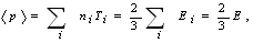 | (6) |
where subscript  indicate the plasma species
 , and
, and  indicate the plasma thermal energy density, therefore the plasma thermal energy
 , and also plasma temperature is obtained:
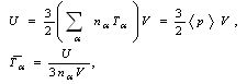 | (7) |
where  is the plasma volume. If we have the quasi neutral plasma density from the Langmuir probe measurements, then we can find the plasma averaged temperature from Eq. (7).The plasma specific resistance in the steady state plasma is can be written as:
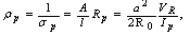 | (8) |
where  is the plasma conductivity,
  is the plasma resistance, and
  is the resistive component of the loop voltage (poloidal flux loop). Moreover for determining the plasma effective atomic number we use the Spitzer relation for plasma conductivity[6]:
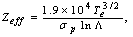 | (9) |
where  is the Coulomb logarithm.But most important of these measurements is the determination of the plasma thermal energy confinement time which defined by equation:
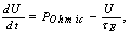 | (10) |
where  is the plasma energy confinement time, and
  is the rate of input heating power. Rearranging Eq. (10), the ohmic heating power is:
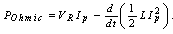 | (11) |
If the plasma is in thermal equilibrium ( , and
, and ), then from Eqs. (7), (10) we have:
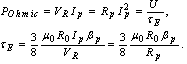 | (12) |
Also if  is not negligible, then from Eqs. (7), (10) we have:
 | (13) |
In the flat region of the tokamak plasma current, time variations is very small and Eq. (12) is indefeasible. Therefore according to above discussion we can find eight of the mentioned parameters by the diamagnetic loop and with helping the magnetic probe, Rogowski coil, poloidal flux loop, and Langmuir probe (see Fig. (1)). Experimental results for determinations of these parameters will present in section 5.  | Figure 1. Schematic Representation of the Our Measurements Procedure |
4. Design and Construction of the Magnetic Probe and Diamagnetic Loop
In general the magnetic sensors (magnetic probe or diamagnetic loop) works based on Faraday’s law and measures component(s) of the local magnetic fields or magnetic fluxes for use in plasma control, equilibrium reconstruction and detection of plasma energy, poloidal beta and MHD instabilities.Magnetic probe consists of a coil in solenoidal form, which whose dimensions are small compared to the gradient scale length of the magnetic field. A total magnetic flux passed through such a coil is , where n is the number of turns of coil, A is the average area of cross section of coil, and B is the local magnetic field parallel to the coil axis (see Fig. (2)).The output signal from the magnetic probe or from the diamagnetic loop is:
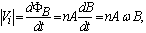 | (14) |
where  is the frequency of the fluctuations of the magnetic field, the average area of the probe is determined by assumption that the diameter of the coil is equal to mean value
 , thus:
 | Figure 2. Schematic Representation of the Magnetic Probe |
We selected the frequency response of the magnetic probe, 22 kHz for this work and multi-purposes works for future. Therefore we designed the probe in this frequency region. Thus first input value for designing the magnetic probe is the frequency response; the second input value is the sensitivity of the magnetic probe, and third relation is the ohm law. The coil resistance, coil inductance, winding turns of coil, length of coil, and coil radius, are the five interrelated desired parameters. Because of parameters multiplicity and relation limitation, two of the five parameters must be obtained from the three basic relations mentioned above. The first basic relation which mentioned is the frequency response of coil: | (15) |
where F is a constant which depending on the ratio of the coil length  to its radius
  (for
(for ) the second relation is the famous ohm law:
 | (16) |
where  and
and  are the length of total wire which used, and cross section area of the wire. The third relation is the sensitivity of the magnetic probe:
 | (17) |
Therefore, we were inserted two desired sensitivity and frequency response values and other three values were obtained from above three relations. In order to calibration of the magnetic probe, it must be insert into a homogeneous magnetic field of known amplitude  and frequency
  then effective value of the
  will obtain. For this purpose we insert the magnetic probe inside the Helmholtz coil.The homogeneous magnetic field between the Helmholtz coils is:
 | (18) |
where 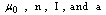 are respectively, the permeability of the free space, number of turns, current and radius of the Helmholtz coils.In the IR-T1 tokamak, an array of four magnetic probes were designed, two magnetic probes were installed on the circular contour
  of the radius
  in angles of
  and
and  to detect the tangential component of the magnetic field
  and two magnetic probes are also installed above,
  , and below,
  , to detect the normal component of the magnetic field
 , as shown in Fig. (3).
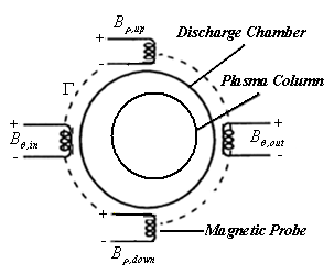 | Figure 3. Positions of the Four Magnetic Probes on the Outer Surface of the IR-T1 Tokamak Chamber |
 | Figure 4. Positions of the Diamagnetic Loop with its Compensation Coil on the Outer Surface of the IR-T1 Tokamak Chamber |
After measurements  and
and  from magnetic probes, and
  from rogowski coil and substituting them in to Eq. (2) Shafranov parameter were obtained. Design parameters of the magnetic pickup coils present in Table 2. Diamagnetic loop and its compensating coil also were constructed and installed on the IR-T1 tokamak (see Fig. (4)). Diamagnetic loop characteristics are also shown in Table 2.
| Table 2. Design Parameters of the Magnetic Probes and Diamagnetic Loop |
| | Parameters | Magnetic Probe | Diamagnetic Loop | | R (Resistivity) | 33

| 100

| | L (Inductance) | 1.5mH | 20mH | | n (Turns) | 500 | 170 | | S (Sensitivity) | 0.7mV/G | 0.5V/G | | f (Frequency Response) | 22kHz | 5kHz | Effective

| 0.022

| 16

| | d (Wire Diameter) | 0.1mm | 0.2mm |

(Coil Average Radius) | 3mm | 175mm |
|
|
5. Experimental Results and Comparison between Them
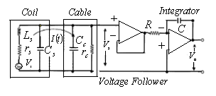
We used the circuit as shown in Figures (4) and (5), for the measurement of induced voltage  in the magnetic probes and in the diamagnetic loop:
 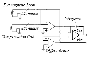 | Figure 5. Electric Circuit for Diamagnetic Loop and its Compensation Coil |
 | Figure 6. Electric Circuit for Magnetic Probe |
As shown in the Fig. (6),  is the current in the magnetic probe circuit and
  is the coaxial cable output signal. The application of Kirchhoff’s voltage law for this circuit yields the following equation:
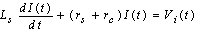 | (19) |
where  is the probe resistivity and
  the cable resistivity and
  probe self-inductance. This expression is valid if the frequency of the interest signal
 , is much smaller than the natural oscillation frequency of the coil (resonant frequency)
  . In this case, and since
  is smaller than
 , the capacitive reactance
  is greater than the inductive reactance
 , such that for practical reasons the sum of the capacitances can be neglected. These conditions are satisfied in the measurement system composed of the magnetic probes or diamagnetic loop. From the circuit of Figure (6), we have:
 | (20) |
Also from the circuit of Figure (5) we have: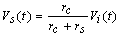 | (21) |
So, the integrator output  of Fig. (6), is given by:
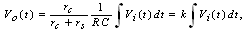 | (22) |
where,  is the integrator time constant and Eq. (22) is the integrated output of the probe signal. Moreover
  is the inductive voltage supplied by each one of the magnetic pickup coils or diamagnetic loop, where installed around the vacuum chamber of the IR-T1 tokamak.In the case of the magnetic pickup coils the magnetic field can be obtained from:
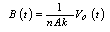 | (23) |
And in the case of diamagnetic loop, diamagnetic flux can be obtained from: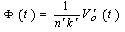 | (24) |
Results present in Tables (3), (4) and Figs. (7), (8), (9), (10).| Table 3. Plasma Parameters at t=15ms in Target Shot which Determined based on Rogowski Coil, Flux Loop, Langmuir Probe, and Magnetic Probes |
| | Plasma Parameters | Values | | Total Discharge Duration |

| | Plasma Current |

| | Input Heating Power |

| | Plasma Density |

| | Toroidal Field |

| | Loop Voltage |

| Shafranov Parameter

|

|
|
|
| Table 4. Eight of the Plasma Basic Parameters at t=15ms in Target Shot which Determined based on Diamagnetic Loop |
| | Plasma Parameters | Value | | Poloidal Beta |

| | Internal Inductance |

| | Plasma Averaged Pressure |

| | Plasma Averaged Energy |

| | Plasma Particles Temperature |

| | Plasma Ohmic Resistance |

| | Effective Atomic number |

| | Plasma Energy confinement Time |

|
|
|
 | Figure 7. Diamagnetic Loop Method for Measurement of Poloidal Beta: (a) Plasma Current, (b) Toroidal Magnetic Field, (c) Plasma Diamagnetic Flux, and (d) Poloidal Beta along the Plasma Current |
 | Figure 8. Combination of Diamagnetic Loop and Magnetic Probes Results: (a) Plasma Current, (b) Internal Inductance obtained by Subtraction of Poloidal Beta (c) from Shafranov Parameter (d) |
 | Figure 9. Diamagnetic Loop Measurements Results: (a) Plasma Current, (b) Plasma Averaged Energy, (c) Plasma Energy Confinement Time, (d) Plasma Particles Averaged Temperature |
 | Figure 10. Diamagnetic Loop Measurements Results: (a) Plasma Current, (b) Plasma Pressure, (c) Plasma Effective Atomic Number, (d) Plasma Resistance |
6. Summary
Diamagnetic loop with its compensation coil and also an array of magnetic probes have been designed, constructed, and installed on the IR-T1 tokamak. The poloidal and radial components of the magnetic fields and also diamagnetic flux signal obtained. Then from value of  which obtained from the magnetic probes, and the poloidal Beta which obtained from the diamagnetic loop, the value of internal inductance
  were obtained. And also by measurement of plasma energy with diamagnetic loop and by measurement of plasma density with Langmuir probe the value of plasma temperature were obtained. Moreover, plasma pressure, plasma resistance, plasma effective atomic number, and plasma energy confinement time is also determined from the flux loop and diamagnetic loop.
References
| [1] | J. Wesson, Tokamaks, (Clarendon, Oxford, 1997) |
| [2] | V. S. Mukhovatov and V. D. Shafranov: Nucl. Fusion 11, (1971), 605 |
| [3] | E. J. Strait and et al., Fusion Science and Technology 53, 2008, pp. 304-330 |
| [4] | L.E. Zakharov, V.D. Shafranov, Sov. Phys. Tech. Phys. 18 (2) (1973) 151-156 |
| [5] | H. Niomiya and N. Suzuki, Japanese Journal of Applied Physics 21 (9), September, 1982, pp. 1323-1327 |
| [6] | I. H. Hutchinson, Principles of Plasma Diagnostics, Cambridge University Press, Cambridge, 1987, pp. 10–33 |
| [7] | A. Salar Elahi and et al., J. Fusion Energy 28 (4), (2009) |
| [8] | M. Emami, M. Ghoranneviss, A. Salar Elahi and et al., J. Plasma Physics 76 (1), (2009) |
 Abstract
 Reference
 Full-Text PDF
 Full-Text HTML