Dengpan Zhang, Xianjin Liu, Yibo Zheng, Xian Zhao
School of Mechanical and Power Engineering, Henan Polytechnic University, Jiaozuo, China
Correspondence to: Xianjin Liu, School of Mechanical and Power Engineering, Henan Polytechnic University, Jiaozuo, China.
| Email: |  |
Copyright © 2023 The Author(s). Published by Scientific & Academic Publishing.
This work is licensed under the Creative Commons Attribution International License (CC BY).
http://creativecommons.org/licenses/by/4.0/

Abstract
As a commonly used transmission device, cylindrical gear system is widely used in the fields of mechanical manufacturing and industrial production. However, due to the problems of low transmission efficiency, high noise, and severe wear in the gear system, optimization design is needed to improve its performance. This article combines modern computer-aided design technology to establish a three-dimensional model of the gear system, and introduces various parameters under excitation, including manufacturing errors, elastic deformation of shafts and bearings, to design the cylindrical gear transmission system. The performance of the modified gear transmission system has been significantly improved under different excitation effects, with a reduction of 44% in peak transmission error and 52.5% in peak transmission acceleration, respectively. At the same time, the normal force distribution on the modified tooth surface is relatively uniform, and the service life of the system has been extended. This study indicates that introducing multiple excitation effects for shape modification design in the optimization design of cylindrical gear systems can effectively improve their performance. The research results have important practical significance for improving the transmission efficiency and stability of gear systems and guiding the design and manufacturing of gear transmission systems.
Keywords:
Cylindrical gear, Dynamic motivation, KISSsoft, Optimize modification
Cite this paper: Dengpan Zhang, Xianjin Liu, Yibo Zheng, Xian Zhao, Research on the Modification Design of Cylindrical Gear System under Various Excitations, Journal of Mechanical Engineering and Automation, Vol. 12 No. 2, 2023, pp. 29-35. doi: 10.5923/j.jmea.20231202.01.
1. Introduction
As an important component of mechanical transmission, cylindrical gear system plays an important role in industrial production and mechanical manufacturing. However, the low transmission efficiency, high noise, and severe wear of cylindrical gear systems limit their performance in practical applications. In order to improve the performance of cylindrical gear systems, many researchers have conducted relevant research and exploration. In the research of gear modification, the main methods used are tooth profile modification, tooth lead modification, and a combination of tooth profile and tooth lead modification [1-3]. Hajjaj A Z [4] studied the stability and modification optimization methods of gear pairs. Tang Z [5] established a parameterized three-dimensional model for the multi-stage gear transmission system of new energy vehicles and developed an analysis method for predicting the stability of gear pairs. Han G [6] proposed a comprehensive gear modification method and established a multi-objective optimization model for tooth surface modification parameters by coupling the NSGA-II algorithm with the efficient Loaded Tooth Contact Analysis (LTCA) model. Wang Xinxing [7] achieved micro modification optimization schemes for composite gears such as tooth lead modification, involute modification, and tooth profile modification through genetic algorithms, and conducted remodeling, simulation, and experimental testing. In addition, some scholars have considered the influence of elastohydrodynamic lubrication (EHL) and proposed a new method to calculate the maximum modification amount using the meshing stiffness of gear elastohydrodynamic friction pairs [8]. In terms of profile modification optimization, some scholars have used virtual simulation verification methods to carry out helical profile modification optimization with typical external meshing spur gears as the research object [9], while others have combined tooth profile modification methods and tooth lead modification methods to optimize small solar gears [10]. Yan Guoping [11] obtained a new involute equation by applying the Walker modification method, and parameterized modeling of gear pairs based on the APDL program, explicit dynamic simulations were conducted on three types of modified curve gear transmissions during dynamic meshing to obtain the contact stress values during gear tooth meshing.These research results provide important theoretical basis and technical support for the optimization design and fault diagnosis of gear transmission systems. However, there is relatively little research on the modification design of gears that considers the effects of multiple displacement excitations. This article establishes a primary gear transmission system consisting of gear pairs, transmission shafts, and bearings using KISSsoft software, taking into account manufacturing errors and elastic deformation of shafts and bearings. Compared to traditional finite element simulation software, KISSsoft can more conveniently modify the relevant parameters of the gear system.
2. Displacement Excitation of Gear Systems
In gear transmission, there are two forms of dynamic excitation: internal and external. Among them, external excitation is the external interference received by the system, including the torque of the power source, the impedance of the load, impedance torque, etc. The calculation method of its external excitation is consistent with ordinary mechanical systems. Internal excitation is an important characteristic that distinguishes gear transmission from ordinary mechanical systems, mainly including error excitation, stiffness excitation, and meshing impact excitation caused by machining errors and deformation during the transmission process. The focus of this article is to analyze the internal excitation of the gear system.
2.1. Excitation Generated by Manufacturing Errors
Error excitation is caused by factors such as gear machining and assembly. From the perspective of gear dynamics, the above machining errors are essentially a displacement type dynamic excitation caused by the deviation between the actual machining tooth surface and the ideal tooth surface. The assembly error causes the tooth surface load to deviate, resulting in vibration excitation.Generally speaking, the machining error of gears is usually decomposed into two forms: pitch error and tooth profile error, as shown in Figure 1. This article provides a detailed analysis of the generation mechanism of tooth profile error excitation through examples. As shown in Figure 2, tooth A is a gear tooth with an ideal involute tooth profile, and tooth A' is a gear tooth with machining errors, and the error is amplified here. According to the meshing principle of involute gears, the original driving gear tooth A and the driven gear tooth A' were correctly meshed at point P, but due to tooth profile errors, tooth A entered meshing early at point P', which resulted in a change in instantaneous transmission ratio and affected the smoothness of the gear system transmission, causing a significant impact, resulting in vibration and noise. In gear transmission, as the error changes over time, this excitation constitutes a displacement excitation in gear transmission.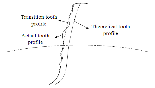 | Figure 1. Definition of machining error |
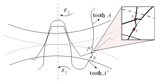 | Figure 2. Schematic diagram of error excitation |
Regarding the representation method of machining error, traditional methods usually use empirical formulas to represent machining error in the form of a sine function, in order to better describe its characteristics, as shown in equation (1).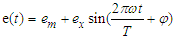 | (1) |
In the formula,  is the gear machining error;
  is the constant value of gear machining error;
  is the amplitude of gear machining error;
  is the meshing period of the gear pair;
  is the meshing frequency;
  is the initial phase angle.
2.2. Deformation of Transmission Components
In the process of gear system transmission, due to the fact that gears, shafts, and bearings are all elastic bodies, the contact between various components will cause deformation. Most scholars often overlook the deformation of shafts and bearings when conducting gear dynamics research. The bending deformation of the shaft is shown in Figure 3.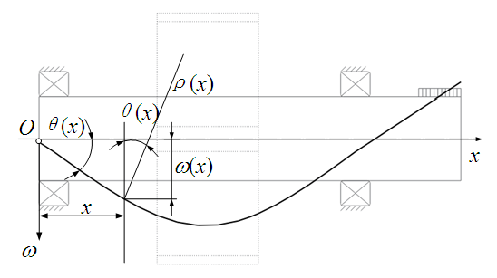 | Figure 3. Bending deformation of the shaft |
Simplify the axis as a beam structure, and according to material mechanics, the deflection curve equation of the axis is: | (2) |
In the equation,  is the line displacement of the cross-section centroid along the initial direction.The relationship between rotation angle and deflection curve equation is:
 | (3) |
In the formula,  is the angle at which the cross-section rotates around the neutral axis;
  is the distance from the deformation point in the axis direction to the origin.Due to the relatively small deformation angle of the shaft, when the shaft undergoes small deformation, the above equation can be changed to:
 | (4) |
The approximate differential equation calculation formula for the small deformation deflection curve of the shaft is: | (5) |
In the formula, M is the bending moment; E is the elastic modulus; I is the moment of inertia.The elastic deformation of bearing and the deformation of tooth surface are calculated by Hertz contact theory. Based on the basic principle of classical mechanics, this theory describes the relationship between physical quantities such as stress, strain and elastic deformation between contact surfaces, and obtains the relationship between contact pressure and elastic deformation between contact surfaces.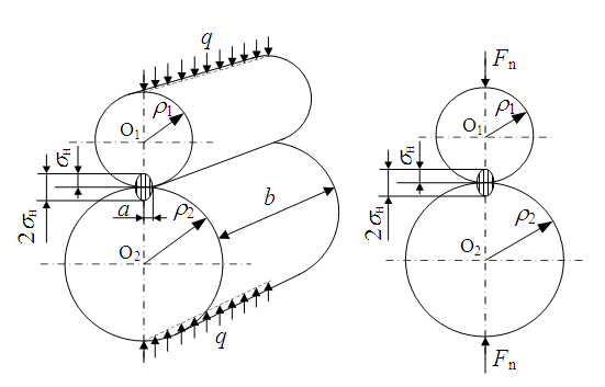 | Figure 4. Simplified diagram of the hertz contact stress calculation |
As shown in Figures 4, when two cylinders are subjected to a unit width load q along the contact line, contact stress will occur. At the initial line contact, the two cylinders come into contact along the busbar. After being loaded, due to the elastic deformation of the material, the contact line becomes a contact zone, and the distribution of contact stress is uneven. The maximum compressive stress on the initial contact line is recorded as  . According to the Hertz formula, the maximum contact stress can be derived as:
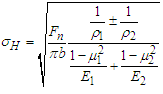 | (6) |
In the formula,  is the maximum contact stress;
  is the load per unit width;
  is the concentrated load acting on two cylinders, that is, the normal force;
  is the contact length of the two cylinders, that is, the tooth width;
  is the curvature radius, external meshing is represented by "+", internal meshing is represented by "-"; E is the elastic modulus; μ is the Poisson's ratio.Let
 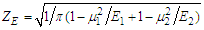 , where
  is the elastic coefficient of the gear material to consider the effects of elastic modulus and Poisson's ratio on Hertz stress. Equation (6) is simplified as:
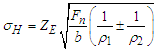 | (7) |
When two cylinders come into contact, the half width a of the contact surface is: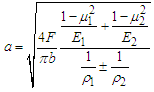 | (8) |
From equations (7) and (8), it can be seen that the contact surface between the bearing and the shaft, as well as the stress on the tooth surface, changes with the curvature radius. Therefore, when the gear system operates under load, the deformation of the tooth surface is time-varying and shows periodic changes. When there is an offset load on the tooth surface, the half width of the contact surface will also change.The bearing stiffness used on small reducers is generally 10N/μm-100N/μm. Here, bearing stiffness is selected as rigid bearing, 60N/μm, 70N/μm, and 80N/μm for calculation, analysis, and comparison. From Figure 5, it can be seen that when the elastic deformation of the bearing is not considered and a load is added to the gear, the shaft undergoes bending deformation from the origin; When considering the elastic deformation of the bearing and setting the axis in the Y direction, the axis will experience translation in both the X and Z directions. As the stiffness of the bearing decreases, the translation amount slowly increases.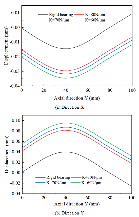 | Figure 5. Deformation of the active shaft |
3. Modeling and Modification Design of Gear System
3.1. Construction of Gear System Model
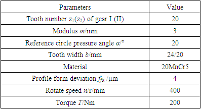
A pair of 5-level precision straight cylindrical gear pairs were selected, and the gear parameters are shown in Table 1. By using KISSsoft, a primary gear transmission system consisting of shafts and bearings was established, as shown in Figure 6, which makes the model closer to a real gear transmission system.Table 1. Basic parameters of gears
 |
| |
|
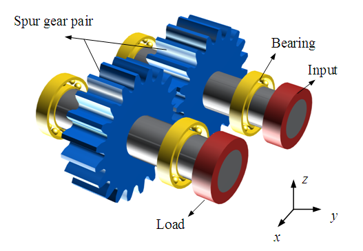 | Figure 6. First-stage gear drive system |
3.2. Design of Gear Modification Plan
KISSsoft software can automatically provide reference modification quantities based on various factors, including transmission error of gear rotation, normal force on tooth surface, and transmission acceleration, among which the tooth modification quantity is 30μm. Drum shape quantity is 10μm. In order to better improve the performance of gears, adopting a comprehensive modification method is an effective method. On this basis, multiple combinations of modification quantities and methods can be selected, and different combinations of modification schemes can be input into KISSsoft for calculation to obtain the modification results of different schemes, and the results can be analyzed to obtain the optimal scheme. The selection targets are the Peak-to-peak transmission error (PPTE), Torque amplitude of the driven gear (TA), and Average Hertz contact stress. The modification plans are numbered. Figure 7 shows the distribution of 125 modification plans.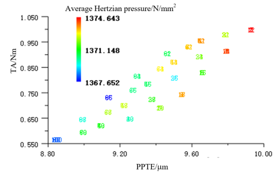 | Figure 7. Distribution of practice programs |
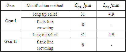
Based on the analysis results, the 62nd modification plan in the bottom left corner of Figure 7 was determined, as shown in Table 2, which involves performing tooth tip relief and flank line crowning on gear I and gear II. In the tooth tip relief, the modification amount  , and the modification length is
  ; In the flank line crowning, the modification amount
  .
.Table 2. Optimal modification scheme
 |
| |
|
4. Discussion
The modification results of this article are evaluated using transmission error, normal force, and transmission acceleration as indicators.The transmission error curve generated by the angle of one tooth rotation of the primary gear transmission system is shown in Figure 8. From the figure, it can be seen that the unmodified gear undergoes two sudden changes in transmission error for each tooth rotation distance during transmission, with a peak to peak transmission error of 16.1μm for the gear system. When the modified gear undergoes transmission, there is only one sudden change in transmission error, and the peak to peak transmission error of the gear system is 9.02μm, which reduced by 44%. Through comparison, it can be seen that gear modification plays an important role in reducing the peak to peak transmission error and vibration of gears.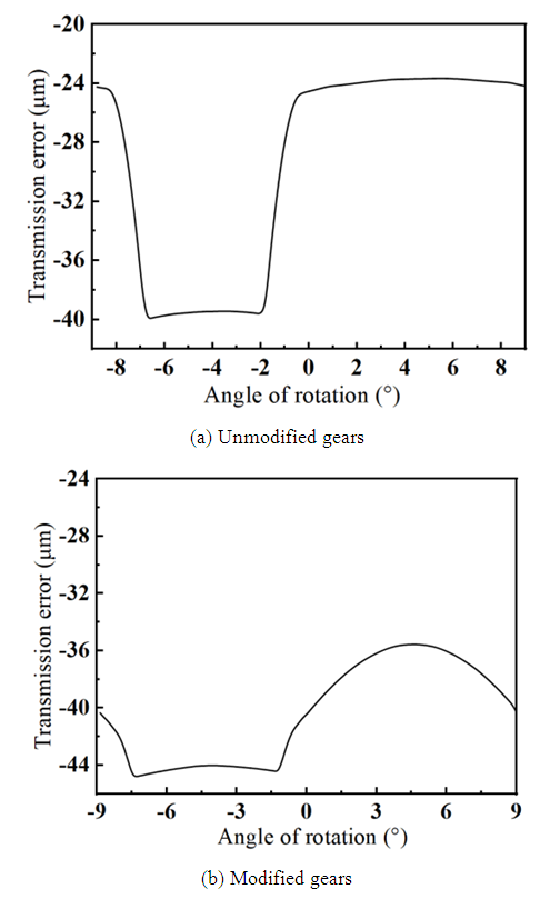 | Figure 8. Gear transmission error |
The distribution of normal force on the tooth surface reflects the bias load of the gear system. When designing a pair of gears, the tooth width of the small gear is usually 5mm-10mm wider than that of the large gear. Therefore, during heavy load meshing, the tooth surface of the small gear will undergo slight deformation after being squeezed, and the middle part along the tooth width direction will be inward concave, as shown in Figure 9.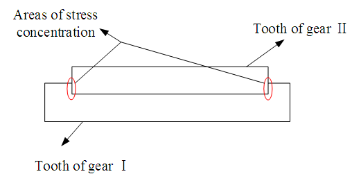 | Figure 9. Microscopic deformation of the tooth surface |
When the gear is not modified, the distribution of normal force is shown in Figure 10 (a). The color depth in the unrefined normal stress distribution diagram shows that the maximum value of normal stress on the tooth surface is distributed at both ends of the gear tooth surface. After the flank line crowning, this edge contact problem can be effectively solved. The normal force distribution on the tooth surface after the modification is shown in Figure 10 (b), the normal force distribution on the tooth surface is more uniform and the meshing area is located in the middle of the tooth surface. From the normal force curve before and after the modification in Figure 11, it can be seen that compared with the normal force curve on the tooth surface before the modification, the gear system after the modification has a smoother overall normal force on the tooth surface during the transmission process, with fewer abrupt changes, indicating a decrease in the meshing impact of the gear.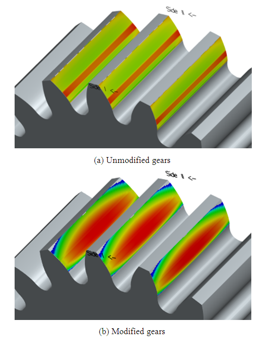 | Figure 10. Normal force distribution diagram of the gear tooth surface |
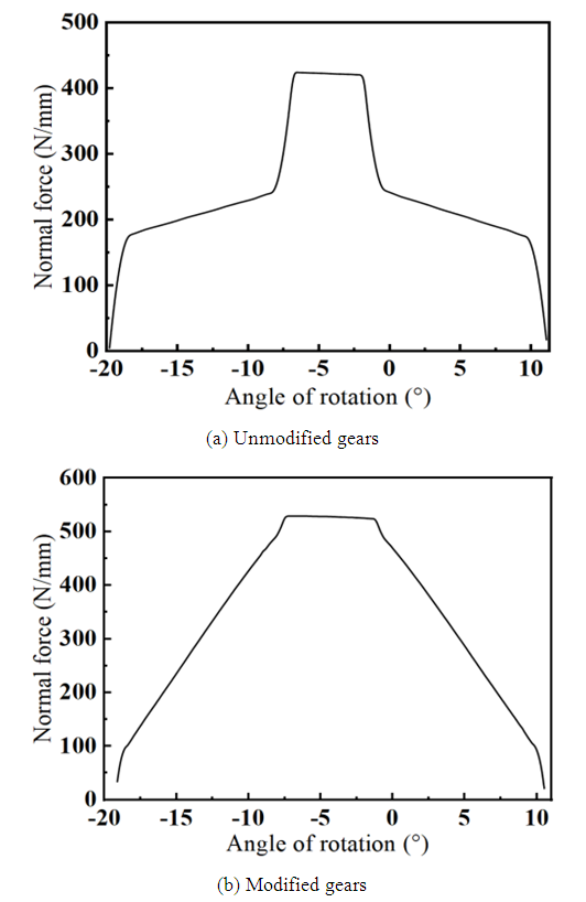 | Figure 11. Normal force curve of tooth flank |
The change in transmission acceleration can reflect the vibration and meshing impact of the gear system. The irregular change in transmission acceleration of the gear system has a significant impact on the stability, vibration, and noise of the gear transmission. The transmission acceleration of gears without modification and after modification is shown in Figure 12. From the figure, it can be seen that during the process of rotating one tooth, the transmission acceleration of gears without modification has two major sudden changes, with peaks of 75mm/s2 and 90mm/s2, respectively. However, when the modified gears rotate at the same angle, although there are also two major sudden changes in transmission acceleration, the peak values are both 38mm/s2. Therefore, the primary gear transmission system used in this section showed an average decrease of 52.5% in peak transmission acceleration after gear tooth modification, which plays an important role in improving the transmission stability of the gear system, reducing impact load, and increasing the service life of the gears.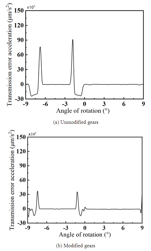 | Figure 12. Transmission acceleration |
5. Conclusions
(1) Under load, the shaft undergoes bending deformation. When considering the stiffness of the bearing, the shaft undergoes translation in both the x and z directions. As the stiffness of the bearing decreases, the amount of translation slowly increases. Therefore, both the shaft and bearings will generate displacement excitation, which will affect the transmission stability of the gear system.(2) The combination of gear tooth modification under various displacement excitations has a significant effect on improving the transmission error and acceleration of gears. When the modified gears are transmitted, the number of sudden changes in transmission error decreases, the peak to peak value of transmission error in the gear system decreases by 44%, and the average peak value of transmission acceleration decreases by 52.5%.(3) Compared with the normal force curve on the tooth surface before the modification, the gear system after the modification has a smoother overall normal force on the tooth surface during the transmission process, with fewer abrupt changes. The distribution of normal force on the tooth surface after the modification is more uniform, indicating that the meshing impact of the gear is reduced and the service life of the system is extended.
ACKNOWLEDGMENTS
This project is supported by Henan Provincial Science and Technology Project (NO. 222102210210).
References
| [1] | J Wei, G Q Wang, D T Qin. Nonlinear excitation and dynamic characteristics of helical gear system with considering modification [J]. Journal of vibration engineering, 2018, 31(04): 561-572. |
| [2] | O I Kosarev. On the Theoretical Foundation of Flanking and Profile Modification of Spur Gear Transmissions [J]. Journal of Machinery Manufacture and Reliability, 2015, 44(3): 221-226. |
| [3] | C J Bahk, R G Parker. Analytical investigation of tooth profile modification effects on planetary gear dynamics [J], Mechanism and Machine Theory, 2013, 70: 298-319. |
| [4] | A Z Hajjaj, K Corrigan, M Mohammadpour, et al. On the stability analysis of gear pairs with tooth profile modification [J]. Mechanism and Machine Theory, 2022, 174: 104888. |
| [5] | Z Tang, M Wang, Z Chen, et al. Design of Multi-Stage Gear Modification for New Energy Vehicle Based on Optimized BP Neural Network [J]. IEEE Access, 2020, 8: 199034-199050. |
| [6] | G Han, B Yuan, G Qiao. Tooth Surface Modification for Helical Gear Pairs considering Mesh Misalignment Tolerance [J]. Hindawi Limited, 2021. |
| [7] | X X Wang, S J Wang, W L Wang, et al. Research on Vibration and Noise Reduction of Planetary Reducer Based on Gear Micro-modification [J]. Machine Tool and Hydraulics, 2023, 51(01):7-11. |
| [8] | B Q Xia, Y H Zhang, Z B Zhang. Research on Spur Gear Profile Modification Based on Stiffness of the Elastohydrodynamic Lubrication Friction Pair [J]. Mechanical Transmission, 2023, 47(01): 17-26. |
| [9] | T L Si, K Li, J H Chen, et al. Research on Gear Helix Shaping Optimization [J]. Chinese Hydraulics and Pneumatic, 2022, 46(11): 116-123. |
| [10] | Q Zhang, Y Wang, W Lin, et al. Dynamic Performance of Gear Transmission System and Modification Optimization of Electric Vehicle Gearbox [J]. Journal of Coastal Research, 2020, 103(1): 366. |
| [11] | G P Yan, D H Yu, F Zhong. Dynamic Contact Stress Analysis of Spur Gear Modification Based on Modification Condition [J]. Mechanical design and manufacturing, 2020, 103(1): 366. |

 Abstract
 Reference
 Full-Text PDF
 Full-text HTML