-
Paper Information
- Paper Submission
-
Journal Information
- About This Journal
- Editorial Board
- Current Issue
- Archive
- Author Guidelines
- Contact Us
Journal of Mechanical Engineering and Automation
p-ISSN: 2163-2405 e-ISSN: 2163-2413
2023; 12(1): 1-5
doi:10.5923/j.jmea.20231201.01
Received: Feb. 9, 2023; Accepted: Feb. 24, 2023; Published: Mar. 2, 2023

Numerical and Experimental Studies of a Nonlinear Vibration System
 Abstract
 Reference
 Full-Text PDF
 Full-text HTML
Jasem Alrajhi1, Khalid Alkhulaifi1, Mohsen Alardhi1, Khaled Alhaifi1, Nawaf Alhaifi1, Ahmed Khalfan1, Jasem Alazemi1, Marya Alsaraf2, Ahmad Khalfan3
1College of Technological Studies, PAAET, Kuwait
2Kuwait Health Ministry, Kuwait
3Automotive and Marine Dept., College of Technological Studies, PAAET, Kuwait
Correspondence to: Jasem Alrajhi, College of Technological Studies, PAAET, Kuwait.
| Email: |  |
Copyright © 2023 The Author(s). Published by Scientific & Academic Publishing.
This work is licensed under the Creative Commons Attribution International License (CC BY).
http://creativecommons.org/licenses/by/4.0/

By examining friction pairs surface structural features and using theory of contact mechanics, contact mathematic prototype of microscopic units of thermal distortion friction pairs is made. Using mathematical statistics and normalization method, microscopic model can be removed to macroscopic mathematic model, and then the elastic contact features of friction pairs can be premeditated. A nonlinear dynamic model with five degrees-of-freedom for a four-wheel-drive vehicle driveline coupled by a cardan joint, counting dynamic connection angle, nonconstant velocity, and supplementary instant caused by the cardan joint, is recognized by using the Lagrange method to analyse the driveline coupling vibration in both torsional and lateral directions. High-order Runge–Kutta algorithm is practical to solve the differential equations and to calculate momentary replies of the driveline rotors under acceleration state. The colour maps and second-order vibration of the driveline are attained by frequency spectrum analysis and order tracking analysis, respectively. The second-order vibration and noise of the driveline and vehicle interior caused by the cardan joint is authenticated by vehicle tentative results and condensed efficiently by reducing intersection angle of the cardan joint under the functioning condition. Results shows that application of an elastic coupling as an alternative of the cardan joint knowingly diminishes the second-order vibration but instantaneously creates low-level third-order vibration.
Keywords: Nonlinear vibration Numerical Experiment
Cite this paper: Jasem Alrajhi, Khalid Alkhulaifi, Mohsen Alardhi, Khaled Alhaifi, Nawaf Alhaifi, Ahmed Khalfan, Jasem Alazemi, Marya Alsaraf, Ahmad Khalfan, Numerical and Experimental Studies of a Nonlinear Vibration System, Journal of Mechanical Engineering and Automation, Vol. 12 No. 1, 2023, pp. 1-5. doi: 10.5923/j.jmea.20231201.01.
Article Outline
1. Introduction
- In the case of high line speed, the friction pairs of shift clutch of vehicle transmission system will produce thermal distortion in the process of obligatory separation, which will cause vibration and extremely affect the performance of friction element and others related components. The thermal deformation of the friction pairs and its vibration are essential to the design of the clutch of vehicle power-shift steering transmission device. Consequently, it is of significant theoretical and engineering implication to study deeply on the vibration appearances of the friction pairs at high line speed, and to put onward an actual vibration control method to recover the service life of the friction pairs. By appertain the theory and technology of surface structure features and contact mechanics of friction pairs, from the belvedere of micro mechanics, a microscopic normal element contact model of thermal distortion is recognized. Then making full use of mathematical statistics and standardization methods, the revolution connection between micro and macro is established. Hence, a macro contact mathematical model between two pairs of frictional pairs is obtained. At the same time, with presenting Kelvin-Voigt model and growing the viscoelastic contact differential operator into mathematical model, the viscoelastic contact property including stress and strain is constructed, and a viscoelastic contact mathematical model of the friction pairs can be obtained. At last, the mathematical model of nonlinear vibration is obtained by mechanical analysis, and its vibration characteristics are simulated [1]. The nonlinear vibration characteristics are tested under different rotational speed and lubricating oil, the accuracy of the simulation model is verified.The passive vibration control of key and subharmonic concurrent resonance for the Duffing-type nonlinear system under the base innervation and external innervation by using magnetorheological (MR) fluid damper is studied, where the fractional-order derivative Bingham model of MR fluid damper is measured [2,3]. The estimated logical solution of the system is attained by using the incremental averaging method. Based on gaining the principal resonance of the system under base innervation by the averaging method, the subharmonic resonance solution of the system is obtained by taking the subharmonic resonance of the system under base innervation and external innervation as an increase so as to obtain the estimated analytical solution of the concurrent resonance of primary and subharmonic resonance [4,5,6]. And the amplitude–frequency equation and phase–frequency equation of the steady-state solutions for the primary and subharmonic resonance of the system are derived respectively. According to the approximate analytical solutions, the steadiness conditions of the steady-state solution of the primary resonance and subharmonic instantaneous resonance are obtained by Lyapunov method.
2. Literature Survey
- Al-Mosawe et al. [1], studied the large amplitude nonlinear vibration behaviours of an initially stressed cross-ply composite laminated plate and indicated that the nonlinear dynamic responses are sensitive to the vibration amplitude, aspect ratio, thickness ratio, modulus ratio, stack sequence, layer number, and state of initial stresses. Borowski et al. [2], analysed the nonlinear free vibrations of composite laminated thin plates. Caruntu et al. [3], investigated the nonlinear dynamic behaviours and the chaotic motions of a parametrically excited simply supported rectangular symmetric cross-ply laminated composite thin plate. Krack et al. [4], studied the nonlinear dynamics of a parametrically excited simply supported laminated composite plate and found that there exist the multiple steady bifurcation solutions and jumping under the certain conditions. Lu et al. [5], investigated the bifurcations and chaotic dynamics of a composite laminated piezoelectric rectangular plate with one-to-two internal resonance. Vakakis et al. [6], developed an analytical approximation to solve large amplitude nonlinear free vibrations of a simply supported laminated cross-ply composite thin plate. Kluger et al. [7], studied the nonlinear dynamics and chaotic motions of an angle-ply composite laminated thin plate using third-order shear deformation plate theory. Krack et al. [8], analysed the influence of the quadratic and cubic terms on the nonlinear dynamic characteristics of an angle-ply composite laminated rectangular plate under combined parametric and external excitations. Lu et al. [9], analysed the nonlinear dynamics of a simply supported FGM plate subjected to the transverse and in-plane excitations in a thermal environment. Nayfeh et al. [10], studied the chaotic vibrations of an orthotropic FGM rectangular plate by considering the heat conduction and temperature-dependent material properties. Vakakis et al. [11], investigated the nonlinear oscillations of a cantilever FGM plate based on the third-order deformation plate theory and the asymptotic perturbation method. The various reserchers analysed the nonlinear dynamic responses of a clamped-clamped FGM circular cylindrical shell subjected to an external excitation and uniform temperature change [12,13,14,15].Using asymptotic perturbation method based on the Fourier expansion and the temporal rescaling, Zewen et al., Yingbing et al. [16,17], investigated the nonlinear oscillations and chaotic dynamics of a simply supported FGM plate.
3. Mathematical Model of Nonlinear Vibration in Sliding Process
- 1. Dynamic modelA wet clutch friction pair of vehicle transmission system is composed of alternating contact the friction disk and the toroidal dual steel plate. The vibration model of friction pairs of clutches may be divided into several sub vibration models, which means the model is made up of several sub vibration models in series as shown in Figure 1. Each sub vibration model is related to each other by the moment “M” and the axial force “Fn” and each sub model contains only one pair of friction pairs. Based on dynamics and contact mechanics, sub dynamic model can be shown. There, function “Fnc” between two contact faces is normal contact force which is made up of scalar sum of elastic contact force and viscoelastic contact force, and function “Fkn” is structural stiffness elastic force, and “Fc” is damping force.
 | Figure 1. System schematic diagram |
 | (1) |
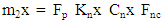 | (2) |
 | (3) |
 | (4) |
4. Methods
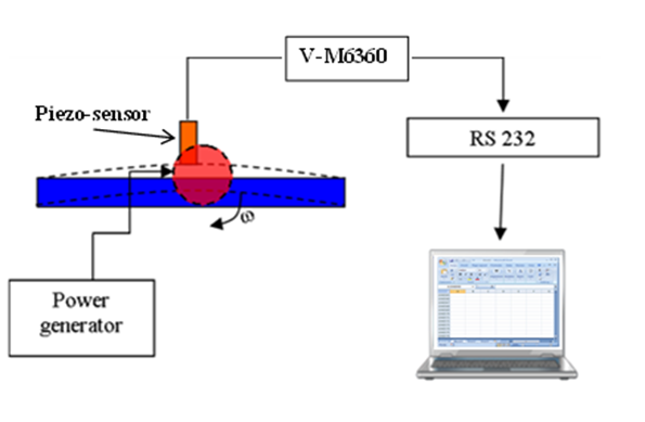
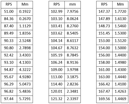
- As the sensor was attached directly at a point on the steel bar to be assumed as the maximum displacement point, the acceleration measurements have been sensed in voltage output. The voltage signal acquired by the sensor was primarily converted by RS 232 from analogue to digital before stored in local PC hard drive and displayed on the PC monitor in real time through the vibrometer software. As the entire test rig components were constructively built, the angular speed of the unbalanced mass should be calibrated. Non-contact tachometer modelled DT-2236 was used to measure the angular speeds of the unbalanced mass when the voltages were varied. To gain the response of the system in frequency domain, the following steps have been done:1) The voltage of the DC supplier was calibrated with the tachometer to find the relation between the voltage and excitation frequency. In other word, when, the voltage of the DC motor was changed by the DC supplier each time, the frequency of the rotating disc was measured by tachometer. 2) The frequency of excitation has been changed gradually to find the natural frequency of the system. In the natural frequency of the beam, it has been expected to receive maximum amplitude.3) Around the natural frequency of the system, several runs have been done to find the time response of the system at each frequency of excitation. 4) Maximum amplitude of the vibration has been selected from the time domain at specific excitation frequency.5) The maximum amplitude at time domain has been drowned verses the related excitation frequency to have the response of the system in frequency domain.The results of experimental and numerical analysis have been compared for a linear system and a system with nonlinear spring. In the following, the experimental results have been depicted.
5. Result
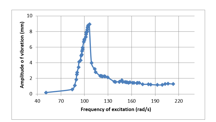
|
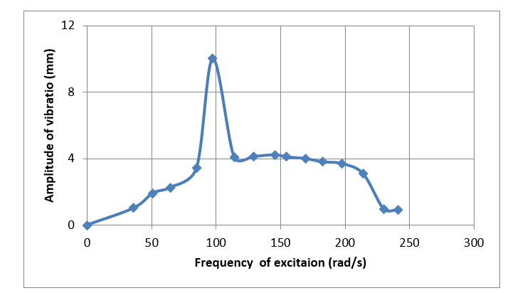 | Figure 2. Amplitude of a system without Mag-spring (as the source of nonlinearity) against the excitation frequency of the system |
 | Figure 3. Amplitude of a system with Mag-spring (as the source of nonlinearity) against the excitation frequency of the system |
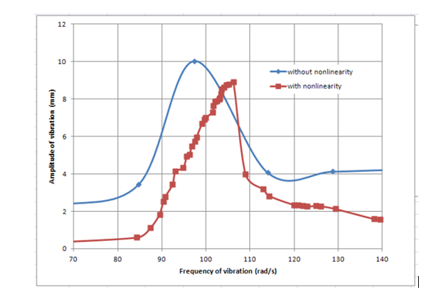 | Figure 4. A comparison between two systems with and without nonlinearity (Mag-spring) |
6. Discussion
- The first part of the study showed how adding Mag-spring as nonlinear stiffness with a hardening behaviour to a single degree of freedom system could protect the system from unwanted vibration at its natural frequency. When the magnitude of the vibration in the system increases because of resonance, automatically the system updates itself and the stiffness of the system will increase as well. The Increase in stiffness will change the natural frequency of the system and as a result it shifts the resonance to a higher frequency. This method leaves the primary system at its designed stiffness, while the system working normally out of resonance range and the stiffness only increases where it is necessary to avoid resonance. Also, the results were compared with the system without any absorber and with a linear absorber. Moreover, the effect of amplitude of the excitation force, F_0, has been studied on the system. In addition, it has been shown how the mass ratio (mass of the absorber over mass of the main system) could modify the natural frequency of the system with two degrees of freedom.
7. Conclusions
- A nonlinear dynamic model with five degrees-of-freedom for a four-wheel-drive vehicle driveline has been studied. A nonlinear hardening spring was added numerically and experimentally in parallel to a single degree of freedom (SDOF) system. Results showed that nonlinearity could enhance the behaviour of a system at its primary natural frequency while it is not disturbing the system’s stiffness in normal working range (SDOF self-regulating system). Results also showed that nonlinearity could shift the resonance frequency of the SDOF system by 10% (hardening of the system), without affecting the stiffness of the system at normal working condition. The nonlinear absorber could reduce the amplitude of vibration of the main system better than the linear absorber. Moreover, the cancellation range (ω_n1-ω_n2) was wider about 5% to 10% depending on the system parameters. Damping ratio is important in this kind of design as could seriously affect the cancellation amplitude which is directly used at design of nonlinear absorber. Also, there is an important issue while designing a nonlinear absorber that the amplitude of the absorber should remain limited to the defined area of the nonlinearity.