Xiaozhuan Chen1, Pan Wang1, Xuefeng Meng1, Beile Zhang2, Xiufang Liu2
1School of Mechanical and Power Engineering, Henan Polytechnic University, Jiaozuo, China
2School of Energy and Power Engineering, Xi’an Jiaotong University, Xi’an, China
Correspondence to: Xiaozhuan Chen, School of Mechanical and Power Engineering, Henan Polytechnic University, Jiaozuo, China.
| Email: |  |
Copyright © 2022 The Author(s). Published by Scientific & Academic Publishing.
This work is licensed under the Creative Commons Attribution International License (CC BY).
http://creativecommons.org/licenses/by/4.0/

Abstract
To meet the environmental requirements, the air-conditioning system of an electric vehicle is chosen as the research object. In this study, under the same operating conditions, the differences in cycle characteristics of R134a, R513A, and R152a refrigerants have been investigated theoretically and experimentally. The REFPROP 9.1 software is used to extract the thermodynamic properties of the refrigerants, and the thermodynamic performance is simulated in a basic vapor compression system cycle. To study the effects of ambient temperature as well as compressor speed on performance characteristics, an electric vehicle air conditioning system with a secondary loop was designed and built. The results that the cooling capacity and outlet air temperature of R513A and R152a systems are similar to that of R134a, but the coefficient of performance (COP) of the R152a system is 13% and 15% higher than that of R134a and R513A, respectively. The ambient temperature and compressor speed have a clear impact on cooling performance. The COP declines dramatically at high ambient temperature and compressor speed. R152a can be considered a promising alternative to R134a system for its low cost, and high efficiency, which enhances the driving range.
Keywords:
Low global warming potential (GWP), Electric vehicles, Ambient temperature, Compressor speed
Cite this paper: Xiaozhuan Chen, Pan Wang, Xuefeng Meng, Beile Zhang, Xiufang Liu, Investigation of Using R134a, R513A, and R152a as the Refrigerant in the Air-Conditioning System of Electric Vehicles, Journal of Mechanical Engineering and Automation, Vol. 11 No. 1, 2022, pp. 19-26. doi: 10.5923/j.jmea.20221101.03.
1. Introduction
As global warming, climate deterioration, and the scarcity of fossil fuels become more serious, energy conservation and environmental protection have increasingly important [1]. Traditional fuel cars deplete oil resources, harm the environment, and their energy utilisation rate is very low, but electric vehicles have the advantages of environmental protection, high energy efficiency, and energy diversification, making their development critical. [2-4]. At present, driving range and environmental adaptability is the key factor restricting the rapid development of electric vehicles. As the auxiliary subsystem with the largest energy consumption of electric vehicles, the reduction of energy consumption of the air-conditioning system is crucial to improve the electric vehicles' endurance. [5]. Because electric vehicles have no engine and insufficient waste heat utilization, electric vehicles typically employ the low-efficiency PTC (Positive Temperature Coefficient) electric heater for heating, which seriously affects the driving range of electric vehicles [6]. While the heat pump system may expand the energy efficiency of the heat pump air-conditioning system of electric vehicles, increase the driving range of electric vehicles, to increase electric vehicles' environmental adaptability [7,8]. As a result, the heat pump system begins to be applied in electric vehicles instead of the PTC heater.Since high GWP (Global Warming Potential) refrigerants might exacerbate the greenhouse impact, countries around the world began to introduce relevant policies to limit high GWP refrigerants. To reduce HFCs (hydrofluorocarbons) emissions, the F-GAS regulation of the European Union bans the usage of refrigerants with GWP values higher than 150 in vehicle air conditioners from 2017. Other countries have taken similar steps to limit the usage of R134 in newly produced cars. Hence, phasing out R134a for automobile air conditioning has become a popular trend [9,10]. Although R134a has zero ODP (Ozone Depletion Potential) and good thermodynamic performance, which is a refrigerant typically used for automobile air conditioning, its GWP is 1430. Has a result, R134a is gradually being replaced by low GWP refrigerants [11]. R513A is a binary azeotrope refrigerant made up of R134a and R1234yf with a mass fraction ratio of 44/56, and its GWP is 631. Despite the fact thatR513A does not comply with the European Union regulations, its GWP value is much lower than R134a, and it has thermal physical properties similar to R134a, which can be utilized as a temporary refrigerant in the environment. Currently, R513A has been studied by a number of academics. Yang et al. [12] carried out household refrigerator experimental research and found that R513A can be directly charged to replace R134a, and the performance of R513A is comparatively better. Sun et al. [13] used an economized-cycle vapor compression refrigeration system as an example to investigate the energy and exergy performance of R513a used as a drop-in replacement of R134a. According to the analysis, a system with drop-in R513A shows reduced capacity by up to 12% and efficiency (up to 9% with COP and 14% with energy efficiency ratio) under most operating conditions, while exhibiting less irreversibility (5% to 13%) under high-ambient, high-space temperature conditions and a better energy efficiency ratio of 3% in low-ambient conditions. Meng et al. [14] carried out experimental comparative tests on the mixed refrigerant R1234yf and R134a (mass ratio 89/11) under diverse refrigeration and heating circumstances.. It was observed that the exhaust temperature of the mixed refrigerant was about 10°C lower than R134a, and it’s COP (coefficient of performance) of cooling and heating was 4%-9% and 4%-16% lower than R134a, respectively. Mota-Babiloni et al. [15] utilized the steam compression system test bench to conduct comparative experimental tests on R513A and R134a at various condensation temperatures and evaporation temperatures. The results showed that R513A had a lower discharge temperature. Although the latent heat of R513A is lower than R134a, the suction density of R513A was higher and the mass flow rate was larger, resulting in a higher cooling capacity of R513A systems than that of R134a.The GWP of R152a is just 137, and thermodynamic properties are close to R134a, therefore, R152a is a refrigerant that can be used as a substitute for R134a. [16]. Chen et al. [17] tested the performance of R152a and R134a in oil-free domestic refrigerators under different operating conditions. The results showed that the EER (average energy efficiency ratio) of R152a was about 26% higher than R134a, and R152a has 7% higher energy efficiency than R134a. Bolaji [18] experimentally studied and compared the performance of R134a and R152a in the VCR (vapor compression refrigeration) system. According to the findings, the average COP of R152a was 4.7% higher than that of R134a, and R152a consumed less energy. Sanchez et al. [19] tested and compared five refrigerants (R1234yf, R1234ze(E), R600a, R290, and R152a) with the potential to replace R134a. The results showed R152a reduced the cooling capacity and compressor power consumption by 5.7% and 8.8%, respectively, when compared to R134a, while increasing COP by 1% -4.8%. Chen et al. [20] investigated the performance of R152a, R1234yf, and R134a in an oil-free VCR system. R1234yf was found to be similar to R134a in the study, in terms of working pressure and temperature, but the cooling capacity and COP of R1234yf are 11% and 16% lower than R134a, respectively, despite the fact R152a has higher volume efficiency, adiabatic efficiency, and cooling capacity, and its cooling capacity and COP are 13% and 6% higher than R134a, respectively. Although flammability limits the usage of R152a in traditional automotive air conditioning, R152a is more promising than R1234yf to replace R134a in oil-free automotive air-conditioning systems.In spite of a number of studies mentioned above, there are very few studies on R513A and R152a in an electric vehicle heat pump air conditioning system. The performance of R134a, R152a and R513A refrigerants was compared both conceptually and experimentally in this study. This study differs from previous studies in the following ways: (1) Thermodynamic performance of R513A and R152a are compared to R134a in basic vapor compression system cycle, (2) An electric vehicle air conditioning system with a secondary loop was designed and R134a, R152a and R513A refrigerants were tested in the enthalpy difference laboratory, (3) The impacts of refrigerant charge amount, ambient temperature and compressor speed were investigated experimentally, and the cooling performances of systems using various refrigerants ware compared. The purpose of this study is to determine the feasibility of R513A and R152a to replace R134a in an automotive air conditioning system and expect to provide some references for R134a refrigerant replacement research.
2. Theoretical Analysis
2.1. Comparison of Refrigerants Thermal Properties
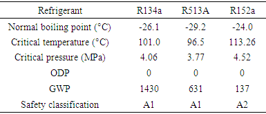
The refrigerants utilised in the experiment were R134a, R513A, and R152a. The thermodynamic characteristics of the three refrigerants are close to each other, as shown in Table 1.Table 1. Properties of refrigerants
 |
| |
|
The saturated steam pressures of the three refrigerants under different temperatures at various temperatures are shown in Figure 1 (a), the saturated steam pressures of R513A are slightly lower than R134a, while the saturated steam pressure of R152a is slightly lower than that of R513A. Therefore, the saturated steam of R513A is closer to R134a than R152a. The density curves of saturated gas and saturated liquid at different temperatures can be seen in figure 1 (b). It can be seen from Figure 1 (b) that the density curves of saturated liquid and saturated gas show opposite trends with the temperature changes. The saturated liquid density of refrigerants is closely related to the amount of refrigerant charge. The lower the liquid density, the less optimal refrigerant charge is required. The saturated liquid density of R152a is the least at the same temperature, and the amount of refrigerant charged is also the smallest. As the compressor inlet is gaseous, the gas density affects the mass flow rate of the system. The higher the vapor density, the larger the mass flow rate. Thus, the mass flow rate of the R513A system is the largest, as well as the mass flow rate of the R152a system is the smallest.Figure 1 (c) shows the pressure-enthalpy diagram of the three refrigerants. It can be illustrated from Figure 1 (c) that R513A is closer to R134a, while R152a is quite different from R134a. At similar operating pressures, R152a has a higher latent heat of phase change, about twice R513A, which indicates that R152a requires a smaller mass flow rate of refrigerant to acquire the same cooling/heating capacity.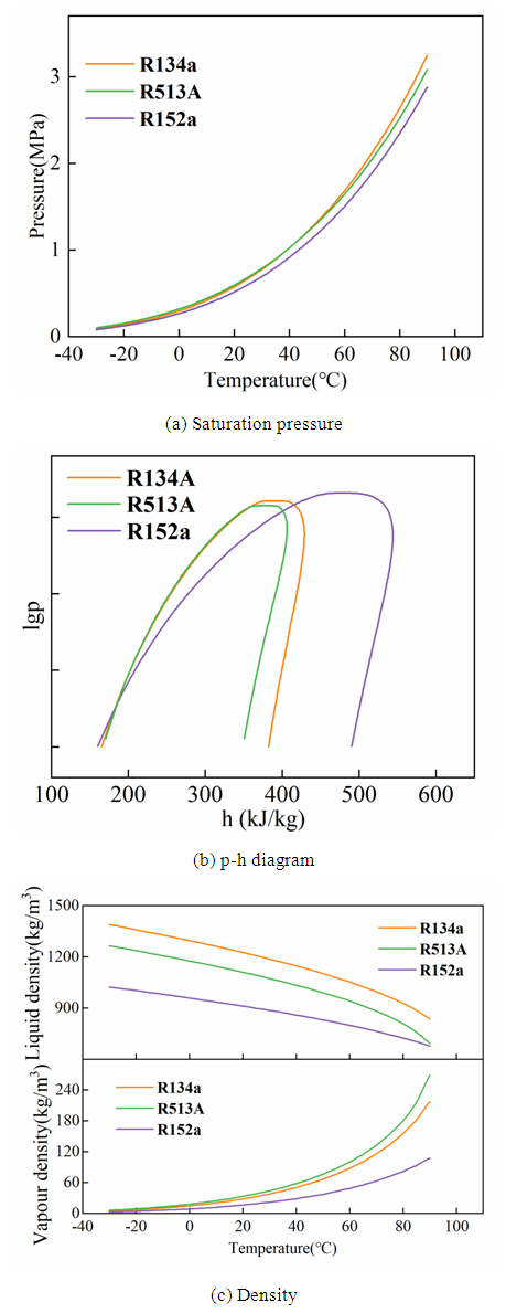 | Figure 1. Comparison of thermal properties of refrigerants |
2.2. Thermodynamic Model of the Air-conditioning System
To compare R513A, R152a and R134a theoretically, this paper simulates the theoretical cycle of single-stage steam compression refrigeration. The pressure-enthalpy diagram of the system is shown in Figure 2. The following assumptions are made, (a) pressure drops as well as heat losses are ignored in the system operation; (b) the throttling process in the expansion valve is a constant enthalpy; (c) the compressor has ideal volumetric efficiency and isentropic efficiency of 85% and 80% respectively.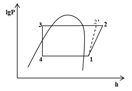 | Figure 2. p-h diagram of the theoretical cycle |
The thermodynamic theoretical calculation is carried out by calling the enthalpy value of each state point, and the theoretical unit mass cooling capacity can be calculated by Eq. (1): | (1) |
Where q0 is the unit mass cooling capacity, h1 and h4 are the specific enthalpy of the refrigerant at evaporator inlet and outlet, respectively.The volumetric cooling capacity can be calculated though Eq. (2): | (2) |
Where  is the unit volume cooling capacity,
  is the specific volume of the saturated refrigerant at the compressor inlet.The unit mass power consumption can be calculated with Eq. (3):
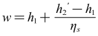 | (3) |
Where w is the unit mass power consumption,  is the superheated vapor enthalpy at the compressor exit for an isentropic compression process.Assume that the compressor speed of 3000r/min and a displacement of 34cm3/r. The theoretical mass flow rate can be calculated as Eq. (4):
 | (4) |
Where n is the compressor speed, V is the compressor displacement,  is the volumetric efficiency.The theoretical coefficient of performance can be calculated by Eq. (5):
 | (5) |
2.3. Theoretical Results
2.3.1. Performance under the Typical Operating Condition
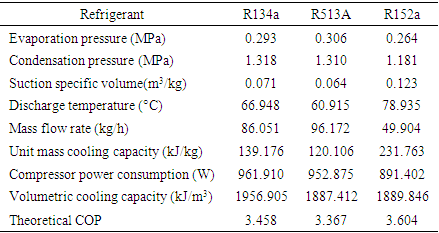
Assume that the subcooling and superheat are 5°C, the condensation temperature is 50°C, and the evaporation temperature is 0°C. The calculation results are shown in Table 2. It can be seen from the table that the condensation pressure and evaporation pressure of R513A and R134a are similar, while R152a has lower condensation pressure and evaporation pressure than R513A and R134a. In contrast to the R134a system, the discharge temperature of R513A system decreases by 9%, while the discharge temperature of R152a system increases by 18%. Despite the fact that R152a has the highest unit mass cooling capacity, the volume cooling capacity of the three refrigerants is similar to each other due to the influence of the suction specific capacity on the mass flow rate. Moreover, the COP of R152a is the largest, the COP of R513A is the smallest.Table 2. Theoretical cyclic calculation results
 |
| |
|
2.3.2. Performance at Different Evaporation Temperatures
The cooling capacity of different refrigerants can be represented by volumetric cooling capacity. Refrigerants with similar volumetric cooling capacity are conducive to direct charging in the system. To compare the volume cooling capacity and COP of R513A, R152a, and R134a at different evaporation temperatures theoretically, the volume cooling capacity and COP of R513A, R152a, as well as R134a at different evaporation temperatures (-10°C, -5°C and 0°C) had been simulated. It could be illustrated from Figure 3 that with the augment of evaporation temperature, the volume cooling capacity and COP increase. When the evaporation temperature is -10°C, the unit volume cooling capacity of R513A and R152a is 3.4% and 1.6% lower than R134a, respectively. R513A and R152a have a little difference when the evaporation temperature is 0°C, which is 3.5% and 3.4% lower than R134a, respectively. The theoretical COP of R152a is the largest, and R513A is the smallest of the three refrigerants under the three work conditions. R134a, R513A, and R152a have COPs of 2.64, 2.55, and 2.78, respectively, when the evaporation temperature is -10°C. The COP of R134a and R513A is 5.0% and 8.3% lower than R152a, respectively.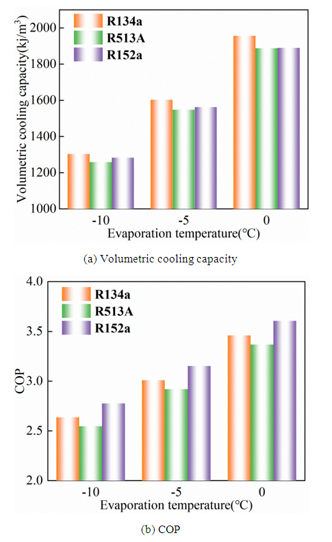 | Figure 3. The theoretical results |
3. Experiment
3.1. Experimental Bench and Procedure
In this paper, an electric vehicle heat pump air conditioning system with a secondary loop is established. Electromagnetic globe valves govern the heat pump system's switching between cooling and heating modes. When the heat pump air conditioning system is switched to cooling mode, the solenoid valve and EXV2 (electronic expansion valve) on the heating loop is fully closed. The compressed refrigerant gas is exothermic in the outdoor heat exchanger, which is used as a condenser. The EXV1 then throttles the refrigerant, which then flows into the HVAC (Heating Ventilation and Air Conditioning) system to absorb heat. When the system is switched to heating mode, the refrigerant first exchanges heat with the ethylene glycol solution in the secondary loop in the plate heat exchanger. The EXV2 then throttles the refrigerant as it flows into the outside heat exchanger, which serves as an evaporator. The ethylene glycol solution is used to provide heat to the cabin in the secondary loop, which can be assisted by the PTC heater. The system’s principle and pressure and temperature measuring sites are shown in Figure 4.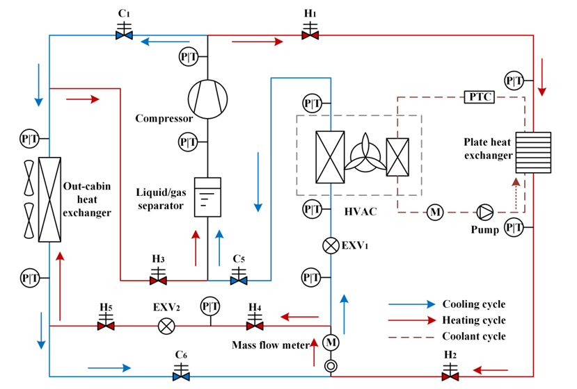 | Figure 4. Schematic diagram of experimental setup |
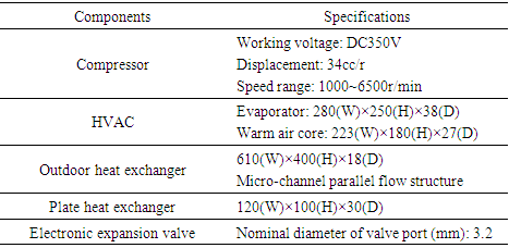
The experiment was carried out in the enthalpy difference chamber, with the temperature and humidity of the indoor and outdoor sides of the enthalpy difference chamber being controlled to imitate internal and environmental conditions. HVAC assembly is arranged on the indoor side, and other components are arranged on the outdoor side. The electric vehicle air-conditioning system designed in this paper is composed of a compressor, outdoor heat exchanger assembly, plate heat exchanger, electronic expansion valve, HVAC assembly, electromagnetic cut-off valve, and other components. Each component is connected by an automobile air conditioning hose with a corresponding size crimped aluminum joint at both ends. The primary components of the electric vehicle air-conditioning system are shown in Table 3.Table 3. Specifications of the experimental setup
 |
| |
|
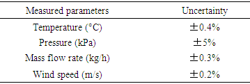
The temperature and pressure of the refrigerant were measured by thermocouples and pressure sensors respectively, refrigerant mass flow rate measurement by the mass flow meter. Table 4 shows the measurement accuracy of the main parameters.Table 4. Measured parameters and equipment uncertainty
 |
| |
|
3.2. Equation
The cooling capacity is assessed using the enthalpy potential method in this experiment. The compressor power consumption is measured by Qingdao Qingzhi power measuring instrument. The following formula can be used to calculate the cooling capacity and COP: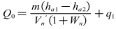 | (6) |
 | (7) |
3.3. Test Conditions
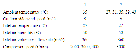
The test conditions are shown in Table 5. To compare the system performance of the three refrigerants following the same conditions, determining the optimal refrigerant charge is the precondition. The influence of ambient temperature and compressor speed on system performance is investigated experimentally under the optimal refrigerant charge.Table 5. Test conditions
 |
| |
|
4. Experimental Results
4.1. Optimal Refrigerant Charges Determination
The refrigerant charge has a significant influence on the air-conditioning system of electric vehicles. To obtain the optimal performance, critical charges of R134a, R513A, and R152a were determined firstly by experiments. The critical charge is usually determined by comparing cooling capacity and COP. The exit temperature of the HVAC module tends to become stable, and capacity or COP reaches the peak value gradually with increasing refrigerant charge, maintaining slight variation after that. Under the compressor speed of 3000 r/min, the critical refrigerant charges of R134a, R513A, and R152a are determined to be 650g, 625g, and 450g, respectively, based on charges in cooling capacity and COP. The critical charge of R513A and R152a is 5% and 32% lower than R134a, respectively. It's due to R513A and R152a having lower liquid densities. All of the experimental results are based on the critical charge amounts.
4.2. Influence of Ambient Temperature
Figure 5 shows the mass flow rate and outlet air temperature of R134a, R513A, and R152a as a function of ambient temperature. The refrigerant Mass flow rates of and outlet air temperature are significant parameters of the air-conditioning system. With the augment of the ambient temperature at 3000r/min, the mass flow rate has a slight growth. The mass flow rate of R513A is 17.4% and 82.8% more than that of R134a and R152a, respectively. It’s determined by the vapor density of refrigerants. The outlet air temperature decreases in a quite similar decreasing trend with increasing ambient temperature, although there is minimal difference in air temperature between the three refrigerants. The output temperature rises from 11.9°C to 13.2°C when the ambient temperature rises from 27°C to 43°C.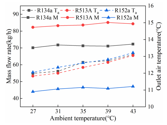 | Figure 5. Mass flow rate and outlet air temperature with ambient temperature |
Figure 6 shows the cooling performance at various ambient temperatures. It can be noted that the cooling capacity and COP decrease with the ambient temperature. When the ambient temperature increases from 27°C to 43°C, the cooling capacity of R134a, R513A, and R152a systems decreases from 2932W to 2609W, 3005W to 2639W, and 2928W to 2643W, respectively, while the COP decreased by 34.9%, 35.6% and 39.3%. This indicates that higher ambient temperature in summer results in severe degradation of the cooling performance. Moreover, the cooling capacity of R152 and R513A systems is similar to R134a, the cooling capacity of the R513A system is 2.2% and R152a is 0.3% more than that of R134a. Nevertheless, influenced by the input power, the COP of the R513A system is 2.4% lower and R152a is 14.3% higher than R134a, respectively.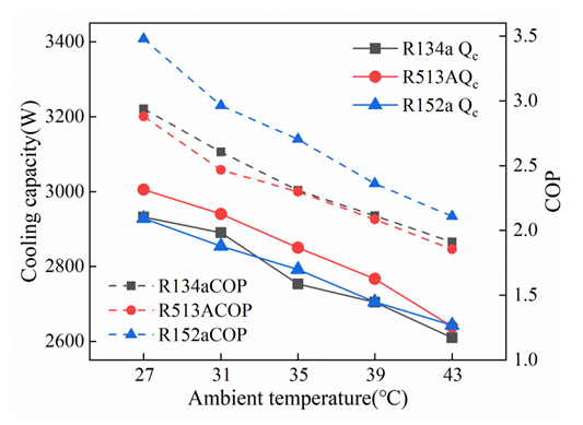 | Figure 6. Cooling capacity and COP with ambient temperature |
4.3. Influence of Compressor Speed
Figure 7 shows the response of the mass flow rate and outlet air temperature under different compressor speeds. As the compressor speed gets higher, the mass flow rate increases, while the outlet air temperature gradually decreases. The mass flow rate of R134a, R513A, and R152a system increases from 57.1kg/h to 80.5kg/h, 66.9kg/h to 94.1kg/h, and 35.2kg/h to 53.6kg/h, respectively, when the compressor speed is increased from 2000 r/min to 4000 r/min. The outlet air temperature reflects the cooling performance of the system. At 3000 r/min, the outlet air temperature of R134a, R513A, and R152a systems is 12.6°C, 12.3°C, and 12.6°C, respectively.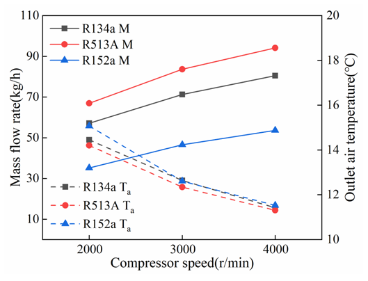 | Figure 7. Mass flow rate and outlet air temperature with compressor speed |
Figure 8 shows the influence of compressor speed on cooling performance. The mass flow rate increases with the increase of speed at the same ambient temperature, increasing the capacity of the heat exchanger. Meanwhile, the compressor power consumption increases, and the increase rate is higher than capacity. COP decreases with compressor speed. Figure 8 illustrates that the cooling capacity between these three refrigerants is very close to each other, and the maximum difference is within 10%. Overall, the average COP of R513A is 1.7% higher than that of R134a, while R152a presents an average 13% lower COP than R134a. At the ambient temperature of 35°C and the compressor speed of 3000r/min, the cooling capacity of R134a, R513A, as well as R152a are 2753W, 2850W, and 2792W, respectively, while the COP is 2.35, 2.30, and 2.70, respectively.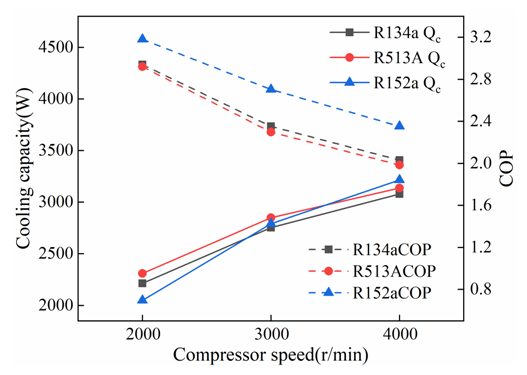 | Figure 8. Cooling capacity and COP with compressor speed |
5. Conclusions
In this study, the cooling performance of R134a, R513A, and R152a was investigated theoretically and experimentally under various ambient temperatures and compressor speeds, as well as the possibility of replacing R134a with R513A and R152a was analyzed. The main conclusions are as follows:(1) In theoretical analysis, R152a has a higher COP than R134a and R513A. The volumetric cooling capacity and COP increases gradually as the evaporation temperature increases. (2) The cooling performance is influenced by ambient temperature and compressor speed. Decreasing the ambient temperature or increasing the compressor benefit to improve the cooling performance, but the COP drops greatly at the high ambient temperature and high compressor speed.(3) Due to the different thermophysical properties of the refrigerants, the mass flow rate of R513A is 17.4% and 82.8% more than that of R134a and R152a, respectively.(4) The drop-in cooling capacity of the system with R513A and R152a is very close to that with R134a, but COP varies from each other. R152a presents the highest COP, the average COP of R152a is 13% and 15% higher than that of R134a and R513A.As a result, R513A can be used as a transitional alternative before the ban of R134a for the GWP value is 631. R152a can be considered a promising alternative for the low GWP, low cost, and high COP. But a series of safety modifications are needed for the flammability of R152a.
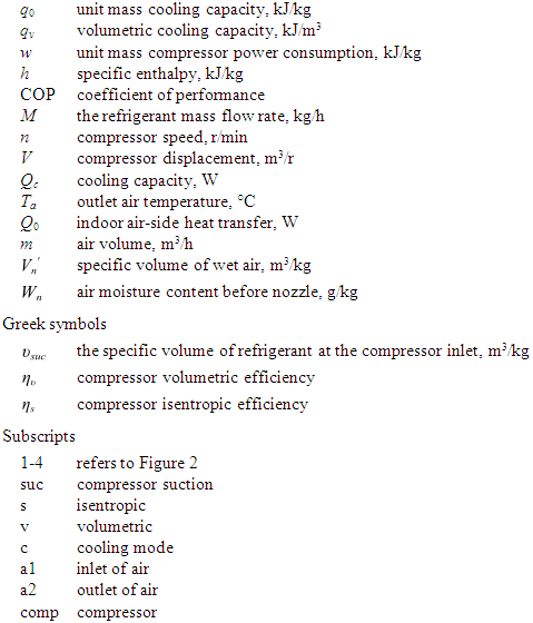
Nomenclature
References
| [1] | B. Pitiruţ, C. Ogunbode, V. Enea, Attitudes towards global warming: The role of anticipated guilt and the Dark Triad traits, Personality and Individual Differences. 185(2022) 111285. |
| [2] | L.F. Shi, S.N. Lv, C.X. Liu, et al., A framework for electric vehicle power supply chain development, Utilities Policy. 64 (2020) 101042. |
| [3] | J.D. Cao, X. Chen, R. Qiu, et al., Electric vehicle industry sustainable development with a stakeholder engagement system, Technology in Society. 67 (2021) 101771. |
| [4] | B.E. Lebrouhi, Y.Khattari, B.Lamrani, et al., Key challenges for a large-scale development of battery electric vehicles: A comprehensive review, Journal of Energy Storage. 44 (2021) 103273. |
| [5] | J. Lindgren, P.D. Lund, Effect of extreme temperatures on battery charging and performance of electric vehicles, Journal of Power Sources. 328 (2016) 37-45. |
| [6] | K.R. Kambly, T.H. Bradley, Estimating the HVAC energy consumption of plug-in electric vehicles, Journal of Power Sources. 259 (2014) 117-124. |
| [7] | Z.G. Qi, Advances on air conditioning and heat pump system in electric vehicles–A review, Renewable and Sustainable Energy Reviews. 38 (2014) 754-764. |
| [8] | H. Rezaei, M.J. Ghomsheh, F. Kowsary, et al., Performance assessment of a range-extended electric vehicle under real driving conditions using novel PCM-based HVAC system, Sustainable Energy Technologies and Assessments. 47 (2021) 101527. |
| [9] | Z. Yang, B. Feng, H.Y. Ma, et al., Analysis of lower GWP and flammable alternative refrigerants, International Journal of Refrigeration. 126 (2021) 12-22. |
| [10] | H. Li, K. Tang, A comprehensive study of drop-in alternative mixtures for R134a in a mobile air-conditioning system, Applied Thermal Engineering. 203 (2022) 117914. |
| [11] | Y.B. Wang, J.Q. Dong, S.W. Jia, et al., Experimental comparison of R744 and R134a heat pump systems for electric vehicle application, International Journal of Refrigeration. 121(2021) 10-22. |
| [12] | M. Yang, H. Zhang, Z.F. Meng, et al., Experimental study on R1234yf/R134a mixture (R513A) as R134a replacement in a domestic refrigerator, Applied Thermal Engineering. 146 (2019) 540-547. |
| [13] | J. Sun, W.H. Li, B.R. Cui, Energy and exergy analyses of R513A as a R134a drop-in replacement in a vapor compression refrigeration system, International Journal of Refrigeration. 112 (2020) 348-356. |
| [14] | Z.F. Meng, H. Zhang, M.J. Lei, et al., Performance of low GWP R1234yf/R134a mixture as a replacement for R134a in automotive air conditioning systems, International Journal of Heat and Mass Transfer. 116 (2018) 362-370. |
| [15] | A. Mota-Babiloni, P. Makhnatch, R. Khodabandeh, et al., Experimental assessment of R134a and its lower GWP alternative R513A, International Journal of Refrigeration. 74(2017) 682-688. |
| [16] | J.K. Vaghela, Comparative evaluation of an automobile air - conditioning system using R134a and its alternative refrigerants, Energy Procedia. 109 (2017) 153-160. |
| [17] | X.W. Chen, K. Liang, Z.H Li, et al., Energy and exergy analysis of domestic refrigerators using R152a to replace R134a, Thermal Science and Engineering Progress. 29 (2022) 101235. |
| [18] | B.O. Bolaji, Experimental study of R152a and R32 to replace R134a in a domestic refrigerator, Energy. 35(9) (2010) 3793-3798. |
| [19] | D. Sánchez, R. Cabello, R. Llopis, et al., Energy performance evaluation of R1234yf, R1234ze(E), R600a, R290 and R152a as low-GWP R134a alternatives, International Journal of Refrigeration. 74 (2017) 269-282. |
| [20] | X.W. Chen, K. Liang, Z.H. Li, et al., Experimental assessment of alternative low global warming potential refrigerants for automotive air conditioners application, Case Studies in Thermal Engineering. 22 (2020) 100800. |

 Abstract
 Reference
 Full-Text PDF
 Full-text HTML