-
Paper Information
- Paper Submission
-
Journal Information
- About This Journal
- Editorial Board
- Current Issue
- Archive
- Author Guidelines
- Contact Us
Journal of Mechanical Engineering and Automation
p-ISSN: 2163-2405 e-ISSN: 2163-2413
2021; 10(2): 25-35
doi:10.5923/j.jmea.20211002.01
Received: Sep. 17, 2021; Accepted: Sep. 24, 2021; Published: Oct. 15, 2021

Development of Data-Driven Digital Twin for Real-Time Monitoring of FDM 3D Printer
 Abstract
 Reference
 Full-Text PDF
 Full-text HTML
Charles A. Odada1, Jean B. Byiringiro2, Fredrick M. Madaraka3
1Department of Mechatronic Engineering, Dedan Kimathi University of Technology, Dedan Kimathi, Kenya
2Siemens Training Centre, Dedan Kimathi University of Technology, Dedan Kimathi, Kenya
3Department of Mechanical Engineering, Dedan Kimathi University of Technology, Dedan Kimathi, Kenya
Correspondence to: Charles A. Odada, Department of Mechatronic Engineering, Dedan Kimathi University of Technology, Dedan Kimathi, Kenya.
| Email: |  |
Copyright © 2021 The Author(s). Published by Scientific & Academic Publishing.
This work is licensed under the Creative Commons Attribution International License (CC BY).
http://creativecommons.org/licenses/by/4.0/

Fused deposition modelling (FDM) and digital twinning are considered important areas to the future of manufacturing. However, both technologies still face major challenges to their adoption. Errors in printed products are still common in FDM, while cost and gaps in knowledge and technology have made digital twins inaccessible for many. This paper presents the design and use of a data-driven digital twin of an FDM 3D (three dimensional) printer that was used to monitor the motions of a 3D printer in real-time. Sensors attached to the physical 3D printer were used to gather motion data for the virtual 3D printer modelled in Siemens NX. Communication to the virtual printer was handled by a Modbus server and an OPC-DA (Open Platform Communications—Data Access) server. Tests were performed to evaluate the virtual 3D printer’s ability to monitor the real 3D printer’s movements in real-time, the relationship between the printer’s motions and the generated vibration signals, and the digital twin’s ability to repeat the motions from past printing sessions using logged data (history tracking). The results showed that a virtual 3D printer can be used to monitor the motions of an FDM 3D printer in real-time with a maximum average time lag of 0.351 seconds. The vibration patterns generally reflected the state of the physical system. Lastly, the history tracking feature was able to repeat the motions from previous printing sessions using the logged data but introduced some extra lag.
Keywords: Digital twin, 3D Printer, Real-time monitoring, Arduino, History tracking, Industrie 4.0, Virtual printer, Motion tracking
Cite this paper: Charles A. Odada, Jean B. Byiringiro, Fredrick M. Madaraka, Development of Data-Driven Digital Twin for Real-Time Monitoring of FDM 3D Printer, Journal of Mechanical Engineering and Automation, Vol. 10 No. 2, 2021, pp. 25-35. doi: 10.5923/j.jmea.20211002.01.
Article Outline
1. Introduction
- Fused deposition modelling (FDM) 3D printers became popular due to their relative affordability. These types of 3D printers can be used for production of functional parts at a low cost from thermoplastic filaments [1]. Digital twins, on the other hand, are considered an essential part of industrie 4.0. These virtual representations of real-world entities use data from different sources to improve, among other things, the monitoring and control of their physical counterparts [2]. Digital twinning is expected to help many factories to switch to smart manufacturing, and experts in healthcare, urban planning and other fields also predict that this technology could have a significant impact in their industries [3].Digital twins’ data driven approach also provides a means through which machine learning and artificial intelligence could be integrated into industrial machines and systems in the future [4].
1.1. State of the Art of FDM 3D Printing Technology
- Fused deposition modelling or FDM is an additive manufacturing process that is classified under material extrusion processes. These technologies are used for quick production of prototypes and functional parts. They are able to handle new and complex designs which cannot be manufactured easily using traditional methods [5].There are different types of 3D printers that use FDM technology. These printers make use of different mechanisms to produce the final products. The following are some of the currently available FDM 3D printers in the market:• Cartesian printers: The printing position in these printers is attained by moving the printhead and the print bed in straight lines along the three main axes of the Cartesian plane [6].• Delta printers: The print head is moved to the correct printing position by three arms, each attached to a runner that only moves vertically. These printers use trigonometric calculations to determine the positions of the runners needed to attain the required printhead positions [7].• Polar printers: According to O’Connell [6], these printers use a polar coordinate system, i.e., a circular grid, to establish the printing position. These printers have rotating print beds and the printheads are typically attached to curved swinging arms.• Selective Compliance Assembly Robot Arm (SCARA) printers: The printhead is connected to a robotic arm in these printers. They also use the Cartesian coordinate system, but their mechanism makes them quite distinct compared to other FDM 3D printers that use the same coordinate system [6].• CoreXY and HBot printers: These two FDM printer types are quite similar as they both make use of complex pulley and belt systems to move the printhead on two axes at the same time. Both printer types have print beds that move along the Z-axis. However, the belt systems used for these printers are different [6].The different FDM 3D printing mechanisms each have their advantages. Delta printers can print at faster speeds than Cartesian printers while polar printers operate with fewer motors. SCARA systems can print much larger items than other printers, and CoreXY printers are more stable compared to normal cartesian printers. However, Cartesian printers are simpler to develop and troubleshoot. There is also a large community built around Cartesian 3D printers. This makes it easier to find solutions to many challenges [6]. As Schmitt et al. [8] pointed out, Cartesian printers were the most common in the market. The relatively complex systems used by other FDM 3D printers, coupled with cost and availability issues, made a Cartesian printer the ideal choice for this study.A Cartesian FDM 3D printer consists of an extruder mounted to a Cartesian robot as shown in Figure 1. The extruder heats and extrudes the raw material onto a print bed while moving in the X and Z direction. The print bed moves in the Y direction only [9].
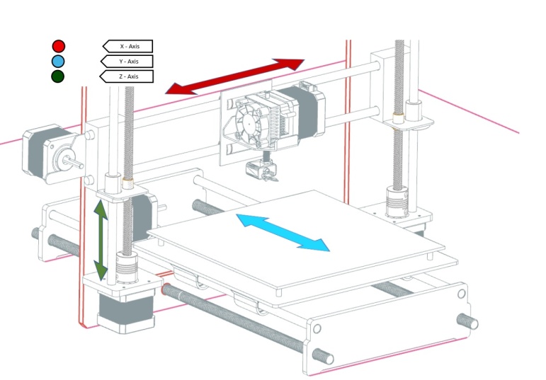 | Figure 1. Illustration of direction of motions of a typical Cartesian 3D printer |
1.2. Developing a Digital Twin
- Digital twins are the result of years of development of different virtual systems. These systems included, simple simulations, personnel training systems and complex predictions systems [16]. Jones et al. [17] stated that a digital twinning system needs a physical entity, a virtual model, and a means of transmitting data between the two. The system had to have a set of processes capable of being carried out by both the physical and virtual twin. The system also required measurable characteristics that could be used to define the state of the system at a given moment. The rate at which the two systems were synchronised, or "twinning rate", also had to be measurable [17].Different technologies must be used together to create digital twins that meet these characteristics [18]. Apart from the challenge of merging different technologies to form a single system, Deloitte [19] identified the choice of an ideal level of detail for a digital twin as a major challenge that must be handled early. A system that was too simple would not have much value, but one that was too complicated would be difficult to make sense of. According to Smajic et al. [20], virtual systems should only be as accurate as necessary due to the current limitations of simulations.Deloitte [19] recommended the approach illustrated in Figure 2 towards the development of digital twins. The development starts with identification of an entity that would benefit from twinning. A specific process within it is chosen to serve as a pilot before expanding to others. The pilot program should move quickly so that lessons can be learnt quickly and the correct approach to the twinning process identified early. This would enable the program to move faster to the mainstreaming stage. This would get the benefits of twinning to other parts of the entity and quicken the process of scaling. The successful twin should also be monitored further to identify potential areas of improvement [19].
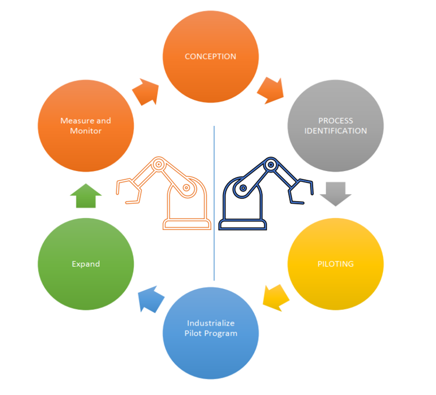 | Figure 2. Recommended process for digital twin development |
1.3. State of Art of Digital Twinning of FDM 3D Printers
- According to Chhetri et al. [22], development of a digital twin for manufacturing systems has been attempted for a long time. Various studies in the past have made notable contributions towards the realisation of a fully functional digital twin for an additive manufacturing system. These contributions were in the development of architectures, instrumentation and computational models.Debroy et al. [23] discussed what it would take to achieve a digital twin that could help to improve the internal characteristics of 3D printed metal components. However, they acknowledged that the technology needed to achieve this level of control was still in the development stages. Mukherjee and DebRoy [24] also showed how a digital twin could improve the speed at which 3D printed metal parts were qualified and reduce the need for trial-and-error tests. However, they pointed out that major technological advancements were still needed before such a digital twin could become a reality.Chhetri et al. [22] used analog emissions to demonstrate how a digital twin and machine learning could be used to predict certain performance indicators when 3D printing. The focus of their approach was prediction of specific characteristics of the printed model using non-invasive data acquisition methods. Real-time monitoring of the physical printer’s movements was not tested. Using the same principle of inferring the state of the printer from acoustic signals generated by the moving parts, Kubiak et al. [25] demonstrated that it was possible to reconstruct the shape of a printed model using only analog emissions.Li et al. [26] demonstrated the importance of remote monitoring of 3D printing operations. They used the OctoPrint application to monitor the performance of a 3D printer. The application provided the users with information on the temperatures of the hot end and heated bed. The printing process could also be followed visually thanks to a video feed. Delli and Chang [27] demonstrated how image processing and machine learning could be combined to detect defects in 3D printing. This approach required pausing of the printing process for the image to be taken, and it could only detect defects visible from the top due to the use of only one camera.Knapp et al. [28] proposed and validated a model for developing a digital twin for directed energy deposition 3D printing methods. Once realised into a functional digital twin, the proposed model was expected to limit the need for empirical testing by offering accurate predictions of various parameters. The model was also expected to utilise computational resources efficiently.Yang et al. [29] pointed out that limited knowledge of additive manufacturing processes resulted in predictive models that were limited to specific experimental conditions. They utilised a new meta-modelling method, grey-box modelling, to develop a better predictive model for the powder bed fusion 3D printing method. Challenges in data collection was identified as one of the reasons behind a lack of empirical data regarding additive manufacturing processes.Mennenga et al. [30] presented an approach for combining Cyber-Physical Production Systems and Product-Service systems. Using a 3D printing case study, the developed architecture would aggregate process data and energy use data into a cloud computing environment. The data would then be analysed to enable service providers to identify their users’ needs. Thereafter, they could help the end users to get better results from their 3D printers and improve the machines’ durability, while also reducing their environmental impact.There have been many development efforts that have gone into realising digital twins and other cyber-physical systems for additive manufacturing processes. Due to technical limitations and other reasons, many of the proposed approaches are yet to realise fully functional systems. This paper presents the design and use of a data-driven digital twin of an FDM 3D printer. Invasive methods were used to monitor the motions of a physical 3D printer in real-time and motions from past printing sessions were also simulated on the virtual printer. The digital twin utilised the motion data with a physics-based model to simulate the operation of an FDM 3D printer, and this allowed further examination of motion-related parameters, i.e., speed and vibrations.
1.4. Significance of Motion Tracking in FDM 3D Printing
- Motion tracking of 3D printers can be a useful feature for analysing the performance of the machine. Kubiak et al. [25] showed that it was possible to reconstruct printed shapes if the movements of the print head were known. Therefore, if the motion data is accurate, it can be used to check if the model being printed has the necessary dimensional accuracy. The positions of the print head and print bed can be compared to their expected positions from the G-Code at any moment. Identifying dimensional inaccuracy early can help to reduce the wastage in 3D printing that was discussed by Zhang et al. [31].According to Kondo [32], 3D printing can take several hours to produce a single model. Although it is possible to adjust the printer’s speed settings to improve this, this could also lead to print failure. Pilch and Szlapa [33] already demonstrated that increasing the speed of 3D printing above certain values caused significantly higher levels of vibrations. Therefore, it may be possible to optimise printing speeds by first testing the effects of different printing speeds on vibrations and other parameters on a physics-based model.Applications such as Octoprint have demonstrated their usefulness in remote monitoring of 3D printing operations. This application enables users to remotely view the printing operation through a video feed [26]. However, as pointed out by Ahmed et al. [34], transmission of video signals over the internet requires a high data rate to attain the right service quality. The amount of bandwidth needed to handle a short video could handle a larger amount of text [35]. The motion data can simply be a series of Z, Y and Z positions, and this can also be bundled with other textual data from the physical printer. If the data is transmitted to a remote system that is designed to process and display it, e.g., a virtual 3D printer, real-time monitoring of the printer can be achieved with less bandwidth compared to video streaming. In some cases, multiple 3D printers are used on a production scale [27]. In such situations, use of video to monitor every printer may exceed the bandwidth of the network.Chhetri et al. [22] demonstrated how machine learning and acoustic sensors could be used for error detection in 3D printing. The modelled digital twin used relied on side-channels rather than data gathered directly from the printer. A digital twin that combined these error detection features with accurate motion tracking would know the exact positions of the moving parts when an error was detected. The region affected by an error could be identified instantly. In the future, the 3D printer may even be able to correct the detected errors immediately before continuing on its printing path.
2. Methodology
- To develop the data-driven digital twin, a physical 3D printer, a virtual 3D printer and a system to handle communication between the two were needed. A system for logging data and feeding it to the virtual printer later was also needed to create the history tracking feature.The virtual FDM 3D printer was modelled using the Siemens NX software. The physics characteristics and signal receptors of the model were defined using the Mechatronics Concept Designer (MCD) application. Three optical rotary encoders were added to the physical printer to register motions. A Modbus server was set up on an Arduino Mega microcontroller to collect the encoder data. Communication between the Modbus server and the virtual printer was handled by an OPC-DA server set up in Kepserverex. The data was also logged to MS Access using Kepserverex’s logger. Finally, using the Dynamic Data Exchange (DDE) driver in Kepserverex, MS Excel was linked to MCD to enable history tracking/analysis.The software was running on a System76 Oryx Pro laptop with an Intel i7-7820HK processor. The computer also had an 8-gigabyte NVIDIA GTX 1070 GPU and 16 gigabytes of RAM.
2.1. The Physical System
- The 3D printer used for this study was the GEEETECH Aluminum Prusa I3. This is a Cartesian printer with an extruder that moves in the X and Z directions and a print bed that moves in the Y direction only. The choice of this printer was determined by two main factors:1. Open Design: The open design of the GEEETECH printer made it easier to attach the sensors used to collect position data. Finding ideal locations to attach rotary encoders would be a challenge if the 3D printer had an enclosure due to the size of the encoders.2. Aluminium Frame: The printer’s aluminium frame made it more robust compared to printers with acrylic frames. The weight of two of the rotary encoders were completely supported by the printer. This added weight might have significantly impacted the performance of a 3D printer with a weaker or lighter frame.Three optical rotary encoders were used to get the position data from the physical printer. Each encoder had a resolution of 600 pulses per revolution (PPR). The final set up is shown in Figure 3 (a) and (b).
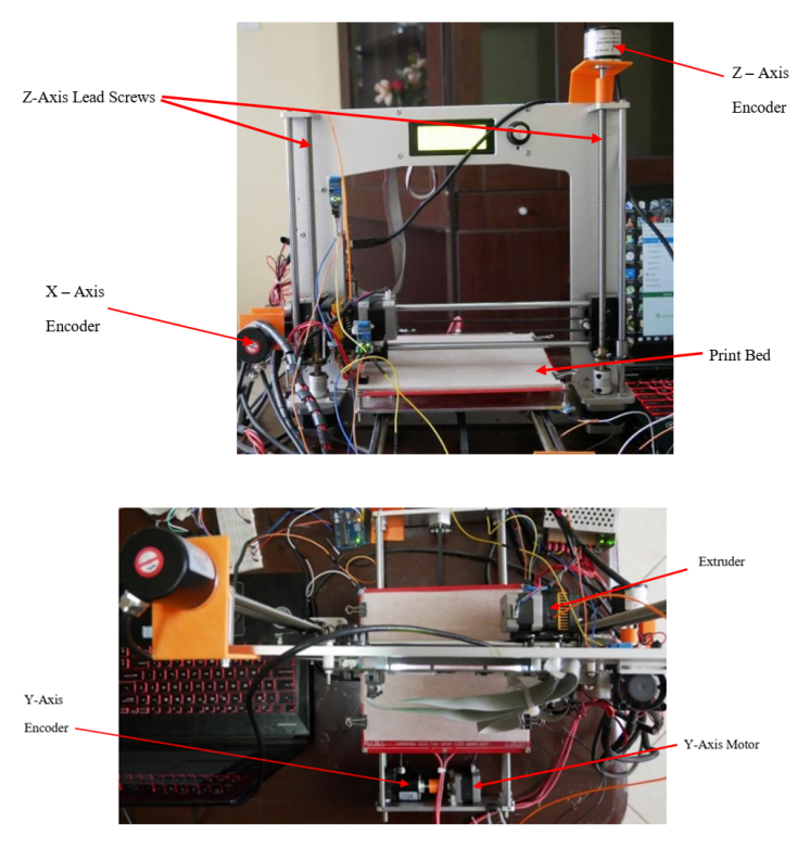 | Figure 3. (a) Front view of the Geeetech Aluminium Prusa i3 with encoders, (b) Top view of 3D printer with encoders |
2.2. Communication Systems
- A single stage communication system was not possible for this digital twin due to software/hardware compatibility issues. Therefore, the communications system was set up by linking a Modbus server and an OPC-DA server.
2.2.1. Modbus Server
- The Modbus server was set up on an Arduino Mega microcontroller. The Modbus server could receive data from the encoders and make it available to other servers and clients as needed. The Arduino Mega was chosen because it has six interrupt pins. Each encoder required two interrupt pins on the microcontroller.
2.2.2. OPC-DA Server
- The OPC-DA protocol was chosen because Siemens NX has inbuilt features that make it easy to link this type of server with the MCD. The server was set up using the Kepserverex Software. Formulas were added to convert the number of pulses into millimetres as required by the virtual printer. The OPC-DA server was set up to scan for new data on the Modbus server every 10 milliseconds. This was the fastest possible setting.
2.3. The Virtual Model
- The virtual 3D printer was mostly modelled in Siemens NX (Siemens Product Lifecycle Management (PLM) Software, Plano, TX, USA), a powerful computer aided design (CAD) modelling software. The MCD comes bundeled together with Siemens NX. As shown in Figure 4, the virtual model needed to have the essential features of the physical printer. It also needed to be able to mimic the main motions of the physical printer during printing. Some of the parts used in the model, including the extruder assembly, were acquired from GrabCAD.
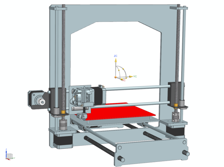 | Figure 4. The virtual printer assembled in Siemens NX |
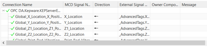 | Figure 5. Mapping of signals between Kepserverex and Mechatronics Concept Designer (MCD) |
2.4. Digital Twin Architecture
- The data flow chart for the system is shown in Figure 6(a). Figure 6(b) shows how the digital twinning system could influence how users made decisions. The position data could be accessed by the virtual model in either real-time (RT) mode or History Tracking (HT) mode. However, vibration data was only sent to the virtual printer in HT mode. When the simulation was running, any movement by the physical printer in the X, Y or Z direction was to be replicated by the digital twin in real-time. If a model was sent to the physical printer to be printed, the virtual model was expected to mimic the motions of the extruder and the print bed in real-time and in the correct sequence. The virtual twin was not expected to produce a virtual copy of what the physical printer was printing due to software limitations. Kepserverex would also be logging the data coming in from the physical printer for use in history tracking.
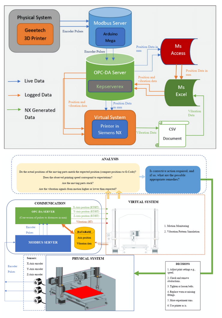 | Figure 6. (a) Data Flow Chart for the Digital Twinning System, (b) Application of Proposed Digital Twin to influence printing process |
3. Results
3.1. Quantitative Motion Study
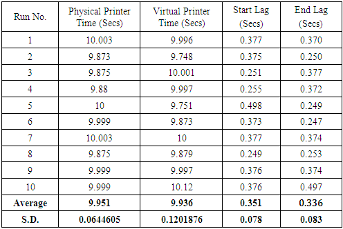
- A real-time motion study was carried out to determine the lag in the response of the virtual printer compared to the physical printer’s movements. The time lag at the start and end of each experiment was noted. A command was sent to the physical printer to move the extruder 50 mm. A camera and a millisecond timer were used to capture the moment both printers set off and when they stopped. The results from the 10 experimental runs are shown in Table 1.
|
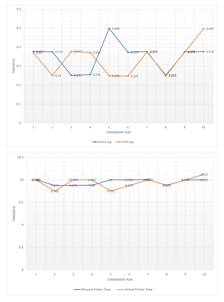 | Figure 7. (a) Graph comparing lag at the start of the experiment to the lag at the end, (b) Comparison of time taken by physical printer |
3.2. Qualitative Motion Study
- This analysis was performed to determine whether there were any observable differences in the quality of motion between the physical and virtual printers. The motions of the virtual twin were smooth, and it kept up with the physical printer most of the time with only the lag discussed above. However, in certain instances, the virtual printer paused for brief moments before skipping ahead to catch up with the physical printer. This was seen during short and fast movements with rapid changes in direction and other instances.When moving parts were obstructed, the corresponding parts in the virtual printer were also affected.For this analysis, it was also necessary to analyse whether the data generated by the virtual printer corresponded with what was expected from the physical system. This assessment was carried out by observing the motions of both printers in real time and comparing them to the vibration pattern that was generated at the same time by the virtual printer, as seen in Figure 8.
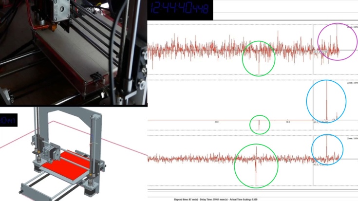 | Figure 8. Comparison of Printer Motions to Generated Vibration Data |
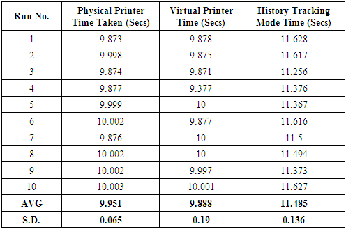
3.3. History Tracking
- To enable history tracking, positional data was logged from the physical printer during a typical printing operation. This was done using Kepserverex’s data logger and an MS Access database. The data was exported onto an MS Excel spreadsheet that was programmed to go through the data in the order and rate that it was logged. Kepserverex’s DDE driver was then used to access the data in excel, allowing the same data to be accessed by the MCD in Siemens NX.The experiment used to determine time lag was repeated with the data being logged. The data was then used to run the virtual 3D printer. The total time taken to complete the 50 mm run was the main focus this time. The results are shown in Table 2. The average finish time was 11.485 seconds with a standard deviation of 0.136.
|
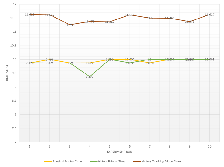 | Figure 9. Comparisons of completion times between the different operating modes |
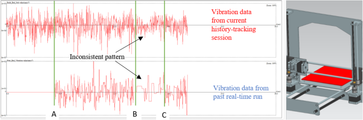 | Figure 10. Virtual twin running in history tracking mode with vibration data generated from print |
4. Discussion
- The results from the experiments showed that real-time tracking of the movements of a 3D printer was possible with a minimal amount of lag. A certain amount of lag was always expected because transmission of data is not instantaneous. However, to improve fidelity, it would be beneficial to investigate ways of further lowering the lag. There was no obvious reason behind the brief pauses observed in the virtual 3D printer during the qualitative motion study. It was also observed that this phenomenon became more frequent when data logging was taking place. One possible reason for this was data loss arising from Kepserverex’s 10 ms scanning rate. This scanning rate meant that if data in the Modbus server changed faster than Kepserverex could keep up, the data would be replaced before the virtual printer acquired that position. However, the increased occurrence of the issue when data was being simultaneously logged points to a possible processing or software issue. It is likely that the increased demand on the system overwhelmed either the processor or Kepserverex. Should future versions of Kepserverex permit faster update rates, it may improve the fidelity of motion observed, but other possibilities should be investigated as well. A better analysis of the results will also be possible if the virtual 3D printer can be programmed to produce a product based on its movements.There was also no obvious cause for the difference in lag between the start and end of the experimental runs. It is possible these differences were merely the result of errors in the data capture hardware and software, i.e., the recording frame rate and software timer errors. The camera used had a maximum frame rate of 60 frames per second, and the timer’s resolution was also in the range of 100s of milliseconds. These two factors meant that it was often difficult to identify the exact moment the motion started.The correlation between the vibration patterns generated by the virtual printer and the motions of the physical 3D printer means that the system can be useful in assessing the effects that the printer’s motion could have on various parameters. However, more research is still needed to assess the consistency and reliability of the data generated.The history tracking feature could be useful in analysing the behaviour of the 3D printer in the long run. However, more research will be needed before this tool can be properly utilised. The speed of the virtual printer was dependent on the rate at which the data was logged. Data logged at higher rates, e.g., 10 ms resulted in extremely slow movements, hence the need to use data logged at 100 ms. The same slow movement was seen when the laptop used was running on battery power alone. Further research is needed to establish whether the system will benefit from a computer that will allow an even greater power draw or one with a better central processing unit (CPU)/graphics processing Unit (GPU).There was still a significant lag when operating the virtual printer using data logged at a rate of 100 ms. Apart from the effect of this lag on the observed motion, it may also be one of the reasons behind differences in vibration patterns generated during the history tracking session. The discrepancy pointed out in Figure 9 between sections B and C illustrates this problem. The two sections should have been identical since the data used to generate the motions was the same. Therefore, the earlier identified lag probably resulted in the two vibration patterns being at different points in printing time.In addition to the issues discussed above, this approach has a number of limitations that will affect where and how it can be used unless significant changes are made. The most notable of these limitations are:1. Printer Type: While the overall architecture could be used on another FDM 3D printer, this study used a Cartesian FDM 3D printer. The simple correlation between the movements of the motors and the directions of motion made it simpler to define how the signals affected the model. The motions of FDM 3D printers that are not Cartesian may be harder to accurately model due to the more complex relationships between the motors and the motions of the print bed and extruder.2. Printed Product: The absence of a printed product from the virtual printer makes it harder to make comparisons between the two printers and analyse dimensional errors and other parameters.The results of this study showed that much can be done with regards to development of digital twins using technology that is already available. Many aspects of digital twins for additive manufacturing systems cannot be achieved in the present due to technological gaps. However, the approach used in this study demonstrated that the tools exist to create other parts of these digital twins. The history tracking feature, for instance, only required the addition of MS Access and MS Excel to the system. Despite its simplicity, it was able to serve as a means of ensuring the data captured from the printer and that generated by the virtual printer could be stored and replayed. This would not only offer a glimpse into the machine’s past activities but also a means of comparing changes in operation.This study also demonstrated that a digital twin can be an effective tool for monitoring the operation of an FDM 3D printer. The digital twin in this study was able to keep up with the actual 3D printer during the printing process, making it possible to track the moving parts of the machine at any given moment. This opens up an alternative avenue for remote monitoring of 3D printers that will utilise less bandwidth.The study also showed that a physics-based model could be a vital part of future digital twins for FDM 3D printers. The generated data (vibrations) from the model reflected what was expected from the physical system. Therefore, when working with physics-based models, certain characteristics can be inferred based on others. If validated, this would reduce the need to have sensors to capture every parameter needed from the physical 3D printer.Although cost has been a major concern in the development of digital twins, this study demonstrated that there is a place for inexpensive approaches to digital twin development. Siemens NX was the most expensive part of the developed system. However, the same software is already available in many learning institutions and other organisations for other purposes. Less costly digital twins will be important to justify early development efforts, especially in fields such as additive manufacturing that are still maturing.The position data used to move the virtual printer could also be used to form a copy of the product being printed in real-time in the virtual world. This same data, if compared to the G-Code, could inform users whether the printed product’s dimensions were consistent with what was expected. It could also make remote monitoring of 3D printers using digital twins simpler. This would be an ideal next step for this research.This study was only a first step and further research will be necessary to improve the fidelity of the digital twin. More sensors, e.g., tilt sensors, will make asset instances more accurate. The data from physical vibration sensors will also be needed to validate the data generated by the physics-based model. The source of the lag and sudden pauses in the system should also be established and eliminated if possible. Future designs should also explore ways of connecting the encoders to the belts and not the motors. This will ensure belt skipping is also registered by the virtual printer.
5. Conclusions
- The ability to comprehensively monitor the behaviour of a machine such as an FDM 3D printer can help to improve users’ understanding of such machines and the factors that affect their performance. Digital twinning technology makes it possible to monitor machines to a greater degree, but their implementation can be time and money consuming. In this paper, a simple and inexpensive digital twinning system was developed for an FDM 3D printer. The system consisted of a virtual model of an FDM 3D printer linked to the physical printer via an Arduino Modbus server and an OPC-DA server on Kepserverex. The virtual 3D printer was able to follow the motions of the main parts of the physical 3D printer in real-time, with a lag of less than half a second. Using tools provided in Siemens NX, the user was able to extract additional information about the printing process from the virtual printer, e.g., vibrations in different printer parts and compare their correlation with observed motions. Additionally, using MS Excel and Kepserverex’s DDE driver and data logger, a history tracking tool capable of running simulations of past printing operations was developed. This made it possible to get new data about past printing sessions and to compare data sets generated at different times in Siemens NX. Future steps in this research will be to investigate the cause(s) of this digital twin’s shortcomings, to introduce additional data from the physical printer and to add a feature that will produce a virtual copy of the printed product based on the virtual printer’s movements and enable comparisons with the initial CAD model.
ACKNOWLEDGEMENTS
- Acknowledgments: This research was carried out with the assistance of Dedan Kimathi University of Technology (DeKUT)-Kenya, Mechatronics Department which provided the software required to carry out this research. The code used to set up the Arduino Modbus server was adapted from examples in the Arduino Modbus Remote Terminal Unit (RTU) Slave library by BrewTroller and the Encoder.h library. Several parts of the assembled model used were acquired from Grabcad members including Marijo Blazevi´c (extruder assembly), Sam Fisher (linear bearings), Lehavier (timing pulley), Andrey Nesterov (lead screws and lead screw nuts), and Happysoft (flexible couplings).