-
Paper Information
- Paper Submission
-
Journal Information
- About This Journal
- Editorial Board
- Current Issue
- Archive
- Author Guidelines
- Contact Us
Journal of Mechanical Engineering and Automation
p-ISSN: 2163-2405 e-ISSN: 2163-2413
2021; 10(1): 19-23
doi:10.5923/j.jmea.20211001.03
Received: Jul. 10, 2021; Accepted: Aug. 6, 2021; Published: Aug. 15, 2021

Analysis the Occurrence of Wear on Crank Pin Bearing in Diesel Engine
 Abstract
 Reference
 Full-Text PDF
 Full-text HTML
Didit Sumardiyanto, Sri Endah Susilowati
Department of Mechanical Engineering, 17 Agustus 1945 University, Jakarta, Indonesia
Correspondence to: Didit Sumardiyanto, Department of Mechanical Engineering, 17 Agustus 1945 University, Jakarta, Indonesia.
| Email: |  |
Copyright © 2021 The Author(s). Published by Scientific & Academic Publishing.
This work is licensed under the Creative Commons Attribution International License (CC BY).
http://creativecommons.org/licenses/by/4.0/

This research was conducted on the HANSHIN type LH36L engine which is the main engine of MV. Poertocurtis. This research was triggered by the emergence of disturbances in the form of vibrations on the machine. In connection with these conditions, it is necessary to conduct research to determine the source of the problem so that the same condition does not recur in the future. The method used in this research is to dismantle the generation of elements and measure the mass of each element needed for calculations. The data obtained in the field, assuming a maximum load of 130% of the engine output power, shows that the maximum effective power, Ne is 2 486 kW, indicated power Ni is 2 825 kW, and indicated pressure, Pi is 307 N/cm2. The thrust of the piston, Fgh is 552 640 N, the reciprocating inertia force, Fj is 62 316 N, the total force received by the piston pin, Fsum, and the force received by the crank pin, Fcr is 616 780 N, the average plane pressure journal kmax is 162.5 kg/cm2, and the working bearing characteristics, λcr is 58.15, which is still below the tolerance limit. So that the wear of the crank pin bearing that occurs on the main engine MV. Poertocurtis is caused by impurities in the form of combustion carbon that enter the lubricating crankcase.
Keywords: Wear, Crankpin, Diesel engine, Lubrication
Cite this paper: Didit Sumardiyanto, Sri Endah Susilowati, Analysis the Occurrence of Wear on Crank Pin Bearing in Diesel Engine, Journal of Mechanical Engineering and Automation, Vol. 10 No. 1, 2021, pp. 19-23. doi: 10.5923/j.jmea.20211001.03.
Article Outline
1. Introduction
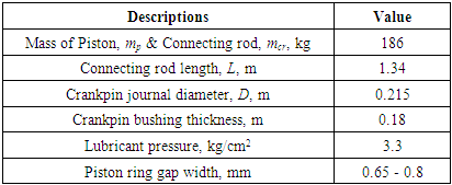
- This research was conducted due to the occurrence of vibration which is quite disturbing in the operation of the diesel engine for the main propulsion of a ship. It is feared that this condition will cause greater damage in the future. Related to these conditions, an overhoul is carried out to check the elements in the power generation mechanism. The results of the inspection show that there is wear on the surface of the crankpin bearing. The diesel engine is a piston type internal combustion engine where fuel ignition is caused by the high temperature of the combustion air in the combustion chamber which reaches 550°C due to a large compression ratio, which is between 14:1 to 25:1, which provides a final compression pressure of up to 40 bar. . Because the final combustion pressure is very high, the thrust transmitted by the piston is also large. The crankshaft is a power generating element that converts the translational motion of the piston transmitted by the connecting rod into rotational motion which is then used to rotate the other engine shafts. While the crank pin bearing is the place where the crankshaft and connecting rod are connected, so that the load it receives is very large.The research on the causes of damage to the crank pin bearing was carried out using theoretical basics about the distribution of forces on the power generation mechanism in a piston combustion engine.In some studies it was reported that abnormal noises can be produced by worn crank pin bearings [9,10]. There are indications that bearing failure can be caused by poor lubrication, for example insufficient amount of lubricant so that it cannot enter the gaps of the parts to be lubricated, or also due to dirt mixed in the lubricant causing erosion of the bearing walls [11]. Bearing failure can also occur due to overload so that the lubricant layer is not able to support the received load, and another possibility is the occurrence of hot rodding. From the results of this research, it can be concluded that the cause of damage to the crank pin bearing can be drawn.
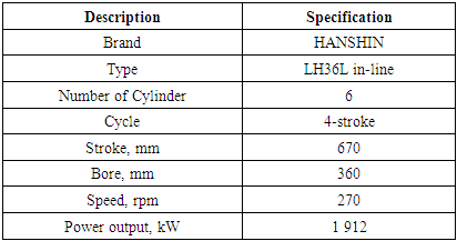
2. Specifications
- In this researc, the ship used the main propulsion Hanshin diesel engine, LH36L in-line, with general specifications as shown in Table 1.
|
|
3. Result and Discussions
- The calculation is carried out based on the thrust from the piston due to receiving pressure from the combustion results in the combustion chamber, which is forwarded by the connecting rod, to be converted into torque on the crankshaft [11].
3.1. Maximum Effective Power
- Effective power is the real power that can be produced from a machine to be used for various purposes. From the engine specifications, the effective power generated by the engine, Ne, is: 1 912 kW.In this calculation, the maximum effective power is based on 130% of the engine output power, so that:Maximum Effective Power, Ne.max,

3.2. Indicated Power
- Indicated power, Ni, is the power generated from the combustion process in the cylinder, the values are:

 : 2 486 kW
 : mechanical efficiency, for a 4-stroke engine with a turbocharger ranging from [11] 0.80 to 0.88, the maximum value is taken.Then:
3.3. Indicated Pressure
- Indicated pressure is the pressure in the combustion chamber due to fuel combustion, the value is
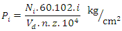 Pi: indicated pressure, kg/cm2Vd: volume of the piston stroke, m3D: 360 mmL: 670 mm
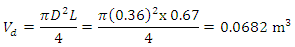
 : 270 rpm
 : 6
: 6  : cycle ratio, for a 4-stroke engine is 2So:
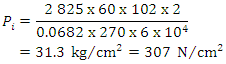
3.4. The Force Distribution
- Due to the pressure generated by the combustion of fuel in the combustion chamber, it produces thrust on the piston. Then the force is transmitted to the crankshaft through the connecting rod. Between the connecting rod and the crankshaft there is a bearing called the crank pin bearing which is the topic of this research. The distribution of forces on the power generating elements is as shown in Figure 1.
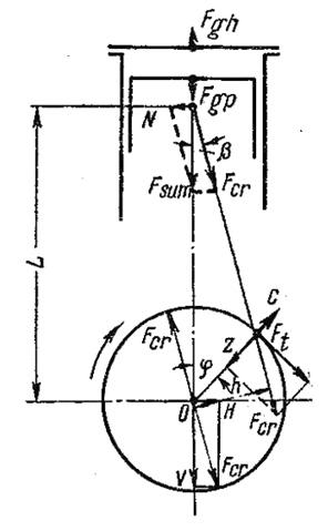 | Figure 1. Force distribution in the power engine generating [11] |
 Fgh: the force the piston receivesPgp: Pi-max: 307 N/cm2A: the cross-sectional area of the piston, D: 0.36 m: 360 mmThen
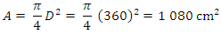 Fgh = FgpFgp: the force transmitted by the piston pin to the connecting rod
3.5. Reciprocating Inertia Force
- The basic theory to determine the value of the reciprocating inertia force is [11]:
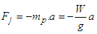 Fj: Reciprocating Inertia Force
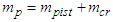 : 186 kg
 : total mass
 : mass of piston
 : mass of connecting rodPiston acceleration
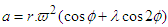
 : Piston acceleration, m/s2
 L: length of connecting rod: 1.34 m
  Crankshaft angular speed,
 So
So 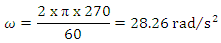
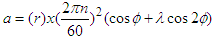
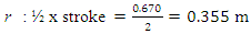
 : angle of movement of the crank
 So
So 
 : 0.355 m
 : 28.26 rad/s2Then:
 So reciprocating inertia force:
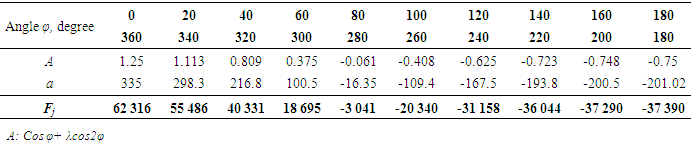
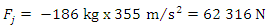 Furthermore, the results of the reciprocating inertia force, Fj, calculation for various angles are presented in Table 3.
|
3.6. The Overall Force Received by the Crankpin
- The overall force received by the crankpin is equal to the force received by the crank pin bearing
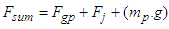 Fgp: 552 640 NFj: 62 316 N
 : 186 kg
 : 9.81 m/s2Then:Fsum = 552 640 + 62 316 + (186 x 9.81) = 616 810 N
 at maximum load
  The overall force received by the crankpin
 Then
Then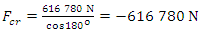 a negative sign ( - ) indicates the opposite direction The load (pressure) received by the crank pin bearings:
 Fcr: 616 780 NA: area of resisting force, d: 21.5 mm, L: 180.0 mm
 Pressure received:
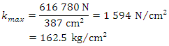 The results show that it is within the limits for the load on the crank pin bearings [4,355].Characteristics of Bearing Working Conditions
 : 270 rpm
 : dynamic viscosity SAE 10W-50, at temperature 60°C,
  kmax: 162.5 kg/cm2 Then the characteristic value of the bearing working condition is:
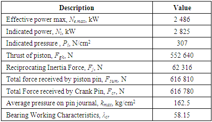
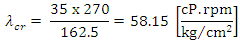 The values obtained are still within the characteristics of the bearing working conditions.Tabel 4 shows the results of the calculation of the forces on the power generating elements that occur due to the pressure received by the piston during the combustion process in the combustion chamber.
|
3.7. The Results of the Calculations are Obtained That
- a. The results of the calculation show that the damage to the crank pin bearing is not due to the magnitude of the force received by the bearing. This is evidenced by the value of the average field pressure received by the crank pin bearing, which is kmax: 99.4 kg/cm2. This value is still within the specified standard tolerance, which is 90 to 120 kg/cm2, and the characteristics of the bearing working conditions
 are also below the tolerance area, which is between 100 and 250
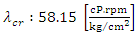
  .b. From observations in the field, it was found that there were deposits of dirt in the engine lubricating tub, as shown in Figure 2, which was in the form of a hard powder like sand that came from carbon. The material turned out to be the cause of the erosion of the bearing on the crank pin.c. Figure 3 is the result of several other studies on crankpin wear which show that combustion residues, water vapor, and other foreign substances produced during the combustion process of a diesel engine are the main impurities of lubricating oil. Secondary foreign substances can cause abrasion to machine parts and play a role in creating metal foreign substances. To prevent this wear, by removing foreign substances in the engine lubricating oil by optimizing the function of the lubricating filter.
 | Figure 2. The hardened powder is taken from the gap of the crank pin bearing |
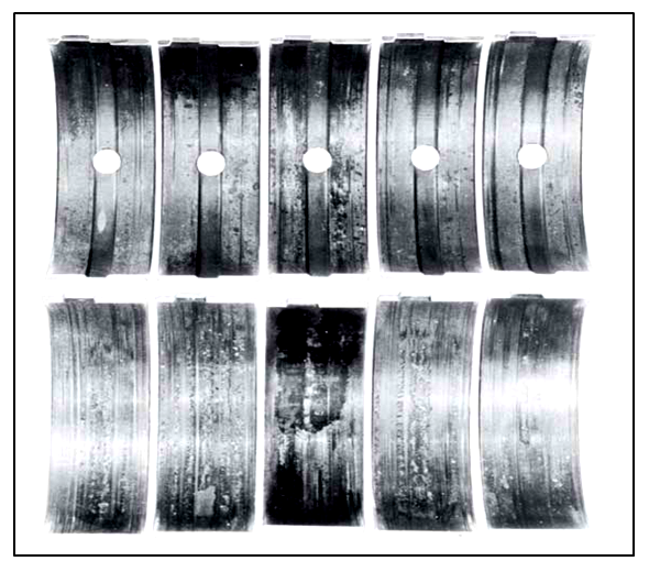 | Figure 3. Various conditions of damage to the crankpin bearing |
4. Conclusions
- 1. The engine power output, Ne, is 1,912 kW. Base on the maximum load 130% of normal, then the maximum engine power, Ne.max, 2 486 kW.2. The estimated magnitude of the indicated power, Ni, 2 825 kW, the indicated pressure, Pi, 307 N/cm2, and the thrust received by the piston, Fgh, 552 640 N.3. The maximum inertia forcé, received by the connecting rod bearing occurs at 0° and 360° crank angle, Fj, 62 316 N, and the total force received by the bearing, Fcr, 616 780 N.4. The average field pressure on the bearings, kmax, 162.5 kg/cm2, still below the standard tolerance whose value is 90-120 kg/cm2 for low speed diesel.5. The working condition characteristic, λcr, 58.15
 it is still below the standard of tolerance, that is 100-200
  .6. Low Pressure The indicator from the measurement, 18.5 kg/cm2 indicates that there is a problem with the piston ring, so that compression cannot be maximized.7. Damage that occurs to the bearing of the connecting rod is caused by carbon as a result of incomplete combustion that enters through the gaps in the piston ring. The results of the calculation of the load received by the crankpin bearing, wear is not caused by the force received, because everything is still within tolerance limits, but because of the presence of carbon powder due to incomplete combustion that enters through the piston ring gap and enters the lubricating crankcase and is mixed with lubricating oil and then enters between the crankshafts.