-
Paper Information
- Paper Submission
-
Journal Information
- About This Journal
- Editorial Board
- Current Issue
- Archive
- Author Guidelines
- Contact Us
Journal of Mechanical Engineering and Automation
p-ISSN: 2163-2405 e-ISSN: 2163-2413
2021; 10(1): 12-18
doi:10.5923/j.jmea.20211001.02
Received: May 3, 2021; Accepted: May 12, 2021; Published: May 26, 2021

Iterative Technique for Solving the Inverse Kinematics Problem of Serial Manipulator
 Abstract
 Reference
 Full-Text PDF
 Full-text HTML
Abdelrady Okasha Elnady
Mechatronics Department, Faculty of Engineering, O6University, Egypt
Correspondence to: Abdelrady Okasha Elnady, Mechatronics Department, Faculty of Engineering, O6University, Egypt.
| Email: |  |
Copyright © 2021 The Author(s). Published by Scientific & Academic Publishing.
This work is licensed under the Creative Commons Attribution International License (CC BY).
http://creativecommons.org/licenses/by/4.0/

The inverse Kinematics problem and obtaining its solution is one of the most important problems in robotics. It is quite complex, due to its non-linear formulations and having multiple solutions. It is not possible to formulate the solution of inverse kinematics problem in closed form, for all kind of robot configuration or for robots with high degrees of freedom. In the present work, an iterative technique to the IK problem solution of the serial manipulator is proposed. Iterative formulae for IK of 2-link and 3-link planar manipulators are presented. Joint variables for 2-link and 3-link manipulators are calculated using the present technique and compared with the exact one. The relative error is calculated for different iteration numbers. The results prove that the proposed algorithm is simple and efficient. The present technique can be applied to the serial manipulator with high degrees of freedom.
Keywords: Inverse Kinematics, Serial manipulator, Iterative Techniques
Cite this paper: Abdelrady Okasha Elnady, Iterative Technique for Solving the Inverse Kinematics Problem of Serial Manipulator, Journal of Mechanical Engineering and Automation, Vol. 10 No. 1, 2021, pp. 12-18. doi: 10.5923/j.jmea.20211001.02.
Article Outline
1. Introduction
- Kinematic problem solution is the first step for controlling the robot to carry out the desired task. Robotic manipulators are of many types; here only open chain serial manipulator is considered. Firstly, forward kinematics is evaluated, which can be easily analyzed using the Denavit-Hartenberg parameter. Next step is to evaluate inverse kinematics for obtaining joint variable for the defined pose of the robot. Closed form or analytical solution is the simplest one for inverse kinematics. But, it is not possible to obtain the analytical relation between joint variables and robot end effector position and orientation for all robot configurations, especially in case of high degrees of freedom manipulator due to its non-linear behavior. So, it is required to solve the inverse kinematics problem using another method.There are several techniques for solving IK problems. These include; cyclic coordinate descent methods [1], quasi-Newton and conjugate gradient methods [1,2,3], and neural net and artificial intelligence methods. Utilization of Neural network (NN) and Fuzzy logic to solve the inverse kinematics problems is much reported in [4-9]. Li-Xin Wei et al. [10] and Rasit Koker et al. [11] proposed neural network based inverse kinematics solution of a robotic manipulator.The cyclic coordinate descent method (CCD) is so popular because it is fast computationally, simple algorithmically, and straight-forward technique for generating IK solutions that can run at interactive frame rates.S R Buss [12] presented various Jacobian based methods demonstrating Pseudoinverse method being computationally fast but quality of approximation is poor. Pseudoinverse method gives very great end effector velocity near the singularity and also when the target is out of work space. M. R. de Gier [13] used Jacobian Pseudoinverse method for controlling robot having 6 DOF for application of 3D printing. It is noticed that, complexity in getting closed form solution increase with increase in DOF. In Jacobian Pseudoinverse method, the position is obtained by integrating the velocity as a result there would be a small drift in the solution, which can be reduced by reducing step size.Jacobian transpose method is the simplest one because it utilizes Jacobian transpose instead of Jacobian inverse. This reduces the computation of matrix inversion. The main advantage of this method is faster convergence, minimum computation, and less complexity. The Jacobian inverse method requires large computation for matrix inversion but it has fast convergence property [13]. This method is not very popular due to limitation as stated before. It has another limitation during singularity, when Jacobian loss its full-rank and Jacobian inversion becomes impossible or gives large velocity near to singular configuration. Jacobian matrix is of size (6 x n), where n is the number of degree of freedom. So, when the degree of freedom is less than 6 the Jacobian matrix becomes rectangular or not of full rank. As a result, calculation of Jacobian inverse becomes impossible. So, Moore Penrose inversion is the best possible approximate solution also known as pseudo inversion. The major common problem in the previous methods is a poor performance during singularity, which can be efficiently handled by Damped Least Square (DLS) method, by introducing a damping factor [14]. The damping factor damps the large velocity near singularity which makes the system robust against singularity. Also, the poor performance during singularity can be avoided by using a numerically stable technique for approximation. Ignacy Dule et al. [15], had made a comparative study for various Jacobian based methods i.e. Jacobian transpose, Jacobian pseudo-inverse, Damped least square method (DLS), Modified Damped least square method and approximation methods. The comparison is done on the basis of a number of elementary operations to compute iteration. It is shown that Pseudoinverse requires large operation followed by damped least square method and followed by Jacobian transpose method. This method is computationally cheapest and damped least square method is more better with bit more computational cost. Similarly, in comparison based on time consumed for computation, Pseudoinverse takes maximum computation time followed by DLS and Jacobian transpose method for movement of the end effector on a specific path. Dereli et al. [16] used two variants of particle swarm optimization (PSO) to calculate the inverse kinematics of a new 7-revolute jointed robot arm. The results obtained with Random Inertia Weight and Global Local Best Inertia Weight, are compared with the standard PSO. The PSO variables are much more effective than the standard PSO.Dereli et al. [17], proposed a quantum behaved particle swarm algorithm for inverse kinematic solution of a 7-degree-of-freedom serial manipulator and the results have been compared with other swarm techniques such as firefly algorithm (FA), particle swarm optimization (PSO) and artificial bee colony (ABC). The Quantum behaved PSO has yielded results that are much more efficient than standard PSO, ABC and FA. The advantages of the improved algorithm are the short computation time, fewer iterations and the number of particles.In the present work, an algorithm to the IK problem solution of the serial manipulator is proposed. Iterative formulae for IK of 2-link and 3-link planar manipulators are presented. Joint variables for 2-link and 3-link manipulators are calculated using the present technique and compared with the exact one. The relative error is calculated for different iteration numbers. The results prove that the proposed algorithm is simple and efficient. The present technique can be applied to the serial manipulator with high degrees of freedom.
2. Forward Kinematics (FK)
2.1. FK of 2-link Planar Manipulator
- The forward kinematics of 2-link planar manipulator can be obtained directly from geometry Fig. 1. The position coordinates (x, y) of the end effector is given in equations (1) and (2).
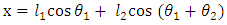 | (1) |
 | (2) |
 | Figure 1. 2-link planar manipulator |
2.2. FK of 3-link Planar Manipulator
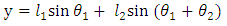
- The forward kinematics of 3-link planar manipulator can be obtained directly from geometry Fig. 2. The position coordinates (x, y) of the end effector is given in equations (3) and (4). The orientation of the end effector is given by equation (5)
 | (3) |
 | (4) |
 | (5) |
 | Figure 2. 3-link planar manipulator |
3. Inverse Kinematics
3.1. IK of 2-link Planar Manipulator
- The iteration formula for joint variables of the 2-link planar manipulator can be written in terms of the position coordinates (x, y) of the end effector as:
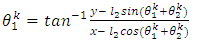 | (6) |
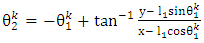 | (7) |
3.2. IK of 3-link Planar Manipulator
- The iteration formula for joint variables of the 3-link planar manipulator can be written in terms of the position coordinates (x, y) of the end effector as:
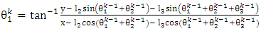 | (8) |
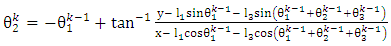 | (9) |
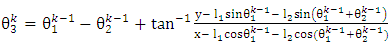 | (10) |
 is given by eq. (11).
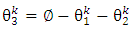 | (11) |
4. Results and Discussion
4.1. 2-link Planar Manipulator
- The iteration formulae for joint variables of 2-link planar manipulator given in equations (6) and (7) are applied to obtain the inverse kinematics of 2- link planar manipulator. Given an initial value to joint variable θ1, the joint variable θ2 is calculated. Using the obtained θ2 to calculate θ1 and repeat until certain acceptable error. The configuration of 2-link planar manipulator with
 and
and  are shown in Fig. 3. The coordinates are x = 6 and y = 4. The absolute error in x and y coordinates, is specified to be less than 10-3. The initial vlue of θ1 is zero.
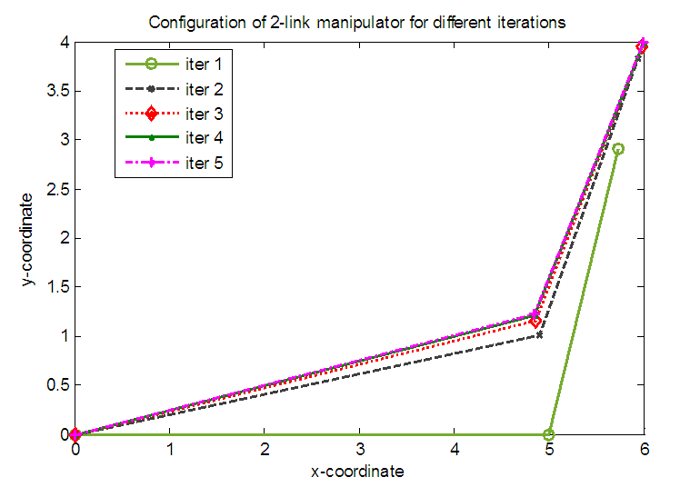 | Figure 3. Configurations of 2-link planar manipulator for different iterations |
|
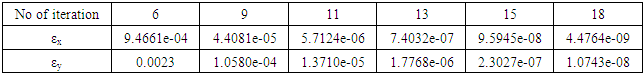
 | Figure 4. Variation of error in x and y coordinates with the number of iterations for 2-link planar manipulator |
|
|
 | Figure 5. Effect of initial value on the 2-link manipulator configuration |
4.2. 3-link Planar Manipulator
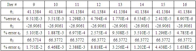
- The iteration formulae for joint variables of 3-link planar manipulator given in equations (8), (9) and (10) are applied to obtain the inverse kinematics of 3- link planar manipulator. Given an initial value to joint variable θ1 and θ2, the joint variable θ3 is calculated. Using the obtained θ3 to calculate θ1 and θ2, then repeat until certain acceptable error. The configuration of 3-link planar manipulator with
 ,
,  and
and  are shown in Fig. 6. The coordinates are x = 7, and y = 6. The absolute error in x and y coordinates, is specified to be less than 10-6. The initial vlue of θ1 is zero.
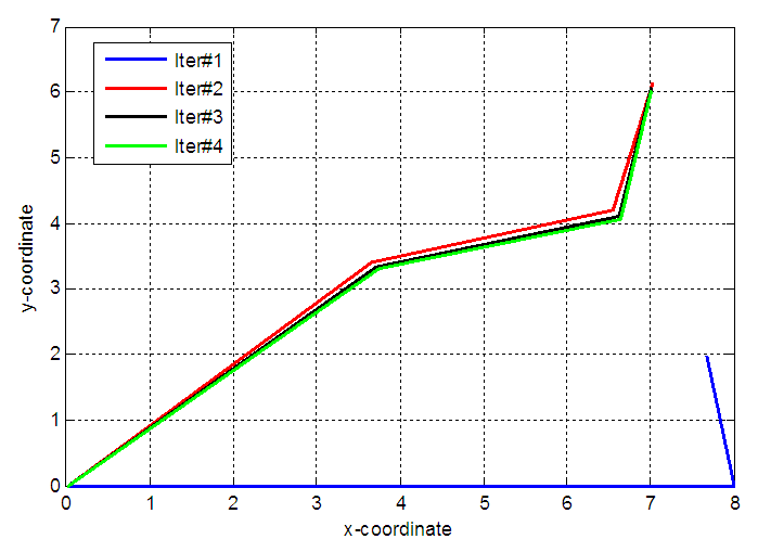 | Figure 6. Configurations of 3-link planar manipulator for different iterations |
|
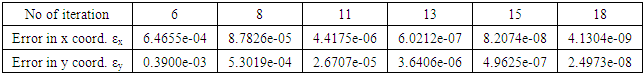
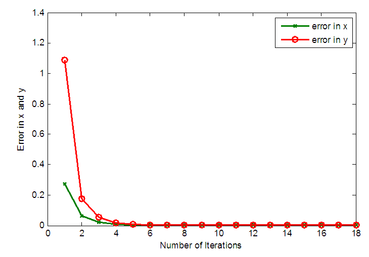
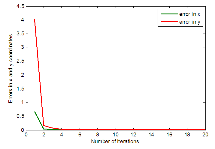 | Figure 7. Variation of error in x and y coordinates with the number of iterations for 3-link planar manipulator |
|
|
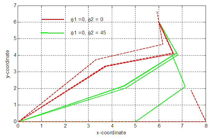 | Figure 8. Effect of initial values of θ1 and θ2 on the 3-link manipulator configurations |
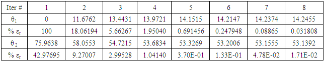
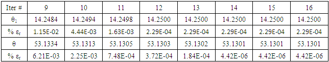
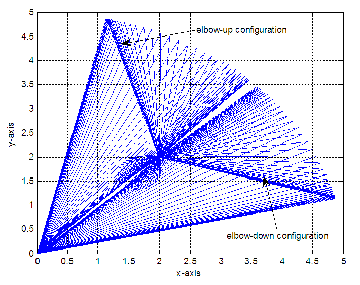
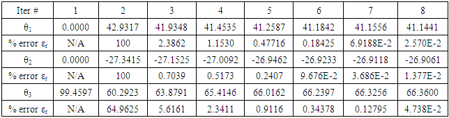
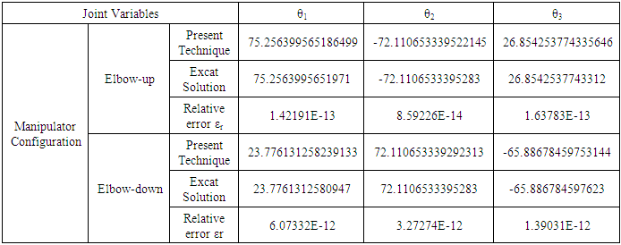
 is 30°. The joint variables θ1, θ2 and θ3 are obtained using the present technique with error adapted to be less than or equal 10-12 and compared with the exact one. The number of required iterations is 18. It is clear that the present technique is highly convergent and power full tool to find the inverse kinematics parameters of 3-link planar manipulator.The initial value of θ1 is 90° and θ2 is 0° for elbow-down configuration. The initial value of θ1 is 0° and θ2 is 0° for elbow-up configuration as shown in Fig. 9.
|
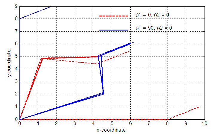 | Figure 9. Effect of initial values of θ1 and θ2 on the 3-link manipulator configurations |
5. Conclusions
- The mapping from the Cartesian space to the joint space is done by the iteration technique. An iteration algorithm to the IK problem solution of the serial manipulator is proposed. The iteration formulae for the IK of 2-link and 3-link planar manipulator are presented. The benefit of this method is that it is very simple and it can be used with any other serial robotic arm. Joint variables for 2-link and 3-link manipulators are calculated using the present technique and compared with the exact one. The relative error is calculated for different iteration numbers. Results show that the method is highly convergent and stable. Its convergence rate is exponentially as shown in the figures. The advantage of the method is that it easily tractable close to the singular configurations of the manipulator. Results of the application of the method on 2-link and 3-link manipulators are shown and clearly show that the technique is simple and accurate.