Mauton Gbededo1, 2, Chukwuemeke Onyenefa2, Matthew Arowolo1
1Department of Mechatronics Engineering, Federal University, Oye-Ekiti, Nigeria
2Department of Mechanical & Biomedical Engineering, Bells University of Technology, Ota, Nigeria
Correspondence to: Mauton Gbededo, Department of Mechatronics Engineering, Federal University, Oye-Ekiti, Nigeria.
| Email: |  |
Copyright © 2020 The Author(s). Published by Scientific & Academic Publishing.
This work is licensed under the Creative Commons Attribution International License (CC BY).
http://creativecommons.org/licenses/by/4.0/

Abstract
An epicyclic gear train consists of two gears, mounted so that the center of one gear revolved around the center of the other. A carrier connects the centers of the two gears and it rotates to carry one gear, called the planet gear or planet pinion, around the other, called the sun gear or sun wheel. The planet and sun gears were meshed so that their pitch circles rolled without slipping. A point on the pitch circle of the planet gear traced an epicycloid curve. This paper deals with analysis and verification of dynamic characteristics of an epicyclic gear train using the gear train and torque apparatus. The apparatus was installed in the Engineering lab while taking adequate safety precautions to ensure accurate collection of data. A record of the input, holding and output at various speed of the gear system were taken. At the end of the experiment, gear ratio, speed ratio and torque relationship of the epicyclic gear train were obtained. The experimental results were compared to the analytical data from various calculations using respective governing equations. It was observed that the experimental results were similar to the analytical data obtained for the speed ratio and torque relationship with a maximum 1.11% deviation between the two methods for torque relationship and 1.6% for the speed ratios, which were due to some frictional and mechanical losses in the belt and gear system. This paper provided further evidence that a gear train and torque apparatus is capable of determining and verifying the dynamic characteristics of the epicyclic gear rain.
Keywords:
Epicyclic gear train, Speed ratio, Torque relationship, Dynamic characteristics, Gear train and torque apparatus
Cite this paper: Mauton Gbededo, Chukwuemeke Onyenefa, Matthew Arowolo, Verification of the Dynamic Characteristics of an Epicyclic Gear Train Using Epicyclic Gear Train and Torque Apparatus, Journal of Mechanical Engineering and Automation, Vol. 9 No. 1, 2020, pp. 1-8. doi: 10.5923/j.jmea.20200901.01.
1. Introduction
A gear train is a mechanism with two or more gears meshed in series and its axes interlocked by a proper link to transmit power and to increase or decrease rotary speed [1]. The combinations of gear wheels used to increase or decrease speed of driven shaft is known as gear system. The prime movers like steam or gas turbines run at very high speed. The speed of turbine output is required to be reduced considerably by means of gear train; such gear train is known as reduction gear train. There are mainly four types of gear train: Simple gear train, Compound gear train, Reverted gear train, Planetary or Epicyclic gear train [2].Epicyclic gearing arrangements consists of four different elements that produce a wide range of speed ratios in a compact layout. These elements are: (i) Sun gear, an externally toothed ring gear co-axial with the gear train; (ii) Annulus, an internally toothed ring gear co-axial with the gear train; (ii) Planets, externally toothed gears which mesh with the sun and annulus; and (iv) Planet Carrier, a support structure for the planets, co-axial with the train. The name "epicyclic" is derived from the curve traced by a point on the circumference of a circle as it rolls on the circumference of a second fixed circle. By fixing one of the co-axial members and using the remaining two for input and output, three types of simple single-stage epicyclic gearing are possible. Generally, these are called planetary, star, and solar arrangements. This study is primarily concerned with planetary gear drives shown in Figure 1, which have a fixed annulus with the planet carrier rotating in the same direction as the sun gear. 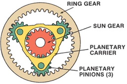 | Figure 1. The Epicyclic Gear Train |
For a planetary arrangement with three planets, each tooth engagement of the sun gear would have to carry one third of the total load. Consequently, the dimensions of the sun gear would be one-third of the pinion of a parallel shaft gear train designed to transmit an equivalent torque. It should be pointed out that six planets do not necessarily give a gearing twice the capacity of a similar one having only three planets. It is impossible to guarantee equal loading among more than three planets due to quality and accuracy of workmanship. For this reason, three planet designs are preferred, although systems with up to eight planets are commercially available [3].Epicyclic Gear Train (EGT) has a number of advantages over parallel shaft gear trains. Because of their compactness and relatively low weight-to-speed reduction ratios, they are widely used in aerospace and automotive applications. EGT has particular features, such as load sharing by several gear pairs, simultaneous internal and external gear meshing, and plane motion of the elements. Because of these features, the dynamic behaviour of EGT is so complicated that numerous investigations have been executed on analytical and experimental study [4].Epicyclic gear systems have a long history of industrial use. James Watt in 1781 patented a sun and planet gear arrangement used in one of his early engines. However, advances in internal gear manufacturing did not parallel those in external gears, limiting the development of epicyclic gear trains. As industrial applications required transmissions with higher power ratings, the performance of epicyclic gear systems became poorer at higher loads since load equalization among the planet gears was not realized due to poor manufacturing and assembly techniques. Very few studies have been reported on the dynamic behaviour of the Epicyclic Gear Train (EGT) with journal bearings [5].The main objectives of this study are:1) Determine and verify the gear ratio of Epicyclic gear train.2) Measure and verify the speed ratio of Epicyclic gear train.3) Analyze and verify the Torque relationship of Epicyclic gear train.
2. Literature Review
Since the Epicyclic gear train (EGT) is an assembly of both external and internal spur gears, this literature review relies on information for EGT's as well as its individual components in showing the progress and current status of epicyclic gearing. Investigation into the action of the separate elements must be made in order to better understand the behavior of the entire system. Consequently, information is presented chronologically, and in separate sections, for external/internal spur gears and EGT's, respectively.
2.1. The Spur Gear
A major factor in the design of spur gear in mesh, as shown in Figure 2 is the power that must be transmitted from the prime mover to the load. The force that is transmitted becomes important in designing for gear tooth beam strength, contact stress and scoring factor. Dynamic effects must be considered since the load is being transmitted by an elastic medium, i.e., deflected gear teeth. Consequently, the instantaneous load to which the engaged gear teeth are subjected is generally higher than the nominal statically calculated load.is generally higher than the nominal statically calculated load [6].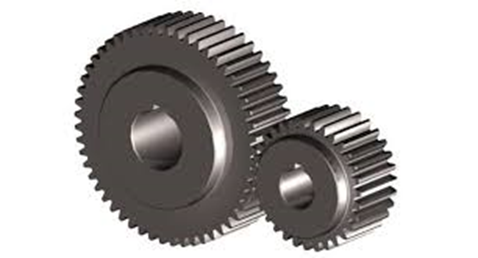 | Figure 2. Spur Gears in mesh |
2.2. Epicyclic Gear
Epicyclic gears have been used as early as the 1700's. However, the first recorded attempt to apply engineering analysis was made in the very late 1800's [7].
2.2.1. Mathematically Analysis of the Dynamic Characteristic of Epicyclic Gear Train
A simple Epicyclic gear train is shown in Figure 3, where a gear A and the arm C have a common axis at O1 about which they can rotate. The gear B meshes with gear A and has its axis on the arm at O2, about which the gear B can rotate. If the arm is fixed, the gear train is simple and gear A can drive gear B or vice- versa, but if gear A is fixed and the arm is rotated about the axis of gear A (i.e. O1), then the gear B is forced to rotate upon and around gear A. Such a motion is called epicyclic and the gear trains arranged in such a manner that one or more of their members move upon and around another member are known as epicyclic gear trains (epi. means upon and cyclic means around). The epicyclic gear trains may be simple or compound [8].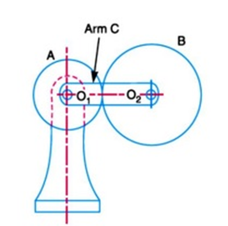 | Figure 3. Schematic diagram of Epicyclic Gear Train |
The three most important dynamic characteristics of the Epicyclic Gear Train analysed using mathematical methods are;• Gear Ratio• Velocity Ratio • Torque Ratioa. Gear Ration dynamics characteristicsThe gear ratio of an epicyclic gearing system is somewhat non-intuitive, particularly because there are several ways in which an input rotation can be converted into an output rotation. The overall gear ratio of a simple planetary gear set can be calculated using the following equations, [9], representing the sun-planet and planet-ring interactions respectively.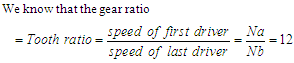 | (1) |
Also, | (2) |
Na = Nb being on the same shaftFor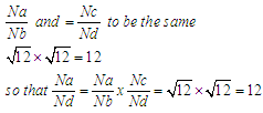 | (3) |
b. Speed ratio characteristicsIn this method, the motion of each element of the epicyclic in relative to the arm is set down in the form of equations. The number of equations depends upon the number of elements in the gear train. However, the two conditions are, usually supplied in any epicyclic train viz. some element is fixed and the other has specified motion. These two conditions are sufficient to solve all the equations; and hence to determine the motion of any element in the epicyclic gear train. Let the arm C be fixed in an epicyclic gear train as shown in Fig. 3. Therefore, speed of the gear A relative to the arm C is;  | (4) |
and speed of the gear B relative to the arm C,  | (5) |
Since the gears A and B are meshing directly, therefore they will revolve in opposite directions.  | (6) |
c. Torque ratio characteristics In epicyclic gears, two speeds must be known, in order to determine the third speed. However, in a steady state condition, only one torque must be known, in order to determine the other two torques. When the rotating parts of an epicyclic gear train, as shown in Figure 4, have no angular acceleration, the gear train is kept in equilibrium by the three externally applied torques, viz:• Input torque on the driving member (T1),• Output torque or resisting or load torque on the driven member (T2),• Holding or braking torque on the fixed member (T3).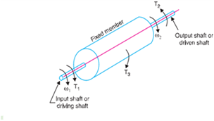 | Figure 4. Torques in epicyclic gear train |
The net torque applied to the gear train must be zero. In other words;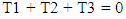 | (7) |
Therefore,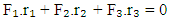 | (8) |
where,F1, F2 and F3 are the corresponding externally applied forces at radii r1, r2 and r3.Furthermore, if ω1, ω2 and ω3 are the angular speeds of the driving, driven and fixed members respectively, and the friction be neglected, then the net kinetic energy dissipated by the gear train must be zero, i.e. | (9) |
But, for a fixed member,  | (10) |
Therefore, | (11) |
Note that, (a) from equations (9) and (11), the holding or braking torque T3 may be obtained as follows 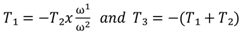 | (12) |
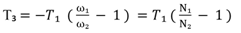 | (13) |
(b) when input shaft (or driving shaft) and output shaft (or driven shaft) rotate in the same direction, then the input and output torques will be in opposite directions. Similarly, when the input and output shafts rotate in opposite directions, then the input and output torques will be in the same direction.
2.3. Investigation of Previous Work on Dynamics Behaviours of the Epicyclic Gear Train
Research in the field of evaluating the results of dynamics characteristics of the epicyclic gear train has increased dramatically over the past two decades. The wide range of research topics demonstrated the technical challenges of understanding and predicting epicyclic gear dynamics behaviour. The research in this review includes mathematical models, vibration mode properties, dynamic response predictions including nonlinearities and time-varying mesh stiffness fluctuations, the effects of elastic compliance, and gyroscopic effects, among other topics. Practical aspects are also included, for example, planet load sharing, planet phasing, tooth surface modifications, and characteristics of measured vibration response.Tuplin [10] used an equivalent spring-mass system representing the gears in mesh to determine the dynamic loads in gear teeth. The spring stiffness was determined from the static load deflection of two contacting teeth, which was considered constant and linear. It was observed that dynamic load characteristics of the gear train occurred from the passage of "thick" teeth through the meshing zone. The graph in Figure 5 shows the result of power flow analysis based on the position of each planet gear through one revolution in the fixed ring gear model. In the fixed ring gear model, when the carrier rotated 0° and 240°, the load sharing characteristics was smallest. When the carrier rotated 0°, the power of planet gear 1 was 3.805 kW, the power of planet gear 2 was 3.279 kW and the power of planet gear 3 was 3.612 kW, so that Ky was calculated to be 1.053. When the carrier rotated 240°, the power of planet gear 1 was 3.805 kW, the power of planet gear 2 was 3.752 kW, and the power of planet gear 3 was 3.279 kW. The maximum power was 3.805 kW for planet gear 1, and the average power was 3.612 Kw, so that Ky was calculated to be 1.053.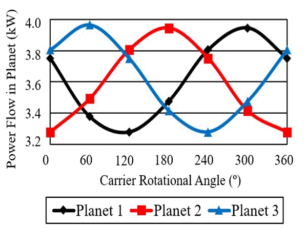 | Figure 5. Load sharing characteristics of the spur gear and the ring gear |
Bollinger [11], was one of the first to consider the application of a Fixed-Variable Gear Mesh Stiffness model (FVMS) for the analytical determination of the tooth stiffness as a periodic function. However, discontinuities in the effective stiffness between gear pairs resulted from the change from single to double tooth contact and the change back from double to single tooth contact.Liu [12], developed a valid and generalized dynamic model based on the bond graph theory for planetary gear set. In this regard, free torsional vibration analysis of a planetary gear set is carried out to demonstrate the application of the bond graph model in mode analysis. The results indicated that the model could not only predict the natural frequencies and the displacement mode shapes, but also obtain the generalized deformation mode shapes simultaneously.Nikolajsen et al. [13], obtained the transient loci of the planetary gears supported with journal bearings assuming the gear mesh forces are independent on the bearing position and reaction. They ignored the fact that the behaviour of the gear and bearing characteristics are coupled to each other.Bahgat et al. [14], studied the effect of bearing clearances on the dynamic tooth load and bearing forces for a planetary spur gear with a fixed ring gear. In their study, bearing forces and clearance angles were obtained without applying hydrodynamic lubrication theory.Presently, planetary gears are frequently used as main reduction gears in propulsion gas turbines for merchant ships. They are widely used in rotor drive gearboxes for helicopter aircraft. In lower horsepower applications, high ratio planetary systems are combined with hydrostatic drives to produce wheel drives for agricultural and off-highway equipment.Xiao [15], applied finite element method to investigate the non-linear dynamic characteristics of a coated gear transmission system, which significantly improved the load-carrying performance of a gear surface. The non-linear factors such as variable mesh stiffness, friction, backlash, and transmission error, a six-degree-of-freedom spur gear transmission system with coatings were presented. Poincare map, and fast Fourier transform spectrum, the dynamic characteristics and the effects of the coating elastic modulus on vibration behaviours of a gear transmission system were minutely dissected by using a numerical integration approach.The moment of force (MR force) Fy has a significant impact on the vibration transmissibility of the systems, as shown in Figure 6. It can be seen that as Fy increases, the vibration transmissibility decreases and the systems becomes more stable. As Fy makes little contribution to the systems equation, the resonance frequency changes inconspicuously.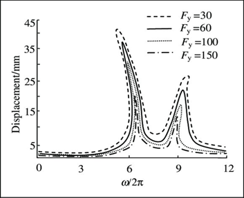 | Figure 6. The effect of Fy on the vibration transmissibility |
3. Experimentation
The diagram in Fig. 7 is the Gear train and torque apparatus installed in the Engineering lab to carry out the experiments used to obtain the gear ratio, speed ratio and torque relationship. The results obtained from the experiments were compared to analytical data obtained by calculations.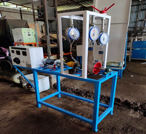 | Figure 7. Epicyclic Gear Train and Torque Apparatus |
In case of Epicyclic Gear-Train, the axis of the shaft on which the gear were mounted move relative to a fixed axis. In this apparatus, Internal Type (Experimentation Model) Epicyclic Gear train was demonstrated. It consists of SUN gear mounted on the input shaft. Two-planet gear are on the both side meshes with SUN gear and which meshes with the internal teeth of the annual gear. Two-planet gear are mounted on the pins, which are fitted into both ends of the arms. Output shaft is connected to the arm on which drum is fixed.
3.1. Specification of Gear Train and Torque Apparatus
The following of the specification of the experimental apparatus;1. Epicyclic Gear train. Ratio = 1:8.2. Belt / rope and spring balance arrangement to measure output torque and holding torque.3. Radius of output drum, R= 80 mm.4. Radius of holding drum, r= 65 mm.5. 1 H.P. D.C. shunt motor, 1500 rpm, 230 v, 4Amp.6. Control panel with dimmer (DC) for speed variation and Ammeter and Voltmeter to input power, RPM Indicator.7. Internal Epicyclic Gears made of;(i) Ring gear having 70 teeth,(ii) sun gear having 10 teeth, and;(iii) planet gear having 30 teeth.
3.2. Experimental Procedures
The following procedures were taken during the experiment1. The apparatus was set up according to the detailed description in the manual as displayed in Fig. 7.2. Power supply was given to the motor from the control panel.3. The moor was put on (by properly connecting the control panel) and slowly increase the speed to 200 rpm and the corresponding output shaft speed was observed. The two such speeds were taken and the speed ratio were evaluated and verified with corresponding analytical method.4. The holding torque was applied just to hold the braking drum. This was done carefully.5. The corresponding spring balance reading were taken at the braking drum.6. Loads were applied to the output shaft until the spring at braking drum location becomes exactly vertical and at full tension. This was done carefully.7. For the experiment, the motor speed was increased increased the motor speed from 200rpm to 1000rpm and five corresponding spring balance readings were at output drum and holding drum.8. The corresponding input torque, holding torque and output torque were evaluated.9. The results of the torque of the input, holding and output drum were compared to data form analytical methods to verify the torque relationship.We know that,Ti + Th + To = 0Ti = Input TorqueTh = Holding TorqueTo = Output Torque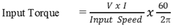 | (9) |
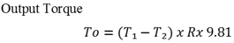 | (10) |
Where, T1 - T2 = readings of the tensions in the spring balance at the output drum.Holding torque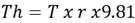 | (11) |
Therefore,  | (12) |
 | (13) |
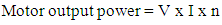
where,V = Motor input voltage I = Motor input current | (14) |
10. All records of observation were tabulated and these results were compared to the analytical methods obtained from corresponding governing equations to verify the dynamics characteristics of the epicyclic gear train.
4. Results and Discussion
The results of the experimental method and the analytical methods were obtained and compared to verify the dynamic characteristics of the epicyclic gear train.
4.1. Results of Experimental Speed Ratio
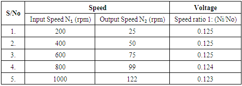
The input speed were varied between 200rpm to 1000rpm and corresponding output speed were tabulated.Table 1. Results of the Experimental speed ratios
 |
| |
|
The result obtained from Table 1 shows that the Speed ratio was constant at 0.125 from 200 rpm to 600 rpm but decreases insignigantly to 0.124 and was minimum at 1000 rpm with 0.123 constant.
4.2. Results of Analytical Speed Ratio
We know that,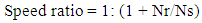 | (15) |
Where, Nr = Number of teeth of the ring gear Ns = number teeth of the sun gearGiven; Nr = 70 teeth Ns = 10 teethTherefore, | (16) |
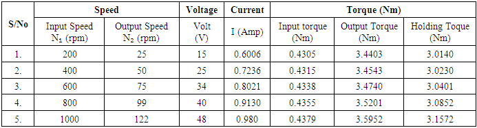
4.3. Results of Experimental Torque Calculations
The values of the experimented input torque Ti, Output torque To and Holding torque Th, were also tabled as shown in Table 2 below.Table 2. Results of Experimented Torque calculations
 |
| |
|
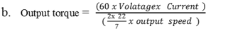
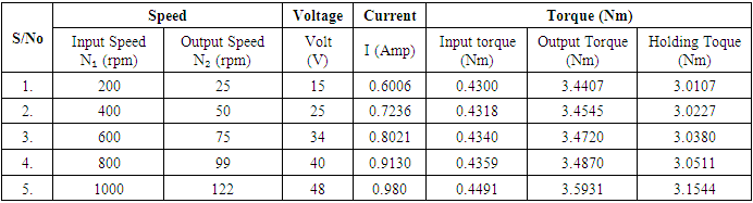
4.4. Results of Analytical Torque Analysis
The following governing equations were used to evaluate the various values of the input, output and holding torques respectively.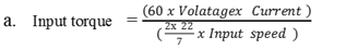 | (17) |
 | (18) |
 | (19) |
(i) When Ni = 200rpm and N₂ = 25 Ti = 0.4300, To = 3.4407 and Th = 3.0107(ii) When Ni = 400rpm and N₂ = 50 Ti = 0.4318, To = 3.4545 and Th = 3.0227(iii) When Ni = 600rpm and N₂ =75 Ti = 0.4300, To = 3.4407 and Th = 3.0107(iv) When Ni = 800rpm and N₂ = 100 Ti = 0.4359, To = 3.4870 and Th = 3.0511(v) When Ni = 1000rpm and N₂ = 125 Ti = 0.4491, To = 3.5931 and Th = 3.144The results obtained for the analytical torque calculation are shown in Table 3 below.Table 3. Results of Analytical Torque calculations
 |
| |
|
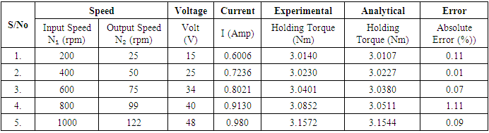
4.5. Discussion
In order to verify the dynamic characteristics of the epicyclic gear train, the two method of evaluations: experimental and analytical methods were compared. The speed ratio for the Experimental methods various between 0.123 to 0.125  | (20) |
Comparison of analytical and experimental results for torque shows error of 0.01% to 1.11%. It means that efficiency of experimental set up that we have used is not 100%. The deviations were caused by frictional losses and mechanical losses in the gear system. It was also observed that various parameters affect the torque results like motor efficiency, frictional losses between belt and rope drum, spring stiffness as well as spring stiffness from the spring balance during measurement. Comparison between the two torques is shown in Table 4 below.Table 4. Comparison between experimental torque and analytical torque
 |
| |
|
5. Conclusions
This study evaluated the holding or braking torque in epicyclic gear train both by experimental and analytical method. The three dynamic characteristics obtained and verified are the gear ratio, speed ratio and torques relationships. At the end of experimentation and analytical evaluation using appropriate governing equations, it was established that results obtained from both methods are the same with maximum deviation of 1.11% deviation for torque relationship and 1.6% for the speed ratios. These insignificant errors emanated from some frictional and mechanical losses in the belt and gear system. This work provided further evidence that a gear train and torque apparatus is capable of determining and verifying the dynamic characteristics of the epicyclic gear rain. This study would recommend another experimental verification of the dynamic characteristics of a compound gear train and the use Solid work or MATLAB to provide future method of verification for simple epicyclic gear train.
References
| [1] | Uicker. J.J., Pennock G.R., and Shigley, J.E (2019): Internal gear strains and load sharing in planetary transmissions – model and experiments, ASME Journal of Mechanical 130 (7), pp. 340-352. |
| [2] | Sutar S.S. (2016): Torque measurement in Epicyclic gear train, International Journal of Engineering and Advanced Technology 5(6) pp.185-188. |
| [3] | Wright, M. T. (2007): "The Antikythera Mechanism reconsidered", Interdisciplinary Science Reviews. 32 (1): pp.27-43. |
| [4] | Nikolajsen J. L, Botman M., (2012): Dynamic Behaviour of a Journal Bearing in a Planet Gear, ASLE Transactions, 26(1), pp. 87-93. |
| [5] | Freudenstem M. S. and Yang T. S (2014): Dynamic Behaviour of Planetary Gears, 3rd Report, Bulletin of the International Journal of the Japan Society of Mechanical Engineers (JSME), 19(138), pp. 1563-1570. |
| [6] | Ali M.S., Will A. W (2019): Mark Standard Handbook for Mechanical Engineers, 13(2) pp. 1023-1050. |
| [7] | Lanchester, F.W. and Lanchester, G.H: Epicyclic Gears", Proceedings of the Institute of Mechanical Engineers, 134(1) pp. 605, 1924. |
| [8] | Khurmi, R. S., and Gupta, J. K. (2012): Theory of machines New Delhi: S. Chand & Co. Ltd. pp. 774-832. |
| [9] | Ulrich K., Inho B., (2011): Optimization Procedure for Complete Planetary Gearboxes with Torque, Weight, Costs and Dimensional Restrictions, Applied Mechanics and Materials Vol. 86 pp 51- 54. |
| [10] | Tuplin, W.A., (2009): Dynamic Loads on Gear Teeth, Machine Design, p. 203, Oct. 1953. |
| [11] | Bollinger, J. G. (2020): Deformation of loaded gears and its effects on the load carrying capacity, Journal of Mechanical Vibration 46(961) pp. 450-462. |
| [12] | Liu, F.; Jiang, H.; Yu, X. (2011): Dynamic behaviour analysis of spur gears with constant & variable excitations considering sliding friction influence, Journal of Mechanical Science and Technology, 30, 5363–5370. |
| [13] | Nikolaisen M., Takahashi, T., and Masuko, M. (2010): Two Effects of Intermediate Rings on the Load Sharing of Epicyclic Gearing, Paper presented to the International Symposium pp.13-16. |
| [14] | Brahgat. H., Huang, K., Sang, M. (2012). Nonlinear dynamic modelling and analysis for a spur gear system with time-varying pressure angle and gear backlash, Mech. Syst. Signal Process. pp.132, 18–34. |
| [15] | Xion L., Zuo, M.J.; Feng, Z. (2018): Dynamic modeling of gearbox faults, Mech. Syst. Signal Process. pp.98, 852–876. |

 Abstract
 Reference
 Full-Text PDF
 Full-text HTML