-
Paper Information
- Paper Submission
-
Journal Information
- About This Journal
- Editorial Board
- Current Issue
- Archive
- Author Guidelines
- Contact Us
Journal of Mechanical Engineering and Automation
p-ISSN: 2163-2405 e-ISSN: 2163-2413
2018; 8(3): 78-83
doi:10.5923/j.jmea.20180803.02

Model Based Development Using Hardware in the Loop Simulation for Servo Press Machine
 Abstract
 Reference
 Full-Text PDF
 Full-text HTML
Tetsuaki Nagano1, Masaya Harakawa2, Koji Akiyama3, Masami Iwase4, Jun Ishikawa4, Hisao Koizumi5
1M-TEC COMPANY Ltd., Osaka, Japan
2Mitsubishi Electric Corp., Tokyo, Japan
3Itec Hankyu-Hanshin Co. Ltd., Tokyo, Japan
4Tokyo Denki University, Tokyo, Japan
5M2M Study Group, NPO Organization, Kanagawa, Japan
Correspondence to: Tetsuaki Nagano, M-TEC COMPANY Ltd., Osaka, Japan.
| Email: |  |
Copyright © 2018 The Author(s). Published by Scientific & Academic Publishing.
This work is licensed under the Creative Commons Attribution International License (CC BY).
http://creativecommons.org/licenses/by/4.0/

This paper presents a proposal of Model-Based Development (MBD) for efficient development of a control method of a large industrial machine such as a press machine using Hardware-In-the-Loop Simulation (HILS) verification system that can accommodate combined phenomena in mechanical, electrical, and control fields. The proposed HILS verification system consists of an actual servo amplifier, an actual controller, and a real-time simulator with machine model, motor models, and electric circuit models installed. It is possible to optimize the control method and parameters for various operating conditions. The proposed method was applied to the design and verification of a control method that suppresses fluctuations in the DC-link voltage and motor current during the press operation of a press machine driven by a 75 kW servo motor. Its effectiveness was confirmed.
Keywords: Hardware-in-the-loop, HIL, MBD, Model based development, Press machine, Servo
Cite this paper: Tetsuaki Nagano, Masaya Harakawa, Koji Akiyama, Masami Iwase, Jun Ishikawa, Hisao Koizumi, Model Based Development Using Hardware in the Loop Simulation for Servo Press Machine, Journal of Mechanical Engineering and Automation, Vol. 8 No. 3, 2018, pp. 78-83. doi: 10.5923/j.jmea.20180803.02.
Article Outline
1. Introduction
- In recent years, model-based-development (MBD) for develop-ment and verification of control systems has shown diffusion and expansion, mainly in the automotive field [1-6]. For automobiles, MBD is applied by design departments for bodies, engines, and electrical equipment systems cooperatively from the basic design stage.However, for industrial machines such as press machines, it is said that servo systems, which consist of controller, servo amplifiers and servo motors, are supplied as general-purpose products of factory automation (FA) equipment manufacturers. It is often true that the supply is done in the final stage of machine design or in the completion stage of a prototype machine. For these reasons, it is difficult for the industrial machinery field to apply MBD to the automotive field. Therefore, in the industrial machinery field, the development of a control method and parameter tuning of the servo amplifier is performed using an actual machine. At this stage, when difficulties related to electricity, machinery, and control occur, it often takes much time to ascertain the cause and to take measures.This paper presents a proposal of MBD using a Hard-ware-In-the-Loop Simulation (HILS) verification system, which can accommodate phenomena in the electrical, mechanical, and control fields and resolve difficulties described above, which are encountered during the development of a servo control system for industrial machine. The proposed HILS verification system consists of an actual servo amplifier, an actual controller, and a real-time simulator with a machine model, motor models, and electric circuit models installed. One can optimize the control method and parameters for various operating conditions. After the proposed method was applied to a press machine driven by a 75 kW servo motor, its effectiveness was confirmed.
2. Conventional Design Methods of Servo Control and Associated Problems
2.1. Press Machine Servo System Configuration
- Figure 1 presents the basic configuration of the servo system of a press machine, which is an industrial machine. This system comprises a controller, a servo amplifier, a servo motor, and an AC/DC converter. These control devices are general-purpose products made by FA equipment manufacturers. After a servo amplifier receives speed commands from a controller, it controls the servo motor speed and torque. The AC/DC converter converts AC voltage to DC voltage to supply power to the servo amplifier. It temporarily stores kinetic energy returned from the machine during regenerative operation of the servo motor in a capacitor.
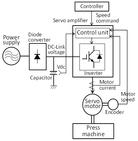 | Figure 1. Basic configuration of servo system of press machine |
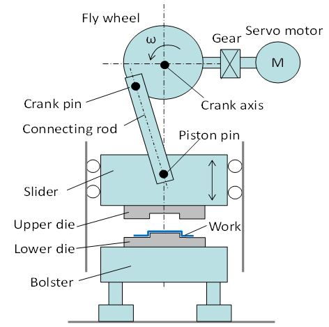 | Figure 2. Structure of crank press machine |
2.2. Design Verification of the Press Machine Servo System
- Figure 3 portrays the conventional design flow of the servo control. First, the FA equipment manufacturer selects the capacity of the servo amplifier, the motor, and the converter based on the mechanism, the basic machine specifications (length, mass, inertia moment), and the operation pattern of the prototype machine presented by the machine manufacturer. Next, the FA equipment manufacturer verifies the control method and adjusts its parameters by actual combination testing by the prototype machine and the servo system. This process involves various phenomena related to electrical, mechanical, and control fields such as mechanical vibration, torque saturation of a servo amplifier, and power regeneration. Large machines take time to prepare for the test. Moreover, the operation conditions might be restricted for safety reasons.
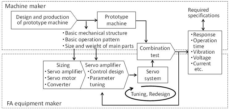 | Figure 3. Conventional design flow of servo control |
2.3. Design Verification of the Press Machine Servo System
- From the discussion presented above, the combination test of a press machine presents the following difficulties. 1) It is difficult for an FA equipment manufacturer to occupy a prototype machine and conduct experiments. 2) Because a press machine is large, it is restricted by the place and equipment of the experiment. It takes time to prepare the experiment. 3) When difficulties related to electricity, machinery, and control arise, it takes time to ascertain the cause and to take countermeasures. Therefore, efficient development is difficult when using a conventional verification method based on actual combination tests.
3. Proposed MBD Method Using HILS
3.1. System Configuration and Operation
- Figure 4 presents the configuration of a HILS test system as a solution to the difficulties described above. Hereinafter, system features are described. A real-time simulator is furnished by mathematical models of a power circuit consisting of a servo amplifier and a converter, a power supply, a servo motor, and a machine. Switching operation of the power circuit model is conducted using a PWM switching signal from control unit boards of the servo amplifier. Then a motor current is applied to the motor model. It generates motor torque that drives the machine. Electric signals equivalent to the output signal of an actual current detector and encoder are generated respectively for the motor current and motor angle. Then they are fed back to the control unit board. Thereby, the control unit board of the servo amplifier behaves equivalently to control of an actual power circuit and motor, respectively. A machine model can carry oscillation and other characteristics to simulate actual mechanics by the combination of masses, inertia elements, spring elements, etc. This system uses no actual machine, motor, or power circuit. For that reason, it requires a small footprint. Note that this real-time simulator is a newly developed high-performance model based on the model [7] developed previously by the authors.
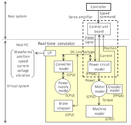 | Figure 4. Constitution of HILS verification system for drive system of industrial machine |
3.2. Electrical Model Preparation
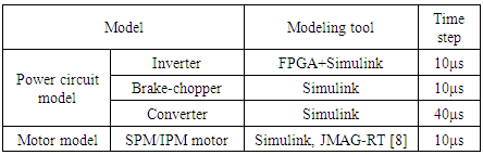
- Previously described electrical system models (1)–(5) simulate a servo system. The electrical engineers of an FA equipment manufacturer prepare those models and register them into an electrical system model library. The electrical library is generally registered in the database of the appliance manufacturer. Table 1 presents tools used for model preparation and the simulation time step. These electrical system models are installed to the real-time simulator by converting a Simulink model into an execution code.
|
3.3. Machine Model Preparation
- (a) This proposal assumes that the mechanical engineers of a FA equipment manufacturer prepare a representative machine model and register it to a machine model library. A control engineer configures machine constants such as length, mass, and a spring modulus to the model to establish a machine model that is applicable to a real machine. The multi-domain modeling tool SimulationX [9] is used for machine model preparation. Consequently, the FA equipment manufacturer engineers can prepare a different machine model efficiently for each machinery manufacturer.(b) Figure 5 portrays a procedure of the mechanical engineers of a FA equipment manufacturer to prepare the template model of a machine. First, a model of typical mechanisms of industrial machinery is prepared using multiple connections of standard machine elements of SimulationX on the block diagram editor. It is then registered in the mechanism model library. The mechanical engineers establish a library of machine models by a model not included in the library by combining mechanism models and standard elements, which reduces time substantially, rather than developing a newly machine model.(c) Because a Simulink model must be converted into an execution code to install a model to a real-time simulator, the machine model library on SimulationX is converted into a Simulink model using the SimulationX conversion function. A machine model corresponding to each machine is completed by inputting the length, mass, and inertia moment determined by mechanical specifications into the machine model on Simulink as parameters.(d) The HILS verification system in Figure 4 as a substitute for real system verification is completed by converting the main circuit, motor, and machine models selected from the model library on Simulink into execution codes and installing them in the real time simulator.
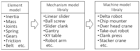 | Figure 5. Procedure of preparation the template model of a machine |
4. Results from Proposed Application
- This section describes application of the proposed method for development of a control method that suppresses fluctuations in the DC-link voltage during the press operation of a press machine driven by a 75 kW servo motor.
4.1. Machine Model of Crank Press
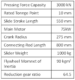
- Figure 6 presents a model of the crank press machine prepared by SimulationX based on the basic specifications of Table 2 presented by the machine manufacturer. In the model of Figure 6, the rated pressing force (3000 kN) is set as generated from 10 mm above the bottom dead center. This model is implemented in the machine model part in the real-time simulator presented in Figure 4.
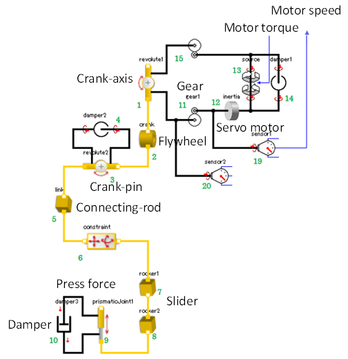 | Figure 6. SimulationX model of crank press machine |
|
4.2. Suppression Control for DC-link Voltage Fluctuation
- When the press operation starts, the motor speed decreases because of the pressing force as a disturbance. Because the servo motor is controlled to have constant speed, after some time, when the pressing force is lost, the motor speed once overshoots and then settles at the command value. At this time, the kinetic energy of the mechanical system including the motor is regenerated to the servo amplifier, whereby the DC-link voltage (capacitor voltage) rises. To prevent the press machine from being stopped because of the overvoltage error of the DC link voltage, conventionally, a brake chopper device that consumes electric power by resistance has been installed separately.We propose a control method that is able to suppress fluctuation of the DC link voltage without using the brake chopper device by compensating the torque command based on the DC link voltage shown in Figure 7. The proposed control method was implemented as the servo amplifier control program.
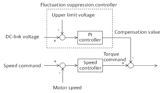 | Figure 7. Block diagram of proposed DC-Link voltage fluctuation suppression control method |
4.3. Experimental Work and Discussion
- Figures 8 and 9 respectively display the response waveforms of the HILS verification system and the actual combination test. The left side shows the waveform in the HILS verification. The right side shows the waveform in the actual combination test. The HILS waveforms were measured before the combination test. Figure 8 depicts the waveforms obtained when the proposed fluctuation suppression control is not used. The DC link voltage is suppressed below the upper limit voltage by the brake chopper device, but the variation in the motor current is large. Figure 9 portrays the waveform obtained when the proposed fluctuation suppression control is used instead of using a brake chopper. Although the brake chopper is not used, the DC link voltage is suppressed below the upper limit value. The fluctuation of the motor current is also small. Moreover, probably the waveforms of HILS and the actual machine test are generally mutually similar. The difference between them is apparently attributable to the error of the machine model, the pressing force model, and the omission of friction of the slider.
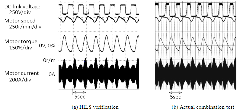 | Figure 8. Experimental results conventional DC-Link voltage fluctuation suppression control with brake chopper |
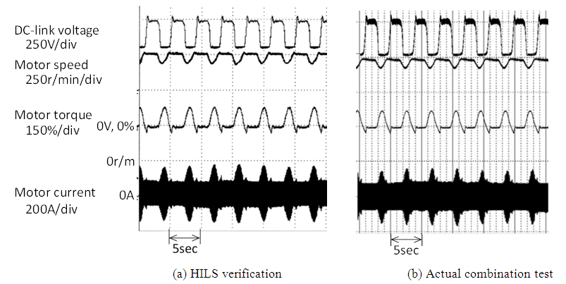 | Figure 9. Experimental results with proposed DC-Link voltage fluctuation suppression control (without brake chopper) |
5. Conclusions
- The proposed method, constituted as described above, enables verification of the control system even for large machinery using a high-voltage, large-capacity motor without using actual power circuits, motors, and machines. Therefore, even a software engineer and a control engineer can accommodate it easily. No restriction in the power source environment, installation location, or safety aspects allows desktop verification. Consequently, as described above, applying the proposed HILS verification to development of a servo system of industrial machine enables us to ascertain, in advance, possible difficulties related to actual combination tests and to take countermeasures against them at the upstream design stage.