Jadeilson Serafim de Andrade1, Lucas Paulino dos Santos1, Sandro da Costa Silva1, Sandro Cardoso Santos2
1Instituto Federal Minas Gerais, Governador Valadares, Brasil
2Centro Federal de Educação Tecnológica de Minas Gerais, Belo Horizonte, Brasil
Correspondence to: Sandro da Costa Silva, Instituto Federal Minas Gerais, Governador Valadares, Brasil.
| Email: |  |
Copyright © 2018 The Author(s). Published by Scientific & Academic Publishing.
This work is licensed under the Creative Commons Attribution International License (CC BY).
http://creativecommons.org/licenses/by/4.0/

Abstract
Machining of coated surfaces for severe abrasion services is widely used in manufacture of components for mining industry. The technology applied to machining process allows reduction of costs and the productivity increasement in manufacturing process. The manufacturing process of sliding plain bearings for mining machinery is studied in this paper. The overall analysis of the manufacturing steps of the machine allows determining critical points those are thinning and finishing process of the bearings from the articulable arm to move the rails. The machining process is the milling of a piece of steel SAE 1020 coated with Mn and Si alloy obtained by adding metals of the ASME SFA-5.18 grade solid wire, 1.0 mm in diameter, deposited from the welding process MIG -Metal Inert Gas-. The milling process was investigated using flank wear monitoring (VB), failure analysis of cutting tools, hardness measurements and surface roughness in thinning and finishing operations. The improvement of the milling process was investigated through the use of different cutting tools in the thinning and finishing operations; Based on the results obtained it was possible to evaluate the most favorable conditions by using joint analysis of the roughing and finishing process associated to the cutting parameters in the tool geometry and the cutting parameters in the process variables.
Keywords:
Milling, Cutting Tools, Coating
Cite this paper: Jadeilson Serafim de Andrade, Lucas Paulino dos Santos, Sandro da Costa Silva, Sandro Cardoso Santos, Analysis of Performance of Cutting Tools in the Processes of Thinning and Finishing by Coating Milling of Alloy Mn-Si in Steel Sae 1020, Journal of Mechanical Engineering and Automation, Vol. 8 No. 3, 2018, pp. 69-77. doi: 10.5923/j.jmea.20180803.01.
1. Introduction
The proposed theme for this research is to study the performance of cutting tools. The development of the work was performed based on a specific process of metal machining: milling, which can be defined as a process of thinning and finishing of materials in order to obtain parts and devices with diverse and complex geometries. For this, in addition to being a process with the option of subprocesses adjacent to the milling itself, thinning and finishing can be performed with different cutting tools. The concordant peripheral milling is the process that was analyzed in the development of the planned experiments, for the analysis of breakdowns, wear and life of the high yield thinning inserts and finishing, used in the machining of the MnSi alloy surface in substrate steel SAE 1020.Understanding the wear mechanisms is important to promote corrective and effective actions to improve this process, thus prolonging the life of the cutting edge of the applied tool (TRENT and WRIGTH, 2000). In this study it is expected to verify the influence that the process of thinning of material can cause in the finishing process executed soon after the application of the roughing inserts.In this study, the joint analysis of wear of cutting tools applied to the machining of coated surfaces for service under severe conditions of friction and wear, requiring high quality in the mechanical properties of hardness and toughness of the cutting inserts for roughing and with the aim of reaching arithmetic mean deviations for roughness below 0.8 μm, in the Ra N6 roughness class, according to process surface finishing standards (ISO 4287/1997).The milling process stands out from the other conventional machining processes due to its versatility and the ability to execute multitasking in increasingly advanced machining centers. The detailed analysis of the wear of the tools applied in the thinning and finishing by milling constitute an important field of research of the engineering that continuously searches the evolution of the technology of the processes and the materials used in the machining. In relation to the cutting geometry, it can be seen that variations in angles can give the tool a longer or longer life, since an adequate definition of this geometry results in a better distribution of forces and cutting temperature, in the tool interface and machined surface.The results obtained in the research developed in this work may generate knowledge to contribute to the development of the adopted procedures, in the cutting parameters, and of the materials applied in the milling of pieces coated with the MnSi alloy. The tests were performed in an industry under normal manufacturing conditions.
2. The Milling Process
Milling, according to FERRARESI (1977, p.242), is considered as: "Mechanical machining process for the obtaining of surfaces with the aid of generally multi-cutting tools. For this, the tool rotates and the workpiece or tool moves according to trajectory". According to MACHADO et al. (2009, p.7), the milling operation is recognized for its versatility in the production of diverse geometries, as well as guaranteeing high rates of material removal, since the tool has multiple cutting edges that multiply proportionally to the number of inserts attached to the cutter. Nowadays, milling is considered one of the main manufacturing processes for complex and diversified geometry pieces in terms of shape and dimension, obtained through a set of operations. In this group of operations, the tool rotates while the work piece, attached to the table, is responsible for the longitudinal and transverse feed movements. In special situations, the part can remain static while the tool executes all movements (MACHADO et al., 2009).
3. Materials and Methods
This work was developed through a bibliographic study of the theme, data collection and analysis of metal machining processes, performed through technical visits programmed in a machining center previously selected for execution of the milling process. During the execution of the previously planned experiments, optical microscopes and scanning electron microscopes were applied to the analysis of wear and damage of the cutting tools, as well as to aid in the analysis of machined surface finish. Also, the Rockwell hardness test was performed with a DIGIMESS benchtop durometer to obtain data concerning the mechanical condition of resistance to penetration and wear of the machined surface, and the strength of the inserts.The machined material is an SAE 1020 steel substrate, 0.2% C, coated with Mn and Si alloys deposited by the GMAW welding process, giving it average hardness of 82.7 HRB. In order to carry out the hardness test and microscopic analysis, with a view to a more detailed characterization of the machined material, a test specimen was fabricated according to the dimensions in Figure 1, following strictly all the parameters of the thinning and finishing process by milling observed.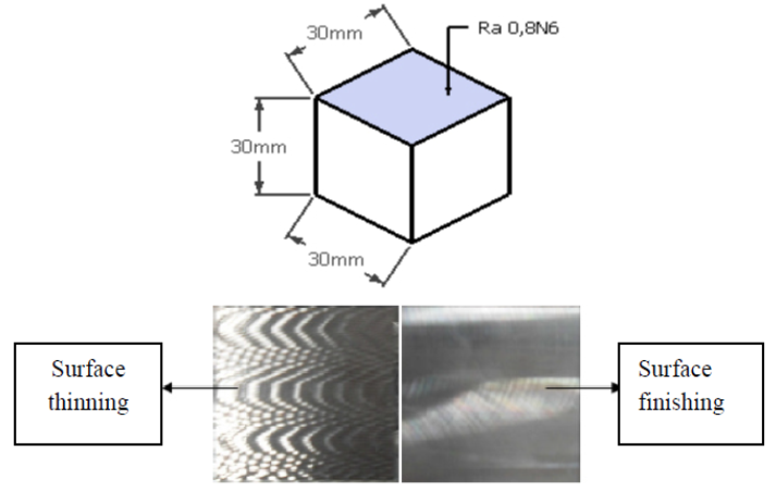 | Figure 1. Measurements of the specimen and surface finish obtained after milling (authorship) |
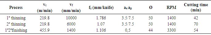
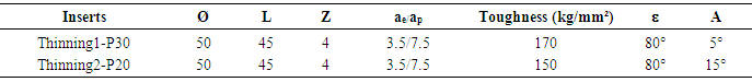
For all the experiments performed in this work, the cutting parameters of the roughing and finishing followed the conditions, considering the material to be machined and the type of tool applied (as to its geometry and coating). These parameters are described in Table 1.Table 1. Cut parameters used in experiments
 |
| |
|
The cut-off parameters for f, ap, Ø, RPM, cut-off time, were collected in the CNC programming memory of the machine and in the cutter and insert assemblies, considering these invariant values for each process, and variables between the processes, as recorded in Table 1.For the calculation of vc (Cutting speed), Eq. (1) was applied.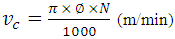 | (1) |
Where: vc = Cutting speed π = 3.1416Ø = Diameter of the cutterN = rotations per minute (RPM)For calculation of fz (feed per tooth), Eq. (2) was applied.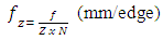 | (2) |
Where: fz = cutting edge advancef = table advanceZ = number of edgeN = rotation per minute (RPM) The roughing and finishing processes were monitored simultaneously with the recording of the flank wear measurements VB, to the condition of changing the insert by loss of the cutting edge (in the case of the finishing insert), and by faults in the surface of Clearance and at the cutting edge (in the case of the roughing insert). The SA 4600 optical microscope, supplied by SANDVIK, with a 10x magnification, was used to record flank wear measurements, although scanning electron microscopy was used to analyze the mechanisms of wear and characterization of defects in the inserts, it was also associated the image generated in the "Scanning Electron Microscopy" (SEM) to validate the records obtained by reading the optical microscope, more subject to parallax and hysteresis errors.The machine tool used was a machining center ROMI D1500, maximum rotation 12 000 RPM and nominal power of 30 hp, controlled by CNC SIEMENS 828D. The fastening system of both the test body and the set of machined bearings of the rail rails are considered rigid by the application of lateral, longitudinal and transverse devices along the side sections of the machined objects.For the first thinning process, four interchangeable inserts were used in TiAlN PVD, ISO P30, triangular, α = + 5°, negative (λ = -5°) Shown in Figure 2 (a), and sized in Table 2.Table 2. Main dimensions of milling cutter and P30 and P20 thinning inserts
 |
| |
|
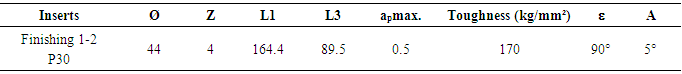
For the second thinning process, four interchangeable inserts were used in TiAlN PVD, class ISO P20, triangular, with α = + 15°, negative (λ = -5°), fitted with a Ø50mm cutter. Table 2 shows the main dimensions of the assembled set for the roughing insert of the analyzed process.The tools used for the finishing process were 04 rectangular prismatic interchangeable carbide inserts with TiN PVD, class P30, with a positive tool tip 90° mounted on a Ø 44 mm cutter. Table 3 shows the main dimensions of the set assembled for the finishing insert of the analyzed process.Table 3. Main dimensions of milling cutter and finishing insert
 |
| |
|
4. Results and Discussion
The first experiment was carried out to test the hardness of the roughing and finishing inserts and to compare them with the hardness of the MnSi alloy steel coating on 1020 steel substrate. The results of the hardness tests were obtained according to ASTM E-18, in DIGIMESS bench to durometer. In Figure 3 it is possible to observe the strength of the machined material and its analyzed inserts.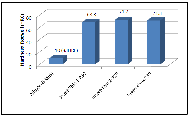 | Figure 3. Comparison between the results of the hardness tests performed on the machined material and the inserts under study, according to ASTM E-18 (authorship) |
Comparatively, a favorable cutting condition is observed, promoting the mechanism of chip formation without problems, both in thinning and in finishing, due to the high hardness of the inserts in relation to the hardness measured on the surface to be machined.The machined set to be analyzed in this process is shown in Figure 4, with the respective sequence of the roughened and finished surfaces, machined by the roughing inserts and the finishing inserts. The characterization of each part of the process was performed using "Scanning Electron Microscopy" (SEM). In the case of the analyzed surface, it was necessary to make a standardized test body following the same machining parameters of the bearings and maintaining the same composition of the substrate SAE 1020 and the MnSi coating.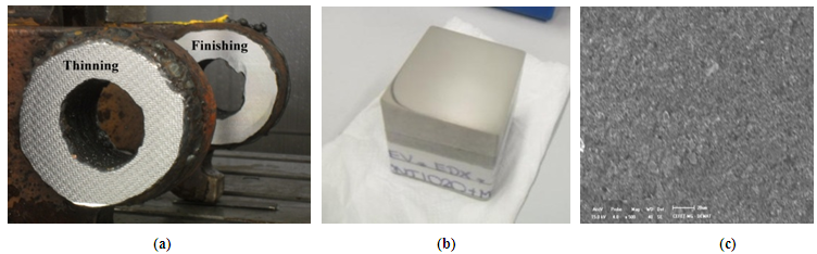 | Figure 4. (a) Bearing with roughened surfaces and final finish, (B) CP prepared for microscopic analysis and (C) Image generated by SEM of the test-increase body 500x (own authorship) |
The requirement of a low roughness and high abrasion resistance surface finish requires a material with mechanical properties of restricted variations, especially with respect to the obtained surface hardness (SHACKELFORD, 2015; CALLISTER, 2012). The microstructure of the MnSi deposition alloy on the 1020 steel substrate is composed of pores in small proportions (black areas), formed oxides In the deposition process (light gray areas) and the metallic phase with the highest proportion in the image fraction (dark gray area), the detailed chemical composition of the surface of the machined material also depends on a more specific analysis, which in this case will be performed by "Energy Dispersive X-ray Detector" (EDS) assay medium to quantify the percentage of each element composing the alloy deposited on the substrate in question.The roughing inserts applied in the machining have a slow initial wear due to the high resistance of the coating layers (SANTOS and SALES, 2007). This wear can reach between 0.3 mm and 0.4 mm, this is referenced in ISO 3685-1993, from then the cutting of the Material is made by the substrate, and consequently the wear of the tool grows rapidly, favoring the beginning of breakdowns at the cutting edge, and the exit and clearance surfaces (DINIZ et al., 2010).In Figure 5 with increase 20x, the profile of the roughing insert P30 with initial chipping propagating from the cutting edge (a) to the clearance surface (b) is observed, characterizing the loss of the coating after flank wear, reaching the substrate of the A tool that is usually composed of metal cabbages, mainly formed with tungsten. In Figure 5(c) it is possible to observe the progression of flank wear (VB) at the cutting edge, propagating from 0.2 mm the beginning of chipping failure in the direction of the cutting edge to the clearance surface, Negative depth of the tool, with a clearance angle of 5º, and with an ap of 7.5 mm, and finally the collapse of the insert with sharp plastic deformation on the clearance surface (d). | Figure 5. (a) New cutting edge; (B) Cutting edge with 0.2 mm flank wear and start of chipping; (c) Cutting edge with 0.3 mm VB and propagation of the chipping to the clearance surface; (d) collapse of the insert after 0.3 mm VB |
In Figure 6 is shown the profile of the thinning insert P20 (a) with chipping failure starting from 0.2mm of sidewall wear (b), propagating from 0.2 mm, thus generating the chipping in the direction of the cutting edge to the outlet surface (c), this direction being justified by the negative roughing tool characteristic, with α = 15°, and finally collapsing the insert with cracks and breaking from the outlet surface (d).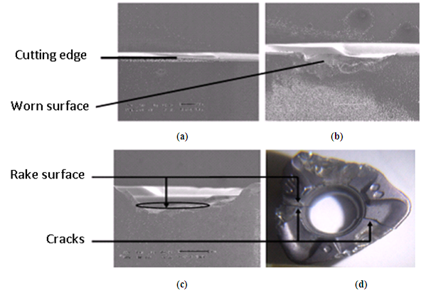 | Figure 6. (a) New cutting edge (increase 20x); (b) Cutting edge with 0.1 mm flank wear (VB) and start of chipping (increase 20x), (c) Cutting edge with 0.15 mm VB and spreading of chipping to exit surface (increase 20x), (d) collapse of the insert after 0.15 mm VB(increase 8x) |
In Figure 7 is shown the average curve of flank wear for the set of inserts assembled for the roughing processes performed, associated with the respective standard deviations. The class of tools P30 (thinning 1 - 1st group of inserts), with lower hardness, present greater initial wear with gradual growth from the 2nd cycle in the evolution of the wear. The class of tools P20 (thinning 2 - 2nd group of inserts), with greater hardness, present lower initial wear, followed by a marked growth from the second cycle in the wear evolution.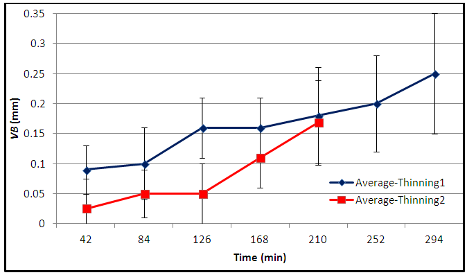 | Figure 7. Monitoring of sidewall wear of the roughing inserts used. (authorship) |
The finishing inserts applied in the machining of the bearings are changed piece by piece, therefore for these inserts it was not possible to make a monitoring of the wear of the flank obtaining a curve for the propagation of this type of wear. Figure 8 (a) shows the 0.10 mm flank wear of the finishing insert used after roughing with the P30 insert. Figure 8 (b) shows the 0.20 mm flank wear(VB) of the finishing insert used after roughing with the P20 insert.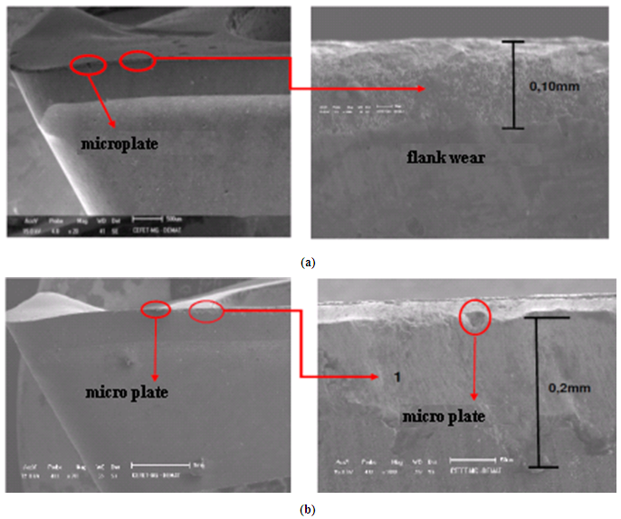 | Figure 8. (a) Flank wear (VB) of the 1st set of finishing inserts (increase of 20x and 1000x). (b) Flank wear (VB) of the 2nd set of finishing inserts (increase of 20x and 1000x) |
The finishing inserts were monitored simultaneously to the flank wear control of the roughing inserts, after finishing the roughing process the finishing process is executed, with 04 prismatic inserts mounted on a Ø44 mm milling cutter, in this particular process it is The insert was changed to each machined part, even if it has only normal flank wear per time of use, due to the need to obtain a surface and dimensional accuracy required by the customer.In figure 9 it is seen the flank wear measured in the finishing inserts with the relation of the cutting edge for a part, that is, it is a discrete characteristic measurement, where the cutting edge used in part 1, does not will be used in part 2, and so on, it is not possible to obtain a valid curve for the flank wear of the finishing process as a function of time.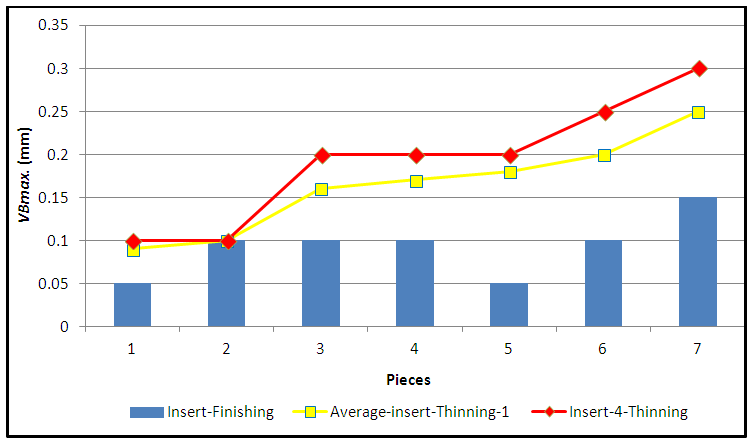 | Figure 9. VB measurements. Of the finishing inserts measured by machined part by insert P30 (authorship) |
The roughing insert P30 of the 1st experiment (Fig.9) is replaced on average between the 6th and 8th machined parts in an average time between 252 and 336 min. Replacement of the insert, or inversion of the cutting edge, occurred with the edge wear of 0.3 mm from the cutting edge of the insert 04, the average wear was 0.25 mm. When a chipping process begins at the cutting edge and crater on the clearance surface, which if disregarded will lead the tool to total collapse, compromising the machined surface.In figure 10 it is seen the flank wear measured in the finishing inserts with the relation of the cutting edge for a part, that is, it is a discrete characteristic measurement, where the cutting edge used in part 2.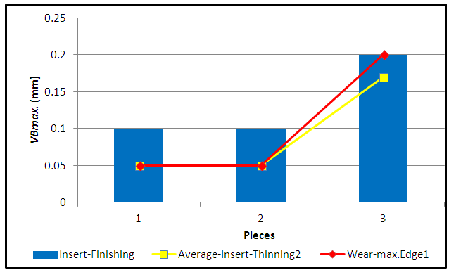 | Figure 10. VB measurements. Of the finishing inserts measured by machined part by insert P20 (authorship) |
The thinning insert P20 of the 2nd experiment (Fig.10) is replaced after machining of the 3rd part in a cut-off time of 210 min. The change of the insert, or the cutting edge, occurred with flank wear of 0.2 mm of the cutting edge of the insert, the average wear was 0.17 mm, when a process of degradation at the cutting edge and chipping and Cracks in the output surface, which if ignored will lead the tool to total collapse by cracking and breaking during the process.The rapid degradation of the cutting edge of the finishing insert during machining of 1 (one) piece with an average machining time of 54 min. Compromises the use of this tool in another part to be machined, ask; The study and monitoring of the flank wear of the thinning inserts, aims to identify possible causes that compromise the useful life of the finishing insert. This hypothesis of the possible wear relationship of the different inserts can be verified by analyzing and comparing the measurement results between the roughing and finishing flanks wear in the graphs of Fig.10, it can be observed in this graph the upward and cyclic progression Of the flange wear of the roughing insert between 0.1 and 0.2 mm (1st cycle), and between 0.2 and 0.3 mm (2nd cycle), which coincidentally occurs with flank wear of the inserts (Individually analyzed per piece), which also show up wear in the ranges of the wear cycle of the roughing inserts.The same integrated analysis for the graph of Fig.10 was performed, and the hypothesis of the possible wear relationship of the different inserts can be proven by analyzing the results of measurements between roughing and finishing flanks wear, it can be observed In this graph the upward progression of the edge wear of the roughing insert between 0.05 and 0.2 mm, and the occurrence of flank wear of the finishing inserts (individually analyzed per part), which also wear upward in the ranges of the cycle of thinning machining between 0.1mm and 0.2 mm.
5. Conclusions
Based on the obtained results it can be concluded that:§ For a comparative analysis, between slabs and finishes, we have a relation in the ascending and cyclical progression of the wear and tear between the processes.• For comparative analysis, between slabs and finishing, we have a relation in ascending progression and cyclical progression of the wear and tear between the processes.• For comparative analysis (between thinning 1 and thinning 2), thinning 1: inserts P30 with higher initial wear and evolution of this wear with gradual growth up to 294 min; In thinning 2: P20 inserts with minor initial wear followed by evolution with sharp growth up to 210 min.• The inserts of the 1st group presented more favorable conditions in the joint analysis of the processes, characterizing that the class P30 for thinning with α = 5°, coating of TiAlN PVD, contributed to a lower flank wear of the applied finishing tools, compared to the performance Of the thinning inserts of the 2nd group observed.• The mechanisms of wear and failure for the inserts of the 1st and 2nd groups were:In the thinning 1 Si adhesion and abrasion occurred, posterior collapse by chipping and diffusion on the clearance surface. In finishing 1, Si adhesion and abrasion onset occurred with normal VB without failures. In the thinning 2 Si adhesion and abrasion occurred, posterior collapse initiated by crater on the exit surface, propagating in chipping and cracking. In finishing 2, Si adhesion and abrasion were more pronounced than the 1st group inserts, with normal VB and microlasks at the cutting edge.
ACKNOWLEDGMENTS
To the company SuperMETAL in the city of Governador Valadares-MG Brazil, for the accomplishment of the experiments and data collection in the machining center, the CEFET-MG -Centro Federal de Educação Tecnológica de Minas Gerais- and IFMG-GV -Instituto Federal Minas Gerais-Campus Governador Valadares- for the availability of equipment and laboratories for the accomplishment of the measurements and tests, and SANDVIK for the technical support during the accomplishment of the experiments, measurements and analyzes.
References
| [1] | ASTM E-18. Standard Test Methods for Rocwell Hardness of Metallic Materials. American Society for Testing and Materials, Book of Standards, 2003. |
| [2] | Callister, W. D. Jr.. Science and engineering materials: an introduction. Department, John Wiley & Sons, Inc., 605 Third Avenue, New York.Seven Edition, 2012. |
| [3] | Diniz, A. E.; Marcondes, F.C.; Coppini, N.L. Tecnologia da usinagem dos materiais. 8 ed. São Paulo: Edit Artliber, 2013. |
| [4] | Ferraresi, D. Fundamentos da usinagem dos metais.5 ed. São Paulo: Edit Blucher, 1977. |
| [5] | Iscar Catalog. Millings tools. Metric Version Catalog, 2012. |
| [6] | ISO 3685. Tool life test with single point tuninng tolls. International Standardization Organization, 1993. |
| [7] | ISO 4287. Geometric specifications of the product (GPS) - Roughness: profile method - Terms, definitions and parameters of roughness. International Standardization Organization, 1997. |
| [8] | Machado, A.R; Abrão, A.M.; Coelho, R.T.; Silva, M.B. Teoria da usinagem dos materiais. 1 ed. São Paulo: Edit Blucher, 2009. |
| [9] | Sandvik Coromant. Rotatig in Tools: Milling, Drilling, Boring, Rotatiging Tool Adaptiors. Sandvik Group Headquarters, Sweden, 2017. |
| [10] | Santos, S. C.; Sales, W. F. Aspectos tribológicos da usinagem dos materiais. 1 ed. São Paulo: Edit Artliber, 2007. 246p. |
| [11] | Shackelford, J. F. Introduction to materials science for engineers. University of California, Davis. — Pearson Prentice Hall: Eighth Edition, 2015. |
| [12] | Trent, E.M., Wrigth, P.K. Metal Cutting, 4rd Edition, Butteworths-Heinemann Ltda. 2000. |

 Abstract
 Reference
 Full-Text PDF
 Full-text HTML