K.G.C. Senarathna1, 2, 3, R.M.G. Rajapakse1, 2
1Department of Chemistry, Faculty of Science, University of Peradeniya, Sri Lanka
2Postgraduate Institute of Science, University of Peradeniya, Sri Lanka
3Department of Biosystems Technology, Faculty of Technological Studies, Uva Wellassa University, Badulla, Sri Lanka
Correspondence to: K.G.C. Senarathna, Department of Chemistry, Faculty of Science, University of Peradeniya, Sri Lanka.
| Email: |  |
Copyright © 2018 The Author(s). Published by Scientific & Academic Publishing.
This work is licensed under the Creative Commons Attribution International License (CC BY).
http://creativecommons.org/licenses/by/4.0/

Abstract
Fuel cell (FC) is a good alternative energy source that can efficiently generate electricity by consuming fuels and oxygen. There are several different types of fuel cells. Hydrogen and methanol are the some of the common fuels used in FCs and molecular oxygen is the typical oxidant. Both hydrogen and oxygen can be synthesized by electrolysis of water or using photo-catalytic processes. Methanol can be produced using the reaction between H2 and CO2 and, hence, FCs stand out as sources of energy generation in a greener way. However, slow kinetics of cathode half-reaction and expensive platinum-based catalysts used for both electrodes are the barriers for FCs to become popular energy sources. Hence, our studies in this abstract concentrate on developing cheap materials to be used as oxygen reduction electrocatalysts. Simple chemical processes were developed to prepare conducting nanocomposites. Cerium(IV)-intercalated montmorillonite [Ce(IV)-MMT] was used for the spontaneous polymerization of aniline, pyrrole or 3,4-ethyldioxythiophene (EDOT), separately, in between clay interlayers. Ce(IV) cations are then reduced to Ce(III) state, while aniline, pyrrole and EDOT monomers are converted to polyaniline (PANI), polypyrrole (PPY) and poly(3,4-ethylenedioxythiphene) (PEDOT), respectively. The resulted three different Ce(III)/MMT/Conducting polymer composites have been extensively characterized by X-ray diffraction (XRD), X-ray fluorescent (XRF) spectroscopy, Fourier transform Infrared (FT-IR), Conductivity, Impedance and Electrochemical analyses. Then, morphological characterizations were done and the electrocatalytic activities of all systems were investigated for their oxygen reduction ability. Characterizations done for Ce(III)/MMT/PANI, Ce(III)/MMT/PPY and Ce(III)/MMT/PEDOT prove that polymers and cations are intercalated into the MMT inter-layer spaces. Composites are dehydrated after the polymerization. Conductivities of Ce(III)/MMT/PANI, Ce(III)/MMT/PPY and Ce(III)/MMT/PEDOT are 0.29, 0.18 and 0.22 S m-1, respectively. Electrochemical studies show that composites are good candidates towards oxygen reduction reaction (ORR) in acidic electrolyte medium. Ce(III)/MMT/PEDOT system shows the best performance among them. As such, these low-cost catalysts can be used as ORR catalysts in fuel cells.
Keywords:
Fuel cell, Electrocatalyst, Catalyst, Oxygen Reduction Reaction, Montmorillonite
Cite this paper: K.G.C. Senarathna, R.M.G. Rajapakse, Low-Cost Oxygen Reduction Electrocatalysts Based on Ce(III)/Electronically Conducting Polymer Montmorillonite Composites as Cathodes in Phosphoric Acid and Proton-Exchange Membrane Fuel Cells, Journal of Mechanical Engineering and Automation, Vol. 8 No. 2, 2018, pp. 39-48. doi: 10.5923/j.jmea.20180802.01.
1. Introduction
Electronically conducting polymers (ECPs) such as polypyrrole (PPY), polyaniline (PANI) and poly(ethylenedioxythiophene) (PEDOT) have received widespread attention of research and development community due to their innumerable different possible applications in electronic devices, biosensors and in many other advanced technologies. As such, the discoverers of ECPs have received Nobel Prize in Physics in the year 2000. [1] Unlike other electronically conducting materials, such as metals and inorganic semiconductors, EPCs have properties of polymers with wide range of electrical conductivities for the same material under varying doping conditions. As such, the same material can be doped to different extents to have insulating, semiconducting and even fully conducting properties. These different forms of ECPs have excellent mechanical flexibility and high thermal conductivity also. [2-4] As such ECPs have been explored for applications as conducting glasses and plastics for developing various electronic devices and shown to have improved mechanical, thermal and electrical properties over doped metal oxide electronic conductors such as tin(IV) doped indium oxide (ITO), fluorine-doped tin oxide (FTO) and so on. ECPs have also been explored for rugged applications such as LED lighting and electrical super capacitors. ECPs also have reversible electrochromic properties and hence they find applications in electrochromic display devices. Typically inherent properties of ECPs have been explored for applications as chemical sensors, biosensors, electronic noses, actuators, antistatic coatings, and microwave absorbent coatings, printed circuit boards, radar absorbent coatings, and electromagnetic shielding coatings, corrosion-resistant coatings as so on. [5-9] However, ECPs are not entirely free of drawback. One of the major drawbacks of ECPs is their poor processibility due to their insolubility in common solvents, acids and bases. As such, novel trend is to develop nanostructured forms of conducting polymers capable of making stable dispersions which could be used to process ECP nanomaterials into required forms such as thin films. With the development of stable nanoscale dispersions of PANI and PEDOT their processability has been improved and PEDOT/PSS (PSS = Poly(styrene sulphonate) dispersions are used in fabricating antistatic coatings and electronically conductive surfaces. Processable PANI is used to make printed circuit boards and anticorrosive layer on metals such as copper. [10-12]Some of the drawbacks associated with pristine ECPs can be overcome by intercalating ECPs in smectite clay such as montmorrilonite (MMT). We have been pioneered in synthesizing MMT-ECP nanocomposites and we have introduced a novel method to in situ polymerize ECPs within the interlayer spaces of MMT. We made use the ion-exchange properties of MMT to exchange oxidizing cations capable of oxidatively polymerizing monomers such as PPY, PANI and PEDOT for Na+ ions that are present within the interlayer spaces. We then introduced monomers of ECPs to aqueous suspensions of the ion-exchanged MMT to intercalate monomers into the interlayer spaces. These monomers were then found to oxidatively polymerize by the oxidizing cations such as Ce(IV), Co(III), Ag+, Hg22+ and so on forming composites of Reduced Form of the Cation/ECP/MMT. [13] These composite materials were extensively characterized by several independent analytical techniques and their possible technological applications were explored. Most of these materials were found to have excellent catalytic properties towards the oxygen reduction half-reaction. As such, these materials are excellent candidates for the cathodes of fuel cells. We have already demonstrated the applicability of Ce(III)/PPY/MMT, Co(II)/PPY/MMT, Co(II)/PANI/MMT, Co(II)/PEDOT/MMT and Ag(0)/PPY/MMT as oxygen reduction catalysts in fuel cells to replace expensive C/Pt catalysts that are currently used. [14, 15] As such, we have already demonstrated that low-cost fuel cells could be manufactured for applications in powering remote stations where national grid is not available and for applications in automobile industry. In this publication we reveal the synthesis and characterization of Ce(III)/PPY/MMT, Ce(III)/PANI/MMT and Ce(III)/PEDOT/MMT composite materials and their applications as low-cost cathodes of fuel cells. Interestingly, Co(II)-based composite catalysts show best performance in alkaline fuel cells but Ce(III)/ECP/MMT composites show best performance in acidic media but not in alkaline media. Reasons for this behavior will also be addressed.
2. Experimental
2.1. Chemicals Used
Bentonite clay (Sigma), aniline (99.5%, Sigma-Aldrich), pyrrole (99.0%, Sigma-Aldrich), EDOT (97.0% Alfa Aesar), Cerium sulphate (98.0%, Vickers), acids and bases (VWR Chemicals), H2O2 (30% in water, Sigma-Aldrich), ammonia (30% in water, VWR Chemicals) were used and the chemicals were further purified as and when necessary. For example, Bentonite was purified according to the procedure given below and the monomers such as aniline, pyrrole and EDOT were purified by reduced pressure distillation prior to use.
2.2. Characterization Techniques
X-ray diffraction (XRD) analysis was performed to identify the crystalline phases of raw samples and synthesized products and the diffractogrammes were obtained from Siemens D5000 X-ray powder diffractometer with Cu Kα radiation of wavelength, λ = 0.154 nm and at scan rates of 1° or 2° min-1. The XRD patterns were analyzed using ICDD PDF 2 database with the aid of X-powder 12 software. The 2θ range 3°-15° was chosen for the comparison of d values of interlayer spaces of MMT. Every sample was dried, at 150°C, for 2 h, and then again XRD patterns were taken to determine thicknesses of interlayer spaces of MMT containing anhydrous cations. The qualitative analyses for elements (those with atomic numbers higher than that of Aluminium) of natural and synthetic samples were performed from Fisher X-ray Fluorescence (XRF) instrument for powdered samples. These data are used to compare the atomic ratios of the selected two or more elements that are present in the samples. The morphology and the particle size of products were examined from Hitachi SU6600 Scanning Electron Microscope (SEM) at an acceleration voltage of 10 kV and from Leo 1530 VP Field Emission Gun Scanning Electron Microscope (FE-SEM) at an accelerating voltage of 5 kV. EDX analysis was also done for selected points of SEM images to identify the elements present in the sample and thereby to get an idea about the elemental ratios. FT-IR spectra of powdered samples were examined on a Shimadzu IR prestige 21 instrument with the aid of the KBr pellet method. In the preparation of KBr pellets, the sample was mixed with KBr at the mass ratio of sample: KBr of 1:40 and pressed at a pressure of 5 tonnes. The prepared pellets were well dried in a desiccator to remove physically adsorbed water, prior to analyses. Thermogravimetric analysis (TGA) of the samples were performed using Scinco STA N-650 simultaneous thermal analyser at a heating rate of 10°C/min, in an air flow, as well as under nitrogen gas purged conditions. X-ray Photoelectron Spectroscopy (XPS) of synthesized composites were characterized using Axis Ultra DLD X-ray Photoelectron Spectrometer and the data were re-plotted and the de-convolution of bands were done using CasaXPS 2.3 and Origin pro 8.0 Software. Powdered products were pressed at a pressure of 7 tonnes to prepare pellets with the surface area of 0.143 cm2. The thickness was varied as required. The prepared pellets were well dried in a dry desiccator to remove physically adsorbed water prior to analyses. Prepared pellet was sandwiched in two stainless steel rods with same surface area and a voltage of 0.1 V was applied to the two ends of stainless steel rods and the current was measured. Then the conductivity was calculated according to Ohms law. The four-probe conductivity measurements were done according to the method introduced by van der Pauw et al. [16] Gold-coated chromium spring contact probes together with low resistivity meter (measuring range 10 µΩ to 2 k Ω) were used to construct the instrument. Voltage was applied into two probes and the current was measured trough the other two probes and the sheet resistance was measured using a low resistivity meter. Same procedure was repeated by applying voltage to latter two probes and measuring current using former two probes. To carry out the electrochemical studies, working electrode was prepared according to the following procedure. The catalyst (10 µg) was dispersed in ethanol (2.00 mL) and Nafion (10 µl) was added. Then the mixture was soniccated for 10 min in order to obtain a well dispersed mixture which is hereinafter referred to as the catalytic ink. This catalytic ink (10 µL) was deposited on a well cleaned and polished glassy carbon (GC) electrode of 0.384 cm2 active surface area. [17] This electrode was used as the working electrode and cyclic voltammetry (CV) or linear sweep voltammetry (LSV) was run using Metrohm Potentiostat 101 and 204. Potentials were applied with respect to the saturated calomel electrode (SCE) and a Pt rod was used as the counter electrode. Scan rate used was 50 mV s-1. 0.10 M KOH(aq) or 0.50mol dm-3 H2SO4 electrolyte solutions were used as required. To measure the tolerance to methanol, KOH electrolyte was used in the presence of 0.100 M methanol. [18] Cyclic voltammograms were drawn using Nova 1.7 software and were re-plotted using Origin 8.0 pro software. All current densities were normalized to the geometric surface area of the disk electrode. LSV were done at rotating speeds from 600(±5) rpm to 2500(±10) rpm. AC impedance analysis was done using Metrohm Potentiostat 302 and Nyquist plots and Bode plots were drawn using Nova 1.7 software. [19]
2.3. Bentonite Clay Purification
Bentonite clay (20.0 g) was added to 0.10mol dm-3 hydrochloric (HCl) acid solution (800.0 cm3) and stirred for 24 h. The suspension thus obtained was centrifuged and the supernatant discarded. Resulted acid-treated clay was added to distilled water (800.0 cm3) and stirred for 24 h. The suspension obtained was centrifuged and the supernatant discarded. The upper part of the slurry was separated out and re-dispersed in distilled water. This procedure of dispersion, centrifuging and supernatant discarding was repeated several times to obtain fine particles of pure MMT. Then, the separated clay sample was dried in a regulated air flow under ambient temperatures. Pure MMT sample thus obtained was characterized by XRD and FTIR. Then powdered sample was heated at 150°C for 2 h and then again characterized by XRD.
2.4. Preparation of Ce(IV)/MMT
Ce(SO4)2 (20.63 g) was dissolved in 0.10 M H2SO4 solution (100.0 mL) to prepare 0.50mol dm-3Ce(IV) aqueous solution. MMT (1.00 g) was added to 0.50 mol dm-3Ce(SO4)2 solution (50.0 mL) and stirred for 48 h. The suspension obtained was centrifuged and the slurry of Ce(IV)/MMT was collected by discarding the supernatant. The sedimented material was dried under ambient conditions and powdered in an agate mortar and pestle. Powdered sample was characterized by XRD, XRF and FTIR. Then the sample was heated at 150°C for 2 h and then again characterized by XRD.
2.5. Synthesis of Ce(III)/MMT/PANI and Ce(III)/MMT/ PPY Composites
The procedure adopted in the synthesis of Ce(III)/MMT/PANI is as follows. Powdered Ce(IV)/MMT composite (0.500g) was dispersed in distilled water (25.0 mL) and the mixture was sonicated for 2 min. until the solid part is fully dispersed in the solution. Freshly distilled aniline (0.500 g) was dissolved in 1.0mol dm-3HCl solution (25.0 mL) and it was added to the Ce(IV)/MMT dispersion. Resulted mixture was stirred for 48h and the composite was separated by centrifuging followed by supernatant-discarding. The solid material thus obtained was washed with 0.10 M HCl solution then with acetone. The green colored precipitate thus obtained was allowed to dry under ambient conditions and the dried material was powdered in an agate mortar and pestle. In the synthesis of Ce(III)/MMT/PPY the same procedure was followed except that pyrrole was used instead of aniline. The samples were characterized by XRD (both at room temperature and after heat-treating at 150°C for 2 h), XRF and FTIR. Electrical properties of the material were determined by DC conductivity measurements and by AC impedance analysis. Their catalytic activities towards oxygen reduction half-reaction were elucidated by electrochemical techniques such as linear sweep voltammetry, cyclic voltammetry and rotating disc voltammetry.
2.6. Synthesis of Ce(III)/MMT/PEDOT Composite
Powdered Ce(IV)/MMT composite (0.10 g) was dispersed in 0.10 M HCl solution (10.0 mL) and the mixture was sonicated for 2 min. until the solid part is fully dispersed in the solution. Methanol (10.0 mL) was added and stirred. Then, 3,4-ethylenedioxythiophene (65 µL) was added while stirring and stirring was continued for 48 h. The composite thus obtained was separated by centrifuging followed by supernatant-discarding and washed with distilled water and then with acetone. The blue colored sample obtained was allowed to dry under ambient conditions and powdered in an agate mortar and pestle. All characterizations were done as stipulated in the characterization methods.
3. Results and Discussion
3.1. XRD and XRF Analyses of Materials
X-ray diffractogrammes of pure MMT, Ce(IV)/MMT and Ce(III)/MMT/PANI, after heating at 150°C for 2 h, in the 2θ range where MMT is showing (100) diffraction are shown in the Figure 1(a) and the comparison of the XRD peaks corresponding to diffraction from the (100) plain of Ce(III)/MMT/PPY, Ce(III)/MMT/PEDOT and Ce(IV)/MMT, after heating at 150°C, for 2 h, is shown in Figure 1(b).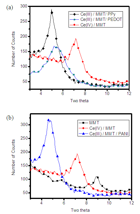 | Figure 1. XRD patterns, in the 2θ range where MMT is showing (100) diffraction, after heating at 150°C for 2 h, of (a) MMT, Ce(IV)/MMT and Ce(III)/MMT/PANI (b) Ce(IV)/MMT, Ce(III)/MMT/PPY and Ce(III)/MMT/PEDOT |
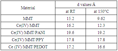
The d-spacing values extracted from diffractions from the (001) plain of MMT in composites as well as that of purified MMT are depicted in Table 1 MMT shows basal spacing variations in certain levels such as 18 Å, 15 Å, 12 Å and 9Å due to the presence of three, two, one and zero water layers within its interlayer spaces, respectively However, smectite clays can expand when the foreign materials such as polymers come into the layer spaces. Since the d-spacings of MMT depend strongly on the number of water layers present around ions, d-values of MMT products formed at RT cannot be used in comparison purposes. Therefore, water present within the interlayers should be removed and this can be done by heat-treating MMT products at 150°C, for 2 h prior to recording XRD patterns.Table 1. d-spacing values extracted from X-ray diffractions from the 001 plain of purified MMT and of cerium-based composites
 |
| |
|
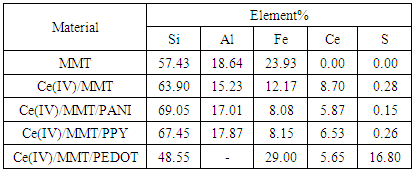
After stirring MMT with Ce(IV) ions, Ce(IV) ions can exchange for the soluble cations present in the interlayer spaces of MMT. This changes the d value obtained from (001) diffraction from 15.2 Å to 16.2 Å at ambient laboratory conditions. Since these ions could accompany different numbers of water layers comparison of these d-values is not possible. However, when heat-treated at 150°C for 2 h, d value of purified MMT and Ce(IV)-exchanged MMT are 9.62 Å and 12.3Å, respectively. Although the size of Ce(IV) ionic radius (0.97 Å) is not considerably larger than that of Na+ ions (1.91 Å) [20, 21] the observed d-value of Ce(IV)-exchanged MMT is lager by 2.69 Å than that of pure MMT. This may be due to hydrolysis of intercalated [Ce(H2O)6]4+(aq) ions forming CeO2 inside the interlayer spaces. Spontaneous polymerization of aniline, pyrrole or EDOT within the interlayers of Ce(IV)-MMT results in the increment of d values to 19.6Å, 17.8Å and 17.2Å, respectively. The products obtained after the polymerization were Ce(III)/MMT/PANI, Ce(III)/ MMT/PPY and Ce(III)/ MMT/PEDOT and their basal spacing of (001) plain do not reduce considerably even after the heat treatment at 150°C since the presence of these polymers within interlayer spaces make the interlater dehydrated. This happens due to the removal of water inside the layer space while polymerization is taking place. This gives an indirect proof to the presence of polymers within the inter-galleries of MMT in their anhydrous form.According to XRF data depicted in Table 2, Ce(IV)/MMT has 8.70% of Ce (These percentages have been calculated by measuring the amounts of Al, Si, Fe, S and Ce only. Elements with atomic number less than 13 are not detectable by XRF studies). This shows that Ce(IV) ions are readily intercalated within the interlayers of MMT and are coordinated by the negatively charged MMT layers via O- and OH sites. These Ce(IV) ions initiate the oxidative polymerization of aniline, pyrrole or EDOT. During these processes, Ce(IV) ions are converted to Ce (III) ions or Ce(0) metallic form. After the polymerization, relative abundance of Ce is reduced by nearly 2-3%. This may be due to the leaching out Ce(IV) ions from the nanocomposite and diffusing to the solution phase while the polymerization of monomers are taking place. Ce(IV)/MMT, Ce(IV)/MMT/PANI and Ce(IV)/MMT/PPY composites contain very small amounts of S also. This S must have been originated from the intercalation of sulphate ions into the interlayer spaces. Obviously, Ce(IV)/MMT/PEDOT contains a significant amount of S which comes mainly from S in PEDOT. Table 2. XRF data of purified MMT, Ce(IV)/MMT and Ce(IV)/MMT/ECP composites
 |
| |
|
3.2. FTIR Analysis
FTIR spectra of pure MMT, Ce(IV)/MMT, Ce(III)/MMT/PANI, Ce(III)/MMT/PPY and Ce(III)/MMT/PEDOT are shown in Figure 2.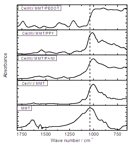 | Figure 2. FTIR spectra of pure MMT, Ce(IV)/MMT, Ce(III)/MMT/PANI, Ce(III)/MMT/PPY and Ce(III)/MMT/PEDOT |
Pristine MMT shows the IR absorption bands at 523 cm-1 and 466 cm-1 due to Si–O–Si and Si–O–Al deformation vibrations, respectively. The band for Si–O stretching appeared at 1031 cm-1. Al–Mg–OH deformation, Al–Fe–OH deformation, Al–Al–OH deformation is assigned to the peaks at 830 cm-1, 877 cm-1 and 915 cm-1 respectively. [22] Hydrogen bonded O–H stretching of water molecules inside the MMT layer spaces shows a broad band in the range 3200-3500 cm-1 of the FT-IR spectrum. The band at 3623 cm-1 is assigned to the interlayer and intralayer OH stretching or non-hydrogen bonded (free) OH stretching of water molecules. H–O–H bond bending is appearing at 1624 cm-1. [23] The characteristic bands of MMT is not disappeared or shifted when Ce(IV) intercalated MMT due to no structural changes to MMT has occurred as a result of ion-exchange. However, the band at 1031 cm-1, which is due to the Si–O stretching, is shifted to negative wave number when Ce(IV) ions or polymers are intercalated to the inter layers of MMT. This observation may due to the formation of new bonds between cerium and the negatively charges MMT layers. Water bending at 1640 cm-1 is also disappeared after the incorporation of polymers. All three Ce(III)/MMT/ Conducting-Polymer composites show low intensity of this peak and is due to the removal of water inside the layers when the polymerization has taken place as it was also revealed by XRD studies. This answers the question as to why there were no considerable changes in the d spacing of MMT layers shown even after heated at 150°C for 2 h. Hydrogen bonded O–H stretching at around 3400 cm-1 and free O–H stretching at 3622 cm-1 are narrowed in Ce(IV)/MMT and Ce(III)/MMT/PEDOT due to the water of coordination bond with Ce(IV) and Ce(III). In the Ce(III)/MMT/PPY and Ce(III)/MMT/PANI composites, these peaks are diminished in intensity when compared to the intensity of the new peak appeared at 3226 cm-1 which is due to H-bonded N-H stretching.
3.3. Conductivity Measurements and Impedance Analysis
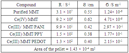
DC conductivity of the materials measured using 2-probe techniques are shown in Table 3. Both purified MMT and Ce(IV)/MMT have µS m-1 conductivities originating from movement of ions. However, all three Ce(III)/ECP/MMT composites have conductivities that are five orders of magnitude higher than those of the compounds without ECPs. Such high conductivities have originated from electronic and ionic conductivities of these ECPs. This shows that ECPs in these composites are present in their conducting forms.Table 3. DC conductivity data Resistance (R), Thickness (Ϩ) and conductivity (Ϭ) of materials
 |
| |
|
Nyquist plots of the electrochemical impedance spectra (EIS) of Ce(III)/ECP/MMT composites, in the frequency range from 0.1MHz to 1 MHz, under zero DC potential bias, are shown in the Figure 3(a). 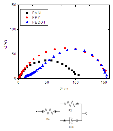 | Figure 3. (a) Nyquist plots obtained from EIS measurements of Ce(III)/ECP/MMT composites and (b) the Suggested equivalent Circuit |
These Nyquist plots contain small semicircle in the high frequency range corresponding to the resistance of the contacts, R1, and a large semicircle in the low frequency range which corresponding to the polarization resistance and the resistance of the materials, R2. However, these semicircles are not perfect semicircles but curves with lower Z” radii than Z’ radii. As such, a constant phase element (CPE) must be introduced to account for this fact. The materials have capacitances, C, also and hence the equivalent circuit corresponding to these Nyquist plots should have all these four circuit elements. As such, the most appropriate equivalent circuit proposed to account for these features is given in the inset of Figure 3(b). Conductivity of the materials can be extracted from R2 data and geometric parameters of the pellets used. These data are given in Table 4. Comparison of the conductivity data measured by two different techniques show that they are nearly equal for corresponding materials thus showing accuracies of the methods used to determine these conductivities.EIS studies were also carried out by making working electrodes of materials prepared by composites and Nafion binder deposited on glassy carbon (GC) electrode surfaces in the 0.5M H2SO4 electrolyte in three-electrode configuration. For comparison, EI spectrum of Pt/C at same mass loading as Ce(III)/ECP/MMT and Ce(III)/PPY/MMT at twice this mass loading were also recorded. The Nyquist plots obtained in the same frequency range are depicted in Figure 4(a) and the corresponding equivalent circuit is shown in Figure 4(b) [24, 25].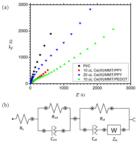 | Figure 4. (a) Nyquist plots of EIS in three-electrode configuration in 0.5 M H2SO4 solution for Pt/C and Ce(III)/ECP/MMT/GC working electrodes at open circuit potentials. (b) Modified Randles equivalent circuit used to fit the data points of the EIS spectra |
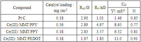
This circuit is derived by modifying the typical Randles circuit to account for features associated with these systems. Here, Rs denotes the bulk solution resistance, Rint is the interfacial resistance which is attributed to the high-frequency region and this resistance depends on the conductivity of the material used. Rct is the charge-transfer resistance at the interface between the electrode surface and the electrolyte and it appears in the low-frequency range. Cint is the interfacial capacitance and the Cdl stand for the double layer capacitance. Zw is Nernst diffusion impedance in the bulk electrolyte solution between the two identical electrodes. The values of these circuit elements calculated using Nova 1.10 fit and simulation procedures are given in Table 5.An ideal electrocatalyst should have low Rint and Rct values since low Rint promotes the diffusion of the electro-active materials to the surface of the electrode and its subsequent red-ox reaction. As revealed by the data in Table 5, Rint of Ce(III)/PPY/MMT is similar to that of commercial Pt/C (at 20% w/w Pt loading) but that of Ce(III)/PEDOT/MMT is much lower. Hence, by considering Rint values, it can be predicted that both composites may have either similar or better electrocatalytic activity than that of Pt/C. Rint alone does not indicate the suitability of materials as catalysts and Rct is also an important factor determining the diffusion of ions. Low Rct indicates lesser polarization of the electrode increasing the double layer capacitance. Rct value of Ce(III)/PEDOT/MMT is slightly larger than that of Pt/C and Ce(III)/PPY/MMT shows much higher values. Increasing the amount of Ce(III)/PPY/MMT loading has increased the Rct value. As such, higher catalyst loading is not required for catalytic properties of Ce(III)/PPY/MMT and, therefore, the standard catalyst loading of 0.18 g cm-2 that is used in commercial Pt/C catalysts were used for further electrochemical analyses as revealed below.Table 5. Rint, Rct, Cdl data extracted from the fitting of the EIS spectra to the proposed equivalent circuit
 |
| |
|
3.4. Catalytic Activities of Materials towards Oxygen Reduction
3.4.1. Cyclic Voltammetric (CV) Studies
Having characterized morphological and conducting properties of Ce(III)/ECP/MMT systems their electrocatalytic activities towards oxygen reduction reaction (ORR) were investigated by electrochemical methods. [14, 26] Although Co(II)/ECP/MMT systems show appreciable electrocatalytic properties towards ORR in alkaline media Ce(III)/ECP/MMT materials do not show good performance in the alkaline medium. This is due to the fact that Ce(III) is a strong reducing agent in alkaline media thus oxidizing to Ce(IV) even with atmospheric oxygen. [27, 28] As such, in alkaline media Ce(III) can be oxidized by the partially oxidized conducting forms of ECPs thus forming Ce(IV) and reduced forms of ECPs. These Ce(IV)/Reduced forms of ECP/MMT may not have electrocatalytic properties towards ORR. However, good performances are obtained in the acidic electrolytes. Hence, CVs were run for all three composites in N2 and O2 saturated 0.50 M aq. H2SO4 solutions at a scan rate of 50 mV s-1 and the pristine GC electrode and commercially available Pt/C (20% w/w Pt loading) electrocatalysts with the same mass loadings (~0.18 mg cm-2) were used studied under identical conditions for comparison purposes.Figure 5(a) displays the CVs of Ce(III)/ PANI /MMT in N2 and O2 saturated electrolyte environments in the potential range from -0.5V to +1.2V with respect to saturated calomel electrode (SCE). A current gain at around +0.2 V is observed in the O2 saturated 0.5 M aq. H2SO4 solution for Ce(III)/MMT/PANI in the cathodic sweep. This current gain disappears when the solution is saturated with N2 gas indicating that it is due to oxygen reduction. CVs also show that below -0.32 V of the cathodic sweep, a cathodic current gain is again observed which can be attributed to be due to H+ reduction.Figure 5(a) displays comparison of ORR catalytic activity of Ce(III)/PANI/MMT with those of GC and Pt/C electrodes. As depicted, a reduction peak for the Pt/C is observed at + 0.34 V with a current density of 0.97 mA cm-2. There is no cathodic reduction peak of Ce(III)/MMT/PANI at the potential range corresponding to the ORR of the Pt/C electrode. The first cathodic current gain is observed at -0.32 V corresponding to H+ reduction in the N2-saturated solution. However, this cathodic current density has increased in the O2 saturated environment indicating catalytic properties towards ORR of Ce(III)/MMT/PANI. Naked GC electrode does not show any redox waves in this potential range.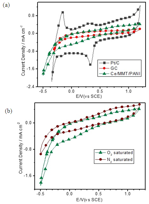 | Figure 5. Cyclic voltammograms (CVs) of Ce/MMT/PANI on glassy carbon (GC) electrodes in 0.5M H2SO4 solution at a scan rate of 50 mV s-1. (a) Comparison of CVs inN2 and O2 saturated environments. (b) Comparison with the pristine GC and commercial Pt/C electrodes |
Figure 6(a) shows the comparison of CVs of Ce(III)/MMT/PEDOT/GC with those of GC and Pt/C electrodes. Figure 5(b) compares CVs of Ce(III)/MMT/PEDOT/GC in N2 and O2 saturated electrolyte environments. Cathodic reduction peaks are observed at +0.47 V and 0.20V with a current density of 0.19 mA cm-2 and 0.16 mA cm-2, respectively for the Ce(III)/MMT/PEDOT/GC electrode in the O2saturated environment. The corresponding cathodic reduction peak for the Pt/C electrode is observed at + 0.31V with a current density of 0.92 mA cm-2 while the pristine GC does not show any peak in this potential range. Therefore, these CVs prove the catalytic properties towards ORR. However, when compared to the same loading of Pt/C, the peak current density is 4.8 times lesser for Ce(III)/MMT/PEDOT/GC than that of Pt/C. Increase of Ce/PEDOT/MMT catalytic loading on GC surfaces does not show considerable increment of cathodic peak currents and at the catalytic loadings over 0.7 mg cm-2 tend to reduce the catalytic property possibly due to increase in resistance of the electrode.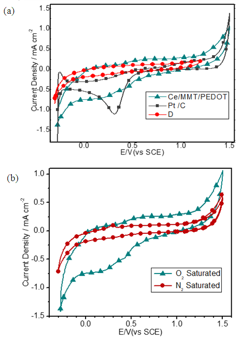 | Figure 6. Cyclic voltammograms (CVs) of Ce/MMT/PEDOT sample on glassy carbon (GC), Pt/C and naked GC electrodes in 0.5M H2SO4 solution at a scan rate of 50 mV s-1 (a) Comparison with the pristine GC and Pt/C. (b) Comparison of CVs of Ce/MMT/PEDOT sample on glassy carbon in N2 and O2 saturated environments |
Figure 7(a) depicts the CVs for Ce(III)/PPY/MMT and comparison of those of GC and Pt/C electrodes and Figure 7(b) shows the comparison of CVs of Ce/PPY/MMT sample on GC electrode in N2 and O2 saturated electrolyte environments all in the potential range from -0.3V to 1.2V wrt SCE. A cathodic reduction peak at + 0.41 V with a current density of 0.38 mA cm-2 is observed for Ce(III)/PPY/MMT on GC electrode in the O2 saturated environment showing electro-catalytic properties of Ce(III)/PPY/MMT towards ORR. This peak current density is 2.5 times lesser than that of ~0.18 mg cm-2 loaded Pt/C. Despite this lesser activity of Ce(III)/PPY/MMT as an electrocatalyst for ORR, it stands out to be excellent candidate to replace Pt/C as ORR catalytic cathodes of fuel cells since Ce(III)/PPY/MMT is very much cheaper than Pt/C. 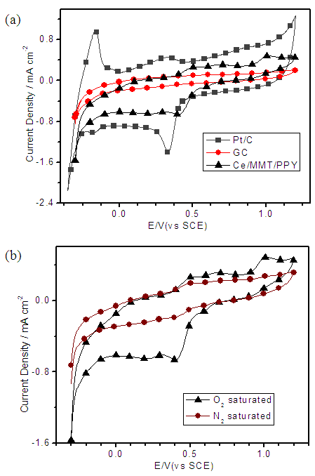 | Figure 7. Cyclic voltammograms (CV) of Ce(III)/PPY/MMT sample on GC electrodes in 0.5M H2SO4 solution at a scan rate of 50 mV s-1. (a) Comparison with the pristine GC, Pt (b) Comparison in N2 and O2 saturated environments |
3.4.2. Polarization Curves
In order to further study, the ORR performance of these electrocatalysts, we carried out the linear sweep voltammetry (LSV) measurements of all Ce-based electrodes, along with naked GC and commercial Pt/C electrodes, in O2 saturated 0.50 M H2SO4 solutions at a scan rate of 5mV s-1. As shown in Figure 7, the onset potential for oxygen reduction at the Pt/C electrode is +0.52V. Ce(III)/ECP/MMT on GC electrodes also show oxygen reduction near this potential. However, the current densities are lower than that of Pt/C. The current densities at 0.3 V for the pristine GC, Ce(III)/MMT/ PANI, Ce(III)/MMT/PEDOT, Ce(III)/MMT/PPY, and Pt/C electrodes are 0.3, 1.0 ,1.6, 1.9 and 4.7 mA cm-2, respectively. These current density values for Ce(III)/MMT/ PANI, Ce(III)/MMT/PEDOT, Ce(III)/MMT/PPY are about 3.3, 5.3 and 6.3 times, respectively, greater than that of GC electrode and are 21%, 34% and 40% of that of the Pt/C, respectively. However, the current densities at +0.10 V for the pristine GC, Ce(III)/PANI/MMT, Ce(III)/PEDOT/MMT, Ce(III)/PPY/MMT, and Pt/C electrodes are 0.3, 1.3, 2.1, 1.6 and 5.0 mA cm-2, respectively. These data are consistent with the CV data and confirm the significant contributions to the ORR electrocatalytic activity of Ce-based composites. 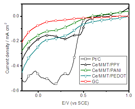 | Figure 8. Polarization curves for Ce-based composites deposited on GC electrodes together with those of Pt/C and naked GC electrodes in oxygen saturated 0.50 M H2SO4 solution |
4. Conclusions
Ce(III)/MMT/PANI, Ce(III)/MMT/PPY and Ce(III)/MMT/PEDOT composites were synthesized and characterized using XRD and XRF analysis. Results prove that the polymers and Ce cations are intercalated in to the MMT layers. Conductivity measurements of composites shows the conductivity of Ce(IV) intercalated MMT is increased from 4.71 × 10⁻⁶ S m-1 to 2.97 × 10⁻¹ S m-1, 1.77 × 10⁻¹ S m-1 and 2.15 × 10⁻¹ S m-1 by introducing PANI, PPY and PEDOT respectively. Impedance analysis of prepared electrodes of composites in 0.5M H2SO4 solution fit with suggested modified Randle’s equivalent circuit. Good polarization resistance are observed for Ce(III)/MMT/PPY and Ce(III)/MMT/PEDOT, however the charge transfer resistances are considerably at high value which are effected in lower catalytic properties towards ORR than Pt/C. Cyclic voltammetries and polarization curves are depicted that composites are good in catalytic activity towards ORR.
ACKNOWLEDGEMENTS
The authors gratefully acknowledge the financial assistance by Higher Education for Twenty first Century (HETC) Grant (Grant No. HETC/PGIS/QIG/W3-TOR10). The authors also thank Ms. N.I. Attanayake and Mr. Amara Sanjeewa Wijekoon (Technical officers at Department of Chemistry, University of Peradeniya) for their technical assistance.
References
| [1] | The Nobel Prize in Chemistry. http://www.nobelprize.org/nobel_prizes/chemistry/laureates/2000/index.html. |
| [2] | Sharma AK, Chaudhary G, Kaushal I, et al. Studies on Nanocomposites of Polyaniline Using Different Substrates. Am J Polym Sci 2015; 5: 1–6. |
| [3] | B. Kondawar S, D. Deshpande M, P. Agrawal S. Transport Properties of Conductive Polyaniline Nanocomposites Based on Carbon Nanotubes. Int J Compos Mater 2012; 2: 32–36. |
| [4] | Neetika G, D. K, S. K. T. Thermal Behaviour of Chemically Synthesized Polyanilines/Polystyrene Sulphonic Acid Composites. Int J Mater Chem 2012; 2: 79–85. |
| [5] | Ruhi G, Bhandari H, Dhawan SK. Corrosion Resistant Polypyrrole / Flyash Composite Coatings Designed for Mild Steel Substrate. Am J Polym Sci 2015; 5: 18–27. |
| [6] | Polyindole P, Shakshooki SK, Elejmi AA, et al. Synthesis and Characterization of Glassy Tin Composites Via In-Situ Oxidative Polymerization. 2016; 6: 87–94. |
| [7] | Yakhmi J V, Saxena V, Aswal DK. 2 - Conducting Polymer Sensors, Actuators and Field-Effect Transistors. Epub ahead of print 2012. DOI: http://dx.doi.org/10.1016/B978-0-12-385142-0.00002-7. |
| [8] | Kausar A. Effect of Halloysite Nanoclay on Polymerization and. Am J Polym Sci 2015; 5: 30–34. |
| [9] | Karmakar RS, Lu YJ, Fu Y, et al. Cross-Talk Immunity of PEDOT:PSS Pressure Sensing Arrays with Gold Nanoparticle Incorporation. Sci Rep; 7. Epub ahead of print 2017. DOI: 10.1038/s41598-017-12420-5. |
| [10] | Araujo WS, Margarit ICP, Ferreira M, et al. Undoped polyaniline anticorrosive properties. Electrochim Acta 2001; 46: 1307–1312. |
| [11] | Hwang YH, Chun HS, Ok KM, et al. Density Functional Investigation of Graphene Doped with Amine-Based Organic Molecules. J Nanomater; 2015. Epub ahead of print 2015. DOI: 10.1155/2015/917637. |
| [12] | Senarathna KGC, Mantilaka MMMGPG, Peiris TAN, et al. Convenient routes to synthesize uncommon vaterite nanoparticles and the nanocomposites of alkyd resin/polyaniline/vaterite: The latter possessing superior anticorrosive performance on mild steel surfaces. Electrochim Acta 2014; 117: 460–469. |
| [13] | Rajapakse RMG, Higgins S, Velauthamurty K, et al. Nanocomposites of poly(3,4-ethylenedioxythiophene) and montmorillonite clay: Synthesis and characterization. J Compos Mater 2011; 45: 597–608. |
| [14] | Rajapakse RMG, Murakami K, Bandara HMN, et al. Preparation and characterization of electronically conducting polypyrrole-montmorillonite nanocomposite and its potential application as a cathode material for oxygen reduction. Electrochim Acta 2010; 55: 2490–2497. |
| [15] | K.G.C. Senarathna, R.M.G. Rajapakse, P.S. Jayawardena, A. Kondo MS. Extremely Low-Cost Alternative for the Oxygen Reduction Catalyst of Fuel Cell. Adv Automob Eng 2015; 04: 1–6. |
| [16] | van der Pauw LJ. A method of measuring the resistivity and hall coefficient of discs of arbitrary shape. Philips Res Reports 1958; 13: 1–9. |
| [17] | Yao Z, Nie H, Yang Z, et al. Catalyst-free synthesis of iodine-doped graphene via a facile thermal annealing process and its use for electrocatalytic oxygen reduction in an alkaline medium. Chem Commun 2012; 48: 1027. |
| [18] | Xia M, Ding W, Xiong K, et al. Anchoring effect of exfoliated-montmorillonite-supported Pd catalyst for the oxygen reduction reaction. J Phys Chem C 2013; 117: 10581–10588. |
| [19] | Jia Z. Rotating Electrode Methods and Oxygen Reduction Electrocatalysts. Rotating Electrode Methods and Oxygen Reduction Electrocatalysts 2014; 199–229. |
| [20] | Thomas JB. Melt Inclusions in Zircon. Rev Mineral Geochemistry. Epub ahead of print 2003. DOI: 10.2113/0530063. |
| [21] | Wells AF. Structural Inorganic Chemistry. 5th ed. Oxford, 1984. |
| [22] | Bala P, Samantaray BK, Srivastava SK. Dehydration transformation in Ca-montmorillonite. Bull Mater Sci 2000; 23: 61–67. |
| [23] | Sogandares FM, Fry ES. Absorption spectrum (340-640 nm) of pure water. Appl Opt 1997; 36: 8699–8709. |
| [24] | Pang H, Wei C, Li X, et al. Microwave-assisted synthesis of NiS2 nanostructures for supercapacitors and cocatalytic enhancing photocatalytic H2 production. Sci Rep 2014; 4: 3577. |
| [25] | Jiang Z, Jiang Z, Tian X, et al. Amine-functionalized holey graphene as a highly active metal-free catalyst for the oxygen reduction reaction. J Mater Chem A 2014; 2: 441. |
| [26] | Senarathna KGC, Randiligama HMSP, Rajapakse RMG. Preparation, characterization and oxygen reduction catalytic activities of nanocomposites of Co(ii)/montmorillonite containing polypyrrole, polyaniline or poly(ethylenedioxythiophene). RSC Adv; 6. Epub ahead of print 2016. DOI: 10.1039/c6ra23100d. |
| [27] | Armes SP, Aldissi M. Potassium iodate oxidation route to polyaniline: an optimization study. Polymer (Guildf) 1991; 32: 2043–2048. |
| [28] | Ballard JR, Palin JM, Campbell IH. Relative oxidation states of magmas inferred from Ce“IV”/Ce“III” in zircon: Application to porphyry copper deposits of northern Chile. Contrib to Mineral Petrol. Epub ahead of print 2002. DOI: 10.1007/s00410-002-0402-5. |

 Abstract
 Reference
 Full-Text PDF
 Full-text HTML