Chandrashekar BK, Santosh Joteppa, Kiran R. Bakale, Vinod S. Chippalkatti
Design and Engineering, Centum Electronics Ltd., Bangalore, India
Correspondence to: Chandrashekar BK, Design and Engineering, Centum Electronics Ltd., Bangalore, India.
| Email: |  |
Copyright © 2017 Scientific & Academic Publishing. All Rights Reserved.
This work is licensed under the Creative Commons Attribution International License (CC BY).
http://creativecommons.org/licenses/by/4.0/

Abstract
Electronic equipment’s are manufactured with many types of Electronic components which are largely available as leaded and leadless mounting, these components are mounted on the PCB with through-hole or surface mounted technologies. The electronic equipment’s which are used in aerospace, space, military, commercial applications etc., have to undergo vibration and shock testing. When these equipment’s are subjected for such vibration requirements they are prone to fatigue failure and the primary failures will be observed at component leads and solder joints. These components need to be designed and used for rated fatigue loads with required vibration level to avoid such fatigue failures. HMC (Hybrid Micro Circuit) Packages are one among such leaded electronic components being widely used in space, aerospace and defense industries for various application to reduce the mass and volume. During the usage these leaded component experiences severe dynamic loads which may lead to fatigue failure at leads and solder joints. Thus, it is necessary to verify such electronic component life before they are subjected to dynamic load testing to save the time and huge cost. This paper describes the method of designing and analyzing the HMC package subjected for higher vibration loads and analytical method of fatigue life estimation. Subsequently, the HMC package has been manufactured and validated by subjecting it to the higher vibration load to find out the fatigue life and correlated with the analytical results.
Keywords:
HMC, Leads, Fatigue life, FEA, SN Curve, Transmissibility, Dynamic bending stress
Cite this paper: Chandrashekar BK, Santosh Joteppa, Kiran R. Bakale, Vinod S. Chippalkatti, Life Estimation of HMC Package under Dynamic Load Condition and Correlation of Analysis and Test Results, Journal of Mechanical Engineering and Automation, Vol. 7 No. 5, 2017, pp. 172-178. doi: 10.5923/j.jmea.20170705.09.
1. Introduction
Hybrid Micro Electronics deals with packaging and interconnection technologies for combining two or more semiconductor devices on a common interconnect substrate, typically to create a specific electrical function. The semiconductor devices may be in the form of bare, unpackaged die or in miniature packages which mount on the interconnect substrate surface. The interconnection pattern may include deposited resistors, capacitors, and inductors or these passive components may be mounted in chip form on the surface of the substrate [1, 2] refer Figure 1.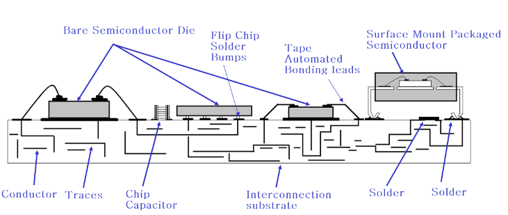 | Figure 1. Schematic diagram of cross section illustrating Hybrid microelectronics technology |
In Space, aerospace and defense application, the Hybrid microcircuits are extensively used over other forms of package for saving of space, volume and weight. As mass has direct effect on cost of payload launch, the use of microelectronics circuit’s helps in reducing the cost of these payload launch and electronics manufacturing.These microcircuit packages are manufactured using thick film technology, where the conductors, dielectric and resistor layers are deposited. These packages need to be qualified for high vibration and shock loads based on MIL or space application requirements. When these packages are mounted on PCB they will experience further amplification and it is necessary to understand the fatigue life of such components before finalizing the design for manufacturing [3].
2. Background
The HMC packages are one of the important electronic components in the hybrid microelectronic circuits as the major operations are performed by these HMC packages. Thus, for the better operation of any hybrid microelectronic circuits, these HMC packages should be designed/assembled in such a way that under any critical circumstance these packages should withstand loads without any damage. The major failures in the leaded components are observed at leads and solder joints [4-6]. Generally these failures are not immediate, but it is gradual due to continuously subjecting to a constant load which leads to fatigue failure. Thus estimation of fatigue life of HMC package is also an important parameter to be taken care during the design stage. Below section explains how the life of HMC package has been estimated by means of calculation using fundamental frequency and acceleration level obtained from finite element analysis. Subsequently the package has been manufactured and tested till failure to estimate the life. The analysis and testing results are discussed in detail in later sections.
3. Design Description
The HMC packages are available in standard sizes, based upon the output requirement, the substrate size shall be decided and based on the substrate and number of input/output requirement lead size will be decided. The basic construction of the HMC package consisting of multiple layers, able film [7] being placed at the bottom of package called package base upon that the substrate has been placed which is basically alumina [8], over the alumina, epoxy material is deposited for insulation, the microelectronic chips are then place over the epoxy layer and all these layers and microelectronic components are hermetically sealed inside mechanical housing and a lid which are manufactured using KOVAR material [9]. 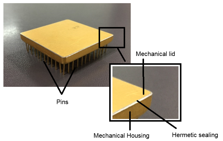 | Figure 2. Typical hybrid microcircuit package |
4. Realization
In this section, how the life of the HMC package has been estimated by calculation and testing is explained in detail. There are different methods available to estimate the fatigue life of any structure. Following equation is used for calculating the fundamental frequency. 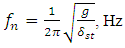 | (1) |
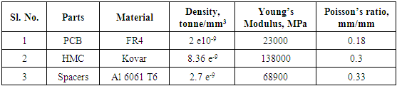
In the equation, ‘g’ is the acceleration due to gravity in mm. sec-2 and δst is the displacement of the leads in mm [10].In the current work, the fundamental frequency and peak acceleration level on the HMC package is identified using numerical code - Finite Element Method and the values are directly considered for HMC package life calculation. The HMC package (46.48mm x 33.78mm x 4.57mm) is mounted on the PCB having thickness of 1.6mm by soldering the leads. The HMC package has 34 numbers of leads with 0.45 diameters. The package mass 24 grams and PCB mass 47.56 grams has been considered for simulation.
4.1. Finite Element Analysis
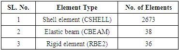
The finite element modeling of HMC package along with PCB is done using 2D shell elements and HMC leads by 1D elastic beam elements refer Figure 3. The PCB is fixed at four mounting location along with four number of aluminum spacers of 30mm length. The Eigen value analysis and Sine response analysis has been carried out. The first fundamental frequency is found to be 180Hz refer Figure 4.Table 4.1. Finite Element model details
 |
| |
|
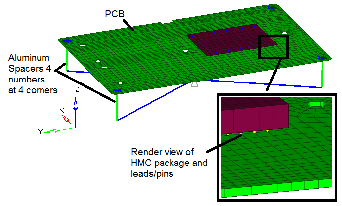 | Figure 3. Finite Element model of package along with PCB and aluminum spacers |
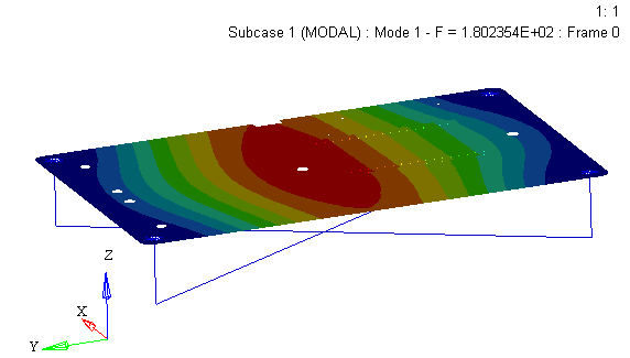 | Figure 4. First fundamental frequency observed at 180Hz |
Table 4.2. Material Specification
 |
| |
|
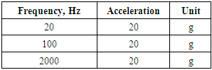
The sine response analysis has been performed for a constant 20g loading which is applied continuously in the frequency range of 20Hz to 2000 Hz. The response is extracted exactly at the center of the HMC package refer Figure 5. The peak acceleration observed on the HMC package is 244g and which is considered for package life estimation refer Figure 6.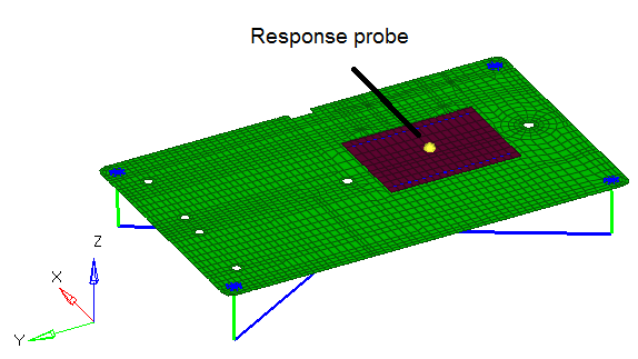 | Figure 5. Probe on HMC package for response extraction |
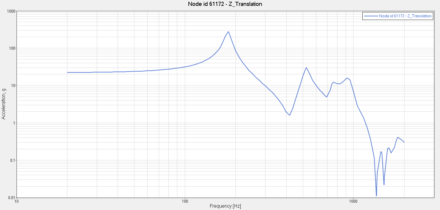 | Figure 6. Peak acceleration of 244g is observed at 180Hz |
4.2. Fatigue Life Estimation
Fatigue is a process of progressive permanent change occurring in any objects which are subjected to fluctuating stress and strains at some point and they may culminate in crack and leads to complete fracture after a sufficient number of fluctuation. The basics factors for this fatigue failure are considered to be, the maximum tensile stress of sufficiently high value, the large amount of fluctuation in the applied stress or strain and the sufficient large number of cycles of applied stress or strains.The Fatigue life of the HMC package is calculated using the following equation,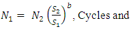 | (2) |
 | (3) |
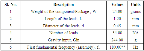
Where N1 is the cycles to failure, N2 being the cycles to failure for the respective material (taken from SN curve), S2 ultimate tensile stress in N.mm-2 of package material (from SN Curve), S1 being the bending stress from calculation and b is the fatigue exponent slope.The main parameters required for the fatigue life calculation under dynamic load condition are as follows,a. Transmissibility/ Quality factor, Qb. Stress concentration factor, Kc. Fatigue exponent slope, bd. Dynamic force, Pde. Dynamic bending stress, Sbf. Length of the leads, Lg. Radius of the leads, ch. MOI of the total numbers of leads, M andi. Fundamental frequency of the package, fn.The details of the HMC is as shown in the below Table 4.3Table 4.3. HMC package details
 |
| |
|
The dynamic force Pd acting on the HMC package is obtained from the peak acceleration observed on the package for the applied acceleration load of 20g, mass of the package refer Table 4.3 and the transmissibility ‘Q’ at the first fundamental frequency.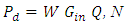 | (4) |
And, for beam type of element, the good approximation of the transmissibility value will arrive at 0.1 times the square root of the natural frequency [4, 11], since the package will be mounted on the PCB with raised height of 1.2mm and can be derived as follows, | (5) |
The dynamic bending stress Sb is again an another important parameter depends on dynamic bending moment M, radius of the HMC leads ‘c’ and the moment of inertia from 34 number of leads.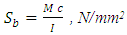 | (6) |
Where, 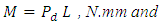 | (7) |
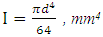 | (8) |
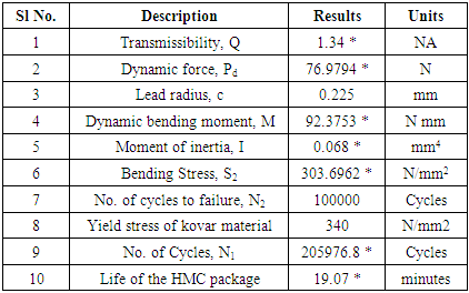
The life is calculated against the yield stress and number of cycles to failure, which is extracted from SN curve of the KOVAR material. The yield stress at 105 cycles and fatigue exponent slope at stress concentration factor K =2 is considered for calculation.By taking all these parameter into consideration, the life of HMC leads is found to be 19 minutes for a constant quasi static load 20g. The calculated values are tabulated in the Table 4.4.Table 4.4. Calculation details
 |
| |
|
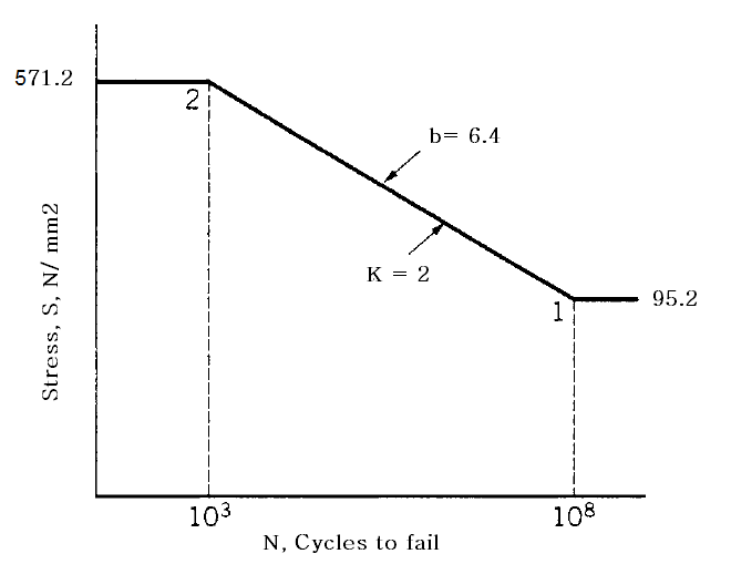 | Figure 7. SN curve of KOVAR material |
4.3. Testing
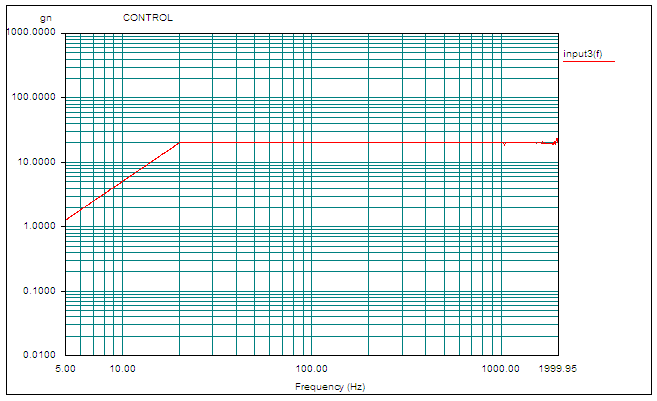
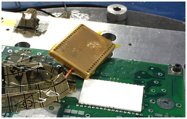
The HMC package along with PCB is fixed to shaker armature with the help of fixture/interface plate using four number of aluminum spacers (30mm x OD 10mm x ID 3.5mm) refer Figure 10.Before performing the actual vibration test, the fixture has been qualified with low level sine vibration test for 0.5 g load and a flat response has been observed through the frequency range, 20Hz to 2000Hz [12] refer Figure 9.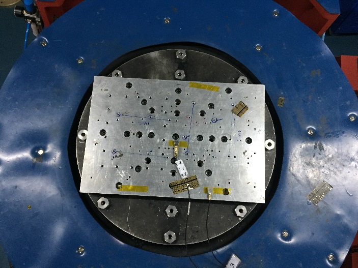 | Figure 8. Fixture resonance check test setup |
* refers to value evaluated from calculation** refers to value obtained from FEA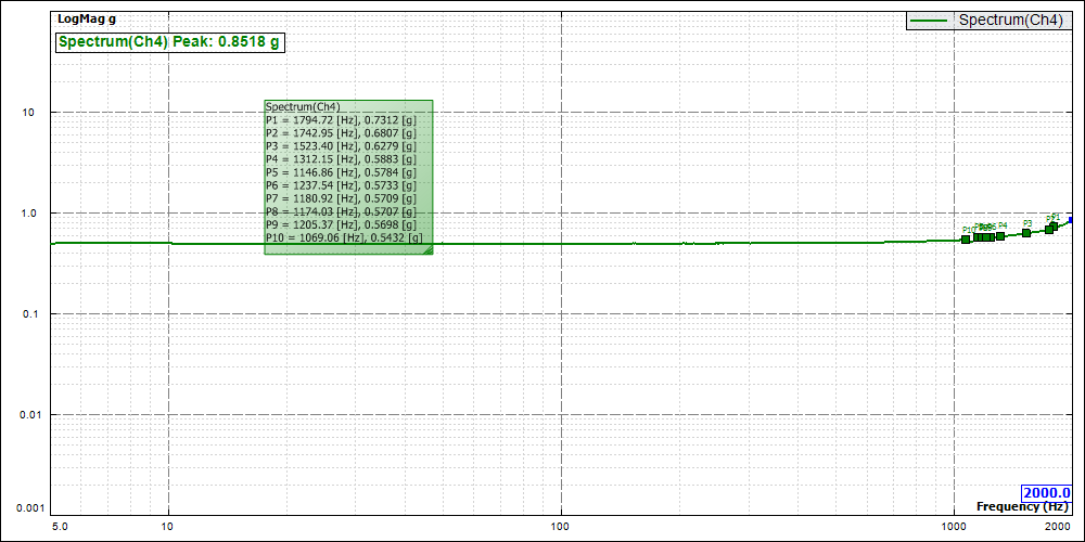 | Figure 9. Fixture resonance check plot |
The sine vibration test has been performed for the load shown in the Table 4.5, the load is applied continuously in positive and negative sweeps. The response is extracted on the HMC package to observe the dynamic behavior of the package refer Figure 10. Table 4.5. Sine response input
 |
| |
|
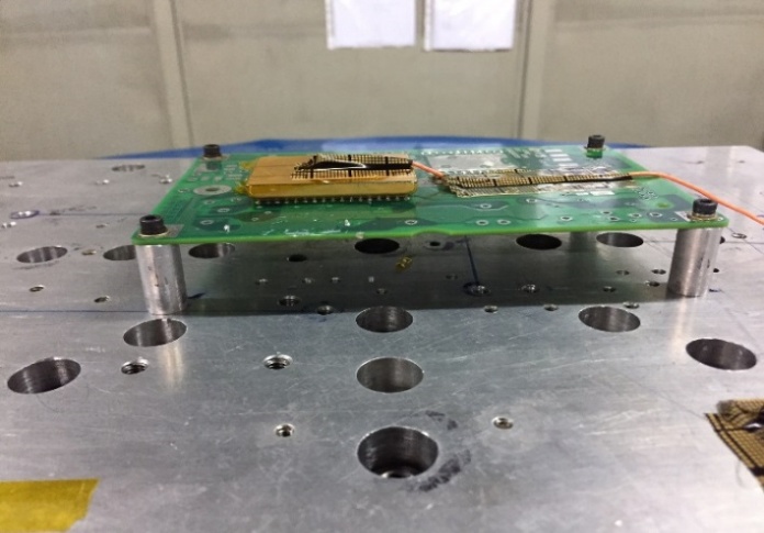 | Figure 10. Vibration test setup |
 | Figure 11. Sine response input plot |
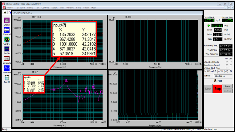 | Figure 12. Screenshot of vibration test at the package corner leads damage |
During the 4th sweep of testing at 17.34 minutes refer Figure 13, the changed vibration noise and visual inspection confirms the damage in the package corners leads refer Figure 14.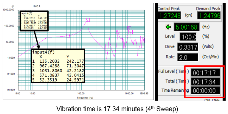 | Figure 13. Response on the package at corner leads damage |
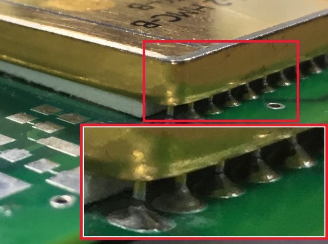 | Figure 14. Package corner leads damage |
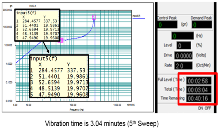
The response plot during 5th sweep of the testing at around 20.38 minutes (17.34 minutes + 3.04 minutes) shows complete drop in the dynamic response on the package refer Figure-16 which confirms the complete detachment of package leads and the package gets separates from the PCB refer Figure 17. 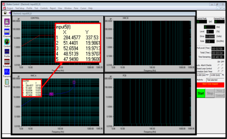 | Figure 15. Screenshot of vibration test at complete package breakdown |
 | Figure 16. Response on the package at complete package breakdown |
 | Figure 17. Package breakdown |
5. Conclusions
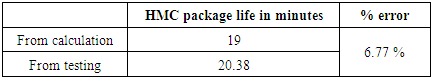
The life of the HMC package under dynamic load condition is obtained based on the results of FEA and testing is tabulated in the Table 5.1Table 5.1. HMC package fatigue life
 |
| |
|
The above table depicts the HMC package which is made up of KOVAR material with 34 number of pins which can withstand for a time of about 18 minutes when it is continuously subjected to 20g load.Also from the above table it is observed that the life of HMC package obtained from the analytical calculation and physical testing are in good correlation and hence the assumption made and fatigue parameters considered for the calculation holds good.The inference from the response plots obtained from the testing predicts the peak at first fundamental frequency and also as the sweep continues the pins experience a constant load and resulting in permanent failure which we call it as fatigue failure. From this study one can understand the serviceability of leaded components (in this case HMC) in terms of time duration can be calculated under different gravitational load. Understanding the component serviceability is very important in Aerospace and Space domain for better reliability of the products.
References
| [1] | Jerry E Sergent & Charles A Harper “Hybrid Microelectronics handbook” second edition, Mc graw hill publications. |
| [2] | F. R. Muccino “Simplified method of Hybrid microcircuit Fabrication” Jonson Hopkins applied physics laboratory. |
| [3] | Da Yu, Abdullah Al Yafawi, Seungbae Park & Soonwan Chung “Finite Element based Fatigue Life prediction for Electronic Components under Random Vibration Loading” Electronic components and Technology Conference proceedings 2010. |
| [4] | Steinberg D. S “Vibration analysis for Electronic Equipment” A Wiley-Inter science Publications. |
| [5] | Steinberg D. S “Preventing Thermal Cycling and Vibration Failures in Electronic Equipment” Wiley (New York, 2001). |
| [6] | Thomson W. T & Dahleh M. D “Theory of Vibration with Applications” Pearson Publication, Fifth Edition. |
| [7] | Ablestik, ABLEFILM 5020K technical data sheet. |
| [8] | Christopher Henderson “Hybrid Microcircuit Packaging” Part 1, Semitracks monthly newsletter. |
| [9] | Carpenter data sheet for kovar material. |
| [10] | Young W. C & Budynas R. G “Roark’s formulas for Stress and strain” McGraw-Hill Publishers, eighth edition, New Delhi. |
| [11] | Steinberg D. S “Vibration analysis for Electronic Equipment” A Wiley-Inter science Publications. |
| [12] | Santosh Joteppa & Vinod S Chippalkatti “Design and Qualification of Hybrid Micro Circuit Packages for Higher Vibration Loads for Aerospace and Defense Application” Scientific & Academic publications. |

 Abstract
 Reference
 Full-Text PDF
 Full-text HTML