Prashanth Pai M.1, Akhil Raj MP2, Manjunath B.2, Sufiyan Shaikh2, Navajasharif Gaded2
1Assistant Professor, Department of Mechanical Engineering, P.A. College of Engineering, Mangaluru, India
2UG Students, Department of Mechanical Engineering, P.A. College of Engineering, Mangaluru, India
Correspondence to: Prashanth Pai M., Assistant Professor, Department of Mechanical Engineering, P.A. College of Engineering, Mangaluru, India.
| Email: |  |
Copyright © 2017 Scientific & Academic Publishing. All Rights Reserved.
This work is licensed under the Creative Commons Attribution International License (CC BY).
http://creativecommons.org/licenses/by/4.0/

Abstract
Maintenance is one of the major requirements in automobiles for achieving their specified life span. It includes replacing punctured tyres, which always has been a difficult task. Every automotive manufacturer provides tools such as L-wrench and jack, but still, using these tools requires practice. Often, the car is provided with tyre wheel nuts remover and jack for instant spare tyre replacement. Many passenger cars, SUV and heavy vehicle accessory manufacturers concentrate on producing wheel nut puller using a single tool to loosen the nut one by one. The main problem they are facing is time consumption and tediousness of work. Therefore, it is crucial to have a tool that should be designed ergonomically, easy to handle, lightweight, requires small space, robust in nature and can perform a similar task in short time. This work is aimed at the design and analysis of wheel nut removing tool for tightening and removing of four nuts in one stroke. Due to difficulty in applying torque to remove nut and to save time, a tool having a planetary gear mechanism has been developed. In this work, focus is on the minimization of human effort for of nuts of 100mm PCD wheel at a time. The main objective of work is to develop a single tool, which can be used during assembling and disassembling of wheels in automobiles. It can be successfully used as standard tool irrespective of the model of the vehicle. Also, it can be used in garages, workshops and service stations.
Keywords:
Planetary gear mechanism, PCD, Assembling, Maintenance
Cite this paper: Prashanth Pai M., Akhil Raj MP, Manjunath B., Sufiyan Shaikh, Navajasharif Gaded, Modeling & Analysis of a Multi-Nut Operating Tool Using Catia & Ansys, Journal of Mechanical Engineering and Automation, Vol. 7 No. 5, 2017, pp. 139-144. doi: 10.5923/j.jmea.20170705.03.
1. Introduction
The common problem associated with a four-wheeler is replacing the punctured tyre with the spare tyre. This job is relatively difficult for women and the elderly drivers as the torque required to remove the wheel nuts is quite high. The nuts should be retightened after successful replacement of the punctured tyre. If the required torque is not applied in tightening the nuts, the nuts will lose, and this will affect the driver’s safety. Normally every car is provided with the tyre replacement tools such as L-shaped nut remover and jack supplied by the manufacturer. The tool used to remove the wheel nuts should be ergonomically designed, easy to handle and must consume a small space for storage. It should also be able to tighten the wheel nuts. This work is carried out to design a multi nut operating tool whose main objective is to reduce the labour work in tightening or loosening the nuts one by one. It also focuses on the minimization of human effort and time consumed for fixing all four nuts of the four-wheeler tyre with a single stroke of lever by using multiple operated spanners. This is achieved by developing a planetary gear mechanism.Mukhtar [1] designed and fabricated a 4 in 1 motorized tyre nut puller for a car tyre with 100mm pitch circle diameter. This tool can dismantle four nuts simultaneously and power up by a car battery. With assistance in CAD, CAM, CNC and Rapid prototyping, concurrent reduction of time in part assembly and optimum time in finished product was obtained. Several recommendations were given by the author to improve this product in respect of use of polymer material for creating the product casing. The bracket holder diameter size should be made in adjustable type that can be used in various types of cars that have different PCD and have a stopper to stop the movement of the gear.Rahman [2] developed nut removal with 114mm pitch circle diameter to replace T-nut wrench that can reduce the force and torque needed to open the nuts simultaneously. This tool can open four nuts in one time and the force of utilization has been reduced. This tool used mild steel as the main material to fabricate a gearing system and the gear ratio was 21.125. Bhanage [3] designed 5 in 1 nut remover with Pitch Circle Diameter (PCD) 114.3 mm for 080M40 material for gear and pinion. For validation, finite element simulation was performed for better optimized results. After meeting the design to the required standards, the fabrication of the tool was done. The results of the tests proved that the wheel nut remover could efficiently remove all the nuts simultaneously. Time required for nut removal effectively reduced up to 50% for pneumatic gun and up to 70% for L wrench.Kress [4] included the components such as multiple individual socket assemblies, universal drive gear and planet gears, Housing, Pneumatic wrench. It was observed that universal gear had driven surface allowing to be driven to remove lug nuts and pneumatic system for securing the lug nut. The tool has the potential for greatly reducing the time needed for a tyre change. Boston [5] included the components such as multiple sockets, central gear, a lug gear, outer ring gear, pneumatic system, dolly and a jack system. It was observed that outer ring gear used provides inward pressure to maintain the connection between the teeth of the lug gear and central gear.Shirley [6] included the components such as central housing, radially directed housing legs and output shaft. The bevel gears were used along with the housing legs. This setup also showed some effectiveness in construction. Palatnick [7] included the components such as nut receiving socket, stabilizing sockets. The tool includes selectively positioned non-rotating stabilizing sockets positioned to engage other nuts while one is being loosen.In the present work, CATIA software is used for the design of multi nut operating tool and the analysis is carried out using ANSYS workbench. The design is based on standard Pitch Circle Diameter of 100mm which is available in most of the car tyres. The assembly model which is created in CATIA is imported to ANSYS. The load condition and material properties are applied to the imported model, meshing is done and is then solved to obtain the results. The results are studied to check the compatibility of the design. Equivalent (Von Misses) stress, Equivalent elastic strain and Normal stress have been obtained after the analysis. In this work, the design and analysis using the two softwares has been restricted only for gears as they are the core components of the multi nut operating tool.
2. Gear Design
Multi-nut operating tool (Figure 1) is invented to reduce the effort and time in replacing the wheels of the vehicles. The plurality of lug nuts can be removed at one time without the usage of an electric motor or any hydraulic and pneumatic devices. The planetary shafts are arranged exactly in the pitch circle position of the lug nuts. This method can be used to remove any number of lug nuts but the design of gear varies according to the certain parameters like number of lug nuts, pitch circle diameter.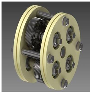 | Figure 1. Multi-nut operating tool |
The fundamentals of law of gearing have to be followed in designing the spur gears. The Fundamental law of gearing states that, “For a pair of gear to transmit constant angular velocity ratio, the tooth profiles of these mating gears must be designed in such a way that the common normal (line n-n) or the line of action passes through a fixed point, or also known as the pitch point, on the line of centres.
2.1. Gear Design Calculations
For Sun Gear, Outer Diameter, dg = 60mm and Number of Teeth, Zg = 26.For Planetary Gear, Outer Diameter = 50mm and Number of Teeth, Zp = 21.The above values are chosen based on PCD of 100mm, which was used for most of the vehicles having four-wheel nuts.The Torque required to rotate the central shaft is obtained from related studies and this torque is then further transmitted to other shafts.An approximate Human force is assumed and applied to the handle to rotate the central shaft.Torque required to rotate central shaft = 120NmAverage force which has to be applied on the handle by a person = 500NLength of handle = 500mm; Pressure angle = 20°From the design data hand book [8] we have,Gear Ratio = Zg/Zp = 26/21 = 1.23Module, m = dg/ Zg = 60/26 = 2.3mmFace width, b = 9.5m < b < 12.5m = 25mm.
2.2. Material Properties
For gears, normally EN8 is the material used, which is an unalloyed medium carbon steel grade with reasonable tensile strength. It is widely used for applications which require better properties than mild steel, but does not justify the costs of an alloy steel.Ultimate tensile strength, Su = 550 N/mm2Yield strength, Sy = 280 N/mm2Young’s Modulus, E = 200000 N/mm2Poisson’s Ratio, µ = 0.3Brinell Hardness = 255BHNPermissible bending stress is same for both gear and pinion as the material used is same. Now, for both gear and pinion,σb = Su/3 = 550/3 = 183.33 N/mm2.
2.3. Beam Strength and Effective Load
The beam strength, Fb of both gear and pinion is given by, | (1) |
where, module, m = 2.3mm, face width, b = 25mm.Permissible bending stress, σb = 183.33 N/mm2.The beam strength, Fb = 3162.4 N.When same material is used for pinion and gear, pinion is weaker than the gear during bending; hence it is necessary to find out Effective load, Feff for calculating Factor of Safety.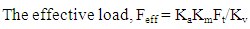 | (2) |
where, Ka = Overload Factor, Km = Load distribution factor, Kv = Velocity Factor and Ft = Driving or Tangential load.For moderate shock and precise gearing, Ka = 1.25, for face width up to 50 mm, Km = 1.2 and for fine hobbing process, V = 22 m/s.Torque required for removal of 4 nuts is 480 NmIf a pneumatic motor is selected of 200 rpm, N = 200rpm. | (3) |
P = 10.051 kWTangential force, Ft = P/V = 10.051 × 10³/22 = 456.87 N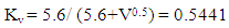 | (4) |
Hence, Effective load, Feff = KaKmFt/Kv = 1259.52N | (5) |
FOS = 3162.4/1259.52 = 2.51> 1.5As the available FOS of gear pair is higher than that of required factor of safety, the design of gear pair is safe.
3. Modeling
3.1. Three Dimensional Modeling of Multi Nut Operating Tool Using CATIA V5R21
Part is created in part design work bench. The path is: Start > Mechanical design > part design. Graphical User Interface of part design workbench is opened. Next step is to create a 3D model of the part with available dimensions. First step of a 3D model is to draw the 2D cross sectional profile of the part in sketcher workbench in the software. Part drawn in the sketcher workbench is then converted into a 3D model by using 3D tools. The 3D models of the components such as gear, shaft, ball bearing and the casing are shown in the figures 2,3,4, and 5 (a), 5 (b) respectively.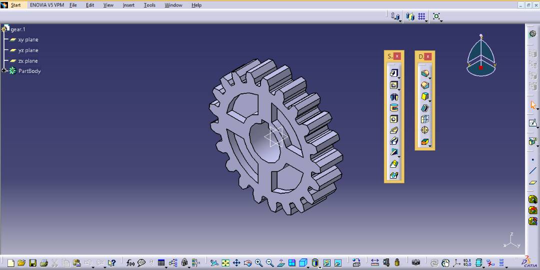 | Figure 2. 3D model of the gear |
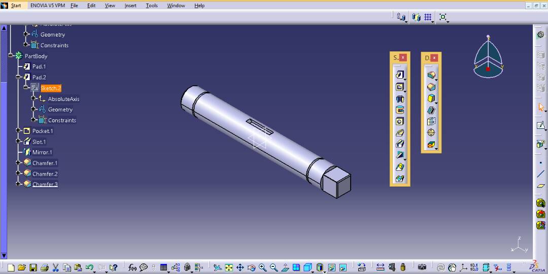 | Figure 3. 3D model of the shaft |
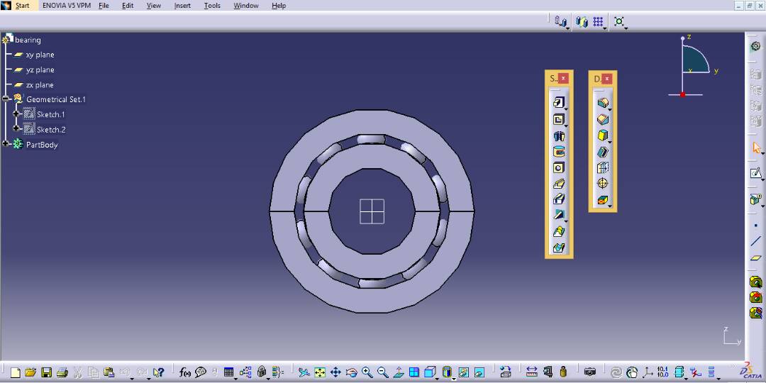 | Figure 4. 3D model of the ball bearing |
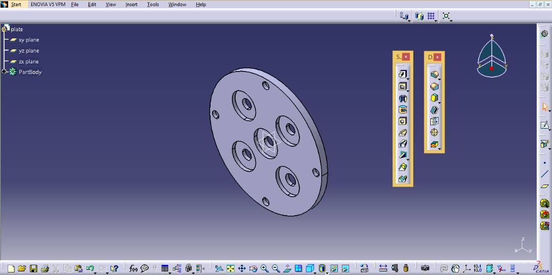 | Figure 5(a). 3D model of the casing |
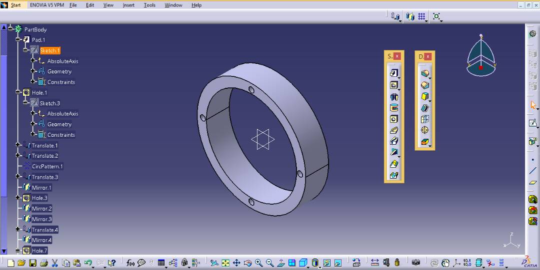 | Figure 5(b). 3D model of the casing |
3.2. Assembly of Multi Nut Operating Tool Components
After completing 3D modeling of the components, one needs to go to the assembly work bench. Path is: Start < mechanical design < assembly design. The complete assembled body of the multi nut operating tool is shown in the figure 6 and exploded views are in from figure 7 and 8.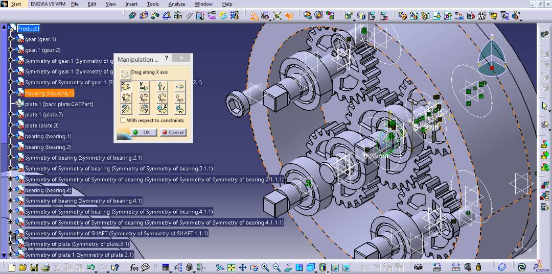 | Figure 6. Assembled model of multi nut operating tool |
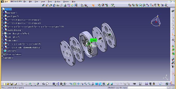 | Figure 7. Exploded view of the model |
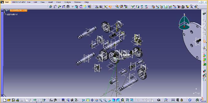 | Figure 8. Exploded view of the model |
4. Results
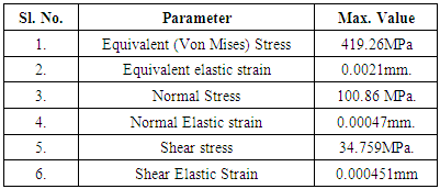
The results of the analysis are generated in the form of stress variation images. The highly stressed or deformed regions in a part are shown by red colored area and the corresponding values are indicated as per the color variation scale. Figures 9 to 16 show the results of the static structural analysis using ANSYS Workbench. Figure 10 shows the boundary conditions those are applied for the model. The bearings are given the fixed condition and the torque of 120 Nm is given to the central shaft. Figure 11 indicates that the maximum Equivalent (Von Mises) Stress value is 419.26MPa. Figure 12 indicates that the maximum Equivalent elastic strain value is 0.0021mm. Figure 13 indicates that the maximum value of the normal stress is 100.86 MPa.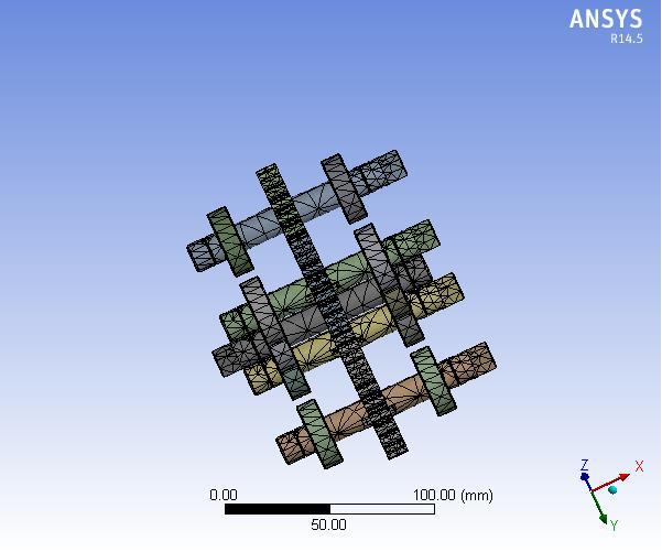 | Figure 9. Meshed diagram of the model |
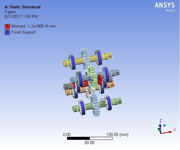 | Figure 10. Boundary conditions |
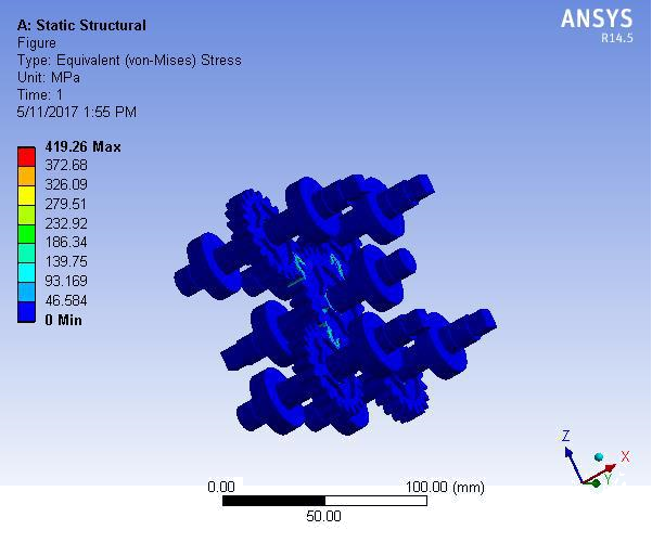 | Figure 11. Equivalent (Von Mises) Stress |
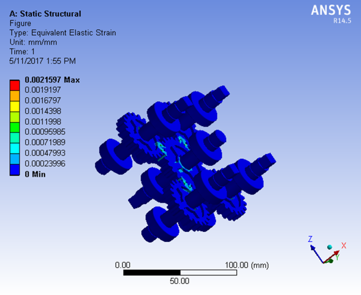 | Figure 12. Equivalent elastic strain |
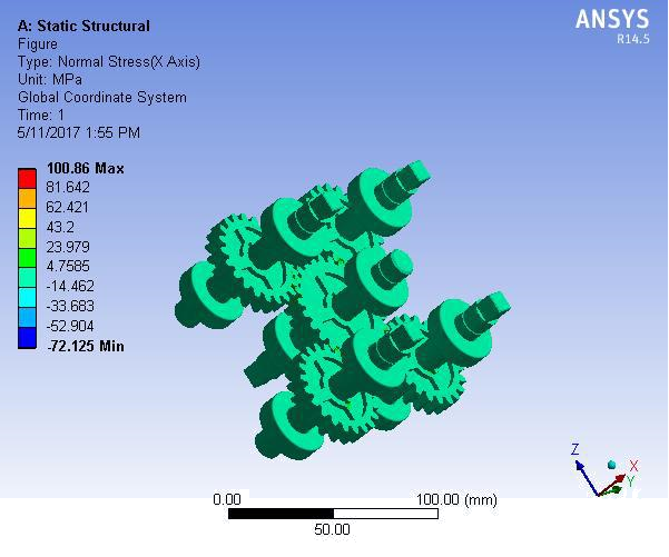 | Figure 13. Normal Stress (X Axis) |
Figure 14 shows that the maximum value of the Normal Elastic strain (X Axis) is 0.00047mm. Figures 15 and 16 show that the maximum value of shear stress and shear strain are 34.759MPa and 0.000451mm respectively. The results are tabulated in table 1.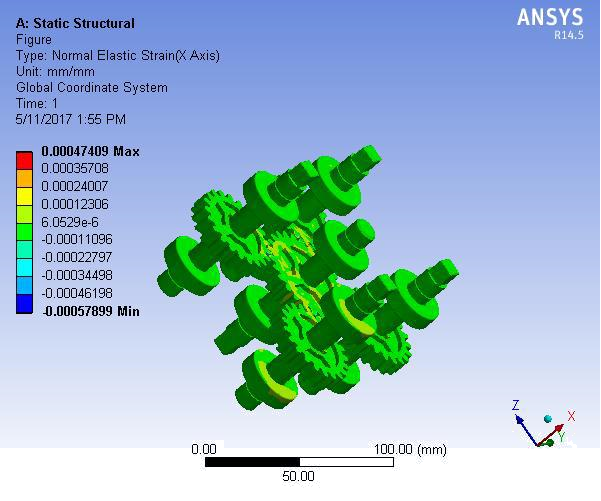 | Figure 14. Normal Elastic strain (X Axis) |
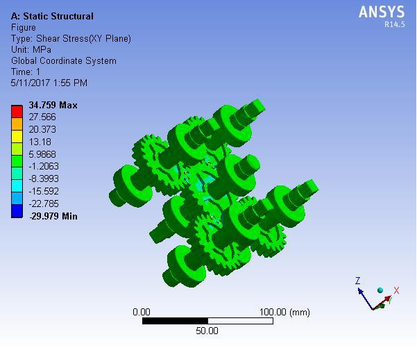 | Figure 15. Shear stress (XY Plane) |
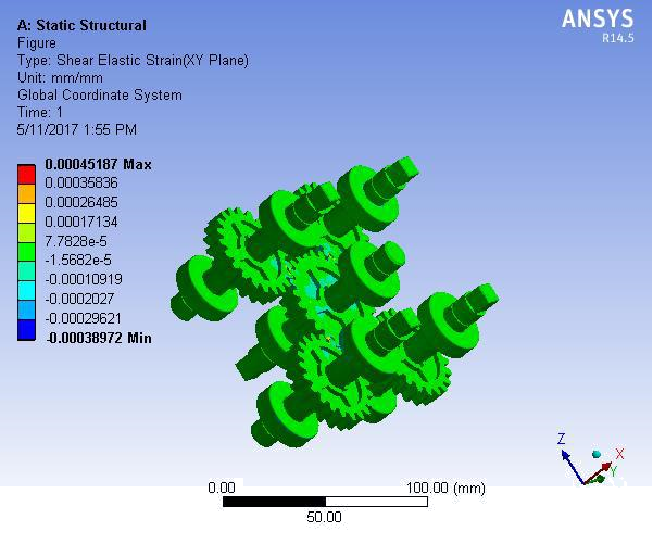 | Figure 16. Shear Elastic Strain (XY Plane) |
Table 1. Tabulation of results
 |
| |
|
5. Conclusions
In this work, the design and analysis of multi nut operating tool is done by using advanced softwares such as CATIA and ANSYS. The analysed results are very close to the theoretical values and the design of gears is found to be safe. For better optimized results finite element simulation can be performed. As the design is safe, product assembly may be manufactured and tested.
References
| [1] | M. Mukhtar, M.H.P Hilmie Hussaine, 2014, Design Improvement and Computer Assisted Fabrication on the Impact Wrench for a Car Wheel Nuts Puller in Automotive Industry, Australian Journal of Basic and Applied Science, Vol.1, Issue 3, ISSN: 2320-401X, pp. 381-384. |
| [2] | Azizul Rahman B Abd Aziz, 2008, Improvement and Optimization of Tyre Nut Remover with 114 PCD”. University of Malaysia, Pahang. |
| [3] | Amol Bhanage, Suraj Bedse, Keval Devare, Varsharani Batte, Komal Dixit, 2015, Design and Development of All Wheel Nut Remover for Automotive, International Journal of Applied Engineering Research, ISSN: 0973-4562, Volume 10, No.7, pp. 17631-17641. |
| [4] | Joseph M. Kress, 2001, Multi lug nut removal tool, US publication No. US6305245B1. |
| [5] | Larry Boston, 2003, Multi-lug socket tool, US publication No. US6668685B2. |
| [6] | David B. Shirley, 1991, Lug nut tool, US publication No. US 5074170A. |
| [7] | Leonard Palatnick, 1975, Lug nut remover, US publication No. US3905254A. |
| [8] | K. Mahadevan and K. Balaveera Reddy, 2013, Design Data Handbook for Mechanical Engineering in SI and Metric units, Fourth Edition, CBS Publications and Distributors Pvt. Ltd., New Delhi. |

 Abstract
 Reference
 Full-Text PDF
 Full-text HTML