Sudheer Kini K.1, Sudarshan M. L.2, Ajith K.2, Shreepathi K.2, Santosh Wodeyar N. S.3
1Department of Mechanical Engineering, St Joseph Engineering College, Mangaluru, India
2Department of Mechanical Engineering, Vivekananda College of Engineering and Technology, Puttur, India
3Department of Mechanical Engineering, APS College of Engineering, Bengaluru, India
Correspondence to: Sudheer Kini K., Department of Mechanical Engineering, St Joseph Engineering College, Mangaluru, India.
| Email: |  |
Copyright © 2017 Scientific & Academic Publishing. All Rights Reserved.
This work is licensed under the Creative Commons Attribution International License (CC BY).
http://creativecommons.org/licenses/by/4.0/

Abstract
Agriculture plays a vital role in the overall growth of the country. Over 60% population of the country depend on the country depend on the agriculture. These people will face different variety of problems from the beginning of cropping till the stage of cultivation. Out of these the transportation is also a type, either to carry the pesticides to the cropland or to take back the cultivated crop. The present work involved the design and fabrication of a universal power cart. It can be used to handle the agricultural product and goods. It is desired to carry up to 250kgs of load. Details of a simple, study and efficient power cart, financially beneficial, are given here. Safety aspects are incorporated. The problem of handling, moving and operating is simpler and it finds huge applications. Power drive saves time and thus increases the overall productivity.
Keywords:
Agriculture, Transportation, Universal power cart
Cite this paper: Sudheer Kini K., Sudarshan M. L., Ajith K., Shreepathi K., Santosh Wodeyar N. S., Design and Fabrication of Universal Power Cart, Journal of Mechanical Engineering and Automation, Vol. 7 No. 5, 2017, pp. 135-138. doi: 10.5923/j.jmea.20170705.02.
1. Introduction
A cart is a vehicle designed for transport, using wheels and normally pulled by one or a pair of draught animals. A handcart is pulled or pushed by one or more people. Hydrocarbon combustion has a major impact on the global environment because it is responsible for 80% of the green house gas emissions, which are the principal cause of climate warming and air pollution [1]. It is different from a dray or wagon, which is a heavy transport vehicle with four wheels, which in turn is different from a carriage, which is used exclusively for transporting humans. The restriction of "carts" to two wheels has become less strictly observed since they were commonly horse-drawn, particularly for those pushed by people [2]. Many three-wheelers which exist in the form of motorcycle-based machines are often called trikes and often have the front single wheel and mechanics similar to that of a motorcycle and the rear axle similar to that of a car.We have many methods to transport the goods from one location to another. Human’s first means of transport were using human muscle-power. Later in the middle of 19th century the gasoline powered cart were used .Today most of the farmers use traditional method of transporting goods using muscle power and only a few are using either non powered cart or the gasoline powered cart. Need for the improvement of the present system is the lack of sufficient manpower. This necessitates the use of appropriate machinery to aid in transportation of goods. During the last few decades, environmental impact of the petroleum-based transportation infrastructure, along with the peak oil, has led to renewed interest in an electric transportation infrastructure. Based on this realization we are planning to make the cart that is driven by electricity [3, 4, 8].
2. Machine Description
The Universal Power Cart is a electric drive vehicle, uses a DC motor that is directly powered from a external power station. The motor and battery are housed in the vehicle casing. Power transmission is done using chain drive and gear trains. The single front wheel is used to give direction and the power is transmitted to the two rear wheels. The rear wheel is with a differential assembly. A vehicle's wheels rotate at different speeds, mainly when turning corners. The differential is designed to drive a pair of wheels while allowing them to rotate at different speeds. There is an option of disengaging the gears when the driving power is not used. The main parts of the power cart are DC motor, battery, chain drives, chassis, front and rear wheels, differential unit and electric connections.
3. Design Considerations
3.1. General
The major parts involved in the universal power cart and the design aspects which ensure the safety features. The main components that play a very important role in design and fabrication of universal power cart are1. Rollover Stability 2. Drive system3. Power transmission4. Carrier5. Steering component6. Drum brake
3.1.1. Rollover Stability
A conventional, non-tilting three wheel cart can equal the rollover resistance of a four wheel car, provided the location of the center-of-gravity (cg) is low and near the side-by-side wheels. Like a four wheel vehicle, a three-wheeler's margin of safety against rollover is determined by its L/H ratio, or the half-tread (L) in relation to the cg height (H). Unlike a four-wheeler, however, a three-wheeler's half-tread is determined by the relationship between the actual tread (distance between the side-by-side wheels) and the longitudinal location of the cg, which translates into an "effective" half-tread. The effective half-tread can be increased by placing the side-by-side wheels farther apart, by locating the cg closer to the side-by-side wheels, and to a lesser degree by increasing the wheelbase. Rollover resistance increases when the effective half-tread is increased and when the cg is lowered, both of which increase the L/H ratio.
3.1.2. Drive System
A DC motor is an electric motor that runs on direct current (DC) electricity. A permanent-magnet motor does not have a field winding on the stator frame, instead relying on permanent magnets to provide the magnetic field against which the rotor field interacts to produce torque. Compensating windings in series with the armature may be used on large motors to improve commutation under load. Because this field is fixed, it cannot be adjusted for speed control. Permanent-magnet fields (stators) are convenient in miniature motors to eliminate the power consumption of the field winding. Battery is the chief power supplier of universal power cart. Two Lead-acid batteries with 12V, 100 Ah output are housed in the chassis, but only one battery is used at a time for driving the cart. Electric connections are made. The two way switch is used to give forward and reverse directions.
3.1.3. Power Transmission
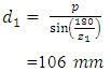
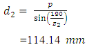
Chain is used to transmit power from the gear box output to the shaft. It is often used to convey power to wheels. Chain drive passes over a sprocket gear, with the teeth of gear meshing with the holes in the links of the chain. We have used chain drive of type 208A with standard pitch of 25.40 mm with chain length 845mm and 21 links. Gear is used to transmit torque. In the fabrication we have used two spur gears; each with 32 number of teethes. It is mainly used to transmit the power to the differential system in rear wheel. The option of disengaging the gear is also provided. By disengaging the gears, the power transmission from DC motor to the differential system can be interrupted and vehicle can be moved by applying the muscular power.Sprocket is a profiled wheel with teeth that mesh with a chain drive. The name sprocket applies generally to any wheel upon which radial projections that engage a chain passing over it. We have used two sprocket wheels of diameter 106mm and 114mm with 13 and 14 numbers of teethes respectively.
3.1.4. Carrier
Carrier is the most essential part of universal power cart, as it is suppose to carry a large volume of contents while travelling. It need to flexible towards loading and unloading of goods and should be lighter. It has length 110cm, width 90cm and height 25 cm.
3.1.5. Steering Component
The single front wheel is used to serve the purpose of giving direction to the universal power cart vehicle. The load falling on this front wheel should be as low as possible. For this purpose the front wheel is fitted to the chassis with an angle of 30°.Two important components of steering mechanism in universal power cart are, handle which is connected to the front wheel assembly through a lever and differential.
3.1.6. Drum Brake
A drum brake is a brake in which the friction is caused by a set of shoes or pads that press against a rotating drum shaped part called brake drum. When the brakes are applied, the cam shaft rotates, which will make the shoe or pad to come in contact with tire disc. The frictional force will tend to stop the tire from rotating.
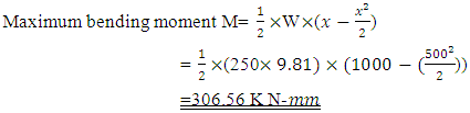
4. Design Calculations
For the effective working of any machine, the parts need a systematic design to withstand any drastic conditions. The universal power cart unit holds the following systems,1. Drive system2. Steering mechanism3. Carrier
4.1. DC Motor & Power Requirement
To calculate the horsepower of a motor when current, efficiency and voltage are assumed,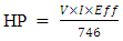 | (1) |
Where, HP- Horsepower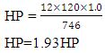 For proper and effective working of universal power cart, the 2HP DC motor is selected. The power supply is done using external battery with output voltage of 12V.
4.1.1. Design of Shaft
According to Maximum normal stress theory,Speed of the shaft =30 RPM, Power to be transmitted =1.498 KW, Load =250 kg (approximate), Yield stress (C40) 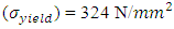 For solid shaft K=0
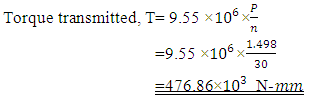 | (2) |
 | (3) |
Assume steady load or gradually applied loads, for which  and
and  Diameter of the shaft,
 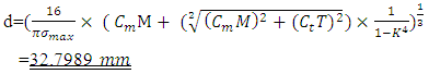 | (4) |
According to maximum shear stress theory,Diameter,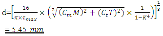 | (5) |
Thus from (4) and (5), we conclude that for a safe design the minimum diameter of shaft is d=32.7985 mm.
4.1.2. Power Transmitter
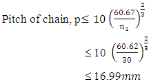
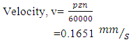
Type of chain drive used- roller chain drive.Power to be transmitted =1.498 KWCenter distance, C=307.5 mmNumber of teeth on sprockets,  Speed of sprocket,
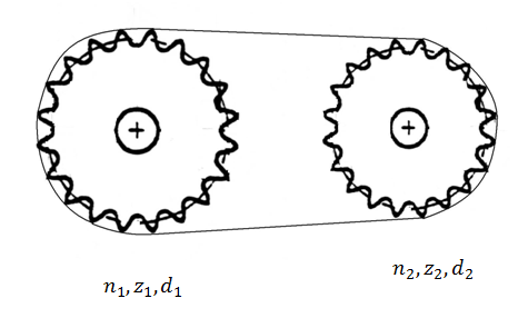 | Figure 1. Roller chain passing over a pair of sprocket |
 | (6) |
From the design data hand book, standard pitch,  Select the chain number 208AMeasuring load =127.50 NBreaking load
  Pitch diameter
 | (7) |
 | (8) |
 | (9) |
Centre distance, 

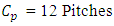
 | (10) |
The chain length pitches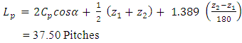 | (11) |
Chain length,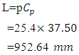 | (12) |
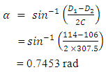
The maximum steering angle is the angle of the wheel centre plane with maximum left and right steering wheel angle with respect to the vehicle longitudinal centre plane.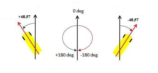 | Figure 2. Steering angle |
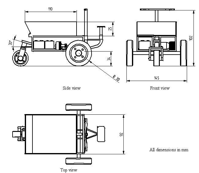
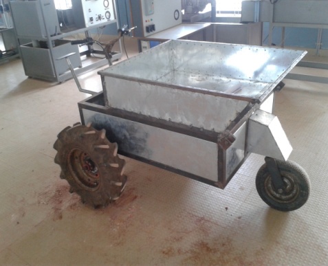
A 3-Dimensional drawing, Orthographic views of universal power cart with all the system of parts is shown in Figure 3 and Figure 4. A final fabricated model is shown in Figure 5.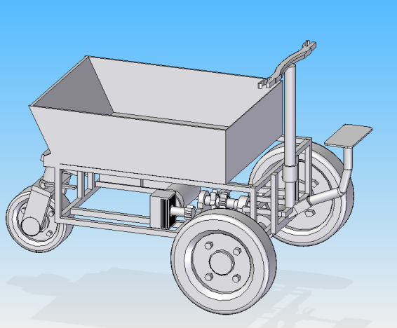 | Figure 3. A 3 dimensional view of universal power cart |
 | Figure 4. Orthographic views of Universal power cart |
 | Figure 5. A Fabricated model |
5. Conclusions
In this modern world the time and cost has more weightage for each and operation. So in accordance to this concept we have designed and fabricated the vehicle named “Universal Power Cart” to reduce cost and to save human energy. By viewing many types of carts like non powered traditional carts, gasoline powered cart and other, we conclude that the electric driven system is efficient, economical and require less maintenance. Machine can be operated efficiently even by untrained person and it does not require lengthy training for operating and the machine can be understood easily. The vehicle can be used for transportation of various types of goods. Compared to traditional gasoline carts this cart is economical and eco-friendly. Quite obviously quietness and green are two objectives that seem to be driving the auto scene at the moment.
References
| [1] | Fe´lix Barreras, “Design and development of a multipurpose utility AWD electric vehicle with a hybrid powertrain based on PEM fuel cells and batteries,” International journal of hydrogen energy, vol. 37, pp. 15367-15379, 2012. |
| [2] | EIA. International energy outlook 2000. Washington: Energy Information Administration, US Department of Energy; 2000. |
| [3] | Cardinali L, Santomassimo S, Stefanoni M. Design and realization of a 300 W fuel cell generator on an electric bicycle. J Power Sources 2002; 106: 384e7. |
| [4] | Hwang JJ, Wang DY, Shih NC, Lai DY, Chen CK. Development of fuel cell powered electric bicycle. J Power Sources 2004; 133: 223e8. |
| [5] | V.K Chandegara “Design and developing of bullock drawn multi‐purpose implement for sandy loam soil”, Journal of agricultural engineering, Vol, 40(4): October December, 2003. |
| [6] | Design of Machine Elements, V.B. Bhandari, Tata McGraw Hill, 2nd Ed. |
| [7] | Data Hand Book, K. Mahadevana and Balaveera Reddy, CBS Publication. |
| [8] | Beneito R, Vilaplana J, Gisbert S. Electric toy vehicle powered by a PEMFC stack. Int J Hydrogen Energy 2007; 32:1554e8. |
| [9] | Khurmi, R.S. and Gupta, J.K.. A Textbook of Machine Design (S.I. Units), Eurasia publishing House (PVT) Ltd., Ram Nagar, New Delhi-11005s, 2005. |

 Abstract
 Reference
 Full-Text PDF
 Full-text HTML