-
Paper Information
- Next Paper
- Previous Paper
- Paper Submission
-
Journal Information
- About This Journal
- Editorial Board
- Current Issue
- Archive
- Author Guidelines
- Contact Us
Journal of Mechanical Engineering and Automation
p-ISSN: 2163-2405 e-ISSN: 2163-2413
2017; 7(4): 116-118
doi:10.5923/j.jmea.20170704.06

Design and Fabrication of Magnetic Braking System
James Valder, Vishwas Naik, Zarnab Ahmed, Vishwajit Ghorpade, Daniyel Ahmed
Department of Mechanical Engineering, St Joseph Engineering College, Mangaluru, India
Correspondence to: James Valder, Department of Mechanical Engineering, St Joseph Engineering College, Mangaluru, India.
| Email: |  |
Copyright © 2017 Scientific & Academic Publishing. All Rights Reserved.
This work is licensed under the Creative Commons Attribution International License (CC BY).
http://creativecommons.org/licenses/by/4.0/

The conventional brake system depends on the principle of friction for operation. The braking system is one of the most important safety systems in a vehicle. The ability of the braking system is to bring the vehicle to the safe controlled stop. It is absolutely essential in preventing accidental vehicle damage, personal injury and loss of life. This study deals with the concept and design of a magnetic braking system used in small and medium vehicles. In the present work one such attempt is made by using magnetic field as a braking system.
Keywords: Magnetic field, Neodymium magnets, Magnetic repulsion, Brake
Cite this paper: James Valder, Vishwas Naik, Zarnab Ahmed, Vishwajit Ghorpade, Daniyel Ahmed, Design and Fabrication of Magnetic Braking System, Journal of Mechanical Engineering and Automation, Vol. 7 No. 4, 2017, pp. 116-118. doi: 10.5923/j.jmea.20170704.06.
Article Outline
1. Introduction
- The brake system is one of the most important safety systems on a vehicle. The ability of the brake system is to bring the vehicle to the safe controlled stop is absolutely essential in preventing accidental vehicle damage, personal injury, and loss of life [1]. The conventional brake system depends on the principle of friction for operation. Sliding friction (kinetic friction) is the rubbing action of one object sliding on the surface of another, such as a brake disk on a brake pad or a brake drum on a brake lining. The components of the conventional brake system such as pad, drum, lining etc. become worn out over time. Therefore, the components of the conventional brake system must be replaced periodically. In addition, friction produces heat, which must be dissipated by the brake drum and linings or rotor and pad. Heat caused by repeated severe braking and wears causes brake fade. So to overcome these permanent neodymium magnets are used. [2-4]. These magnets having high magnetic repulsion and attraction force helps in braking effect [5]. These are totally friction less. Due to this, they are more durable & have longer life span. These brakes are an excellent replacement over the conventional brakes due to their many advantages. Magnetic brake doesn’t require any interfacing relay. Due to its non-grease bearings, the pins of magnetic brake do not require any friction buster. So this can be implemented in the lighter vehicles and work handling devices to reduce wear in brakes.
2. Principle of Working
2.1. Parts Involved
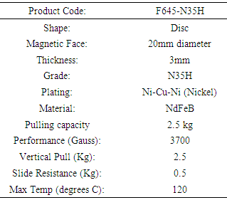
- • Magnetic rotor and stator • Shaft • Bearings • Neodymium magnets • Fasteners • Spring • Brake lever and cable • Wheel• DC motor • BatteryFigure 1 shows the model of a fabricated nylon material rotor and stator (frame). A shaft is a rotating machine element, usually circular in cross section, which is used to transmit power from one part to another. A bearing is a machine element that constrains relative motion to only the desired motion, and reduces friction between moving parts. A fastener is a hardware device that mechanically joins or affixes two or more objects together. A spring is an elastic object used to store mechanical energy. Springs are usually made out of steel. Brake levers are the small metal levers mounted on the handle bars that, when pulled, actuate the brakes (by means of either pulling a cable or compressing hydraulic fluid) to bring the vehicle to a halt. A wheel is a circular component that is intended to rotate on an axle bearing. Neodymium magnets are shown in Figure 2.
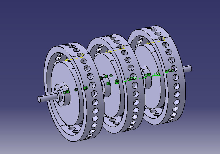 | Figure 1. Schematic representation of the model of a fabricated nylon material rotor and stator (frame) |
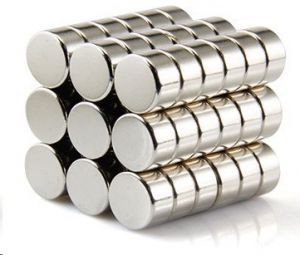 | Figure 2. Neodymium magnets [6] |
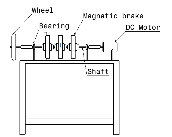 | Figure 3. Schematic representation of magnetic braking system |
|
2.2. Working
- The repelling of magnetic forces is used to stop the wheel or to bring the rotor at the rest. In present setup the motion of the wheel occurs due to supply of power from battery to the motor as an axillary driving system. This wheel is brought into rest or neutral with the help of a magnetic rotor and casing, where permanent magnets are placed. When brake lever is operated brake cable pulls the free end of the casing (frame). When this casing comes closer to the magnetic repulsion force gets locked by the magnetic field of other repulsion of permanent magnet and thus when the magnetic flux passes through and perpendicular to the rotating rotor the flux developed by the magnets on the frame opposes the rotating wheel/rotor direction [2]. This results in the rotating wheel or rotor comes to rest/ neutral. Figure 4 shows the magnetic braking system setup.
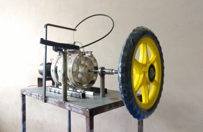 | Figure 4. Magnetic braking system |
3. Conclusions
- A magnetic brake for lighter automobiles and human handling devices such as stretchers and wheel chairs has an effective braking system. In addition, by using these magnetic brakes the life of the braking unit can be increased.This magnetic braking system is found to be more reliable as compared to other braking systems.
 Abstract
 Reference
 Full-Text PDF
 Full-text HTML