Manjunath B. A., Binu K. G., Santhosh H., Rahul Kumar
Department of Mechanical Engineering, SJEC, Mangaluru, India
Correspondence to: Santhosh H., Department of Mechanical Engineering, SJEC, Mangaluru, India.
| Email: |  |
Copyright © 2017 Scientific & Academic Publishing. All Rights Reserved.
This work is licensed under the Creative Commons Attribution International License (CC BY).
http://creativecommons.org/licenses/by/4.0/

Abstract
The rate depletion of conventional sources of energy are much faster than the new ones are made, which puts us in place to consider and identify the other sources of energy to drive the needs of the world. Compressed air as the energy source has shown promising results in the field of automobile. Efforts are being made by many organizations to design and develop compressed air-driven vehicle which definitely going to reduce the uses of fossil fuels and its share in the environment. This study presents the methodology towards design and fabrication of an Air-Driven vehicle equipped with pneumatic power generating concept. Performance test was conducted at different valve opening position to find the optimum rate of compressed air inlet to the engine. The result of the performance test revealed that out of three different valve conditions, the optimum power generated and transmitted by the engine took place at full open valve condition and the time taken to reach 10 meters distance for the full open valve is lesser in comparison with the 3/4th and half open valve. The estimated cost of the machine is Rupees Twenty Eight Thousand approximately.
Keywords:
Design, Air driven vehicle, Pneumatic system
Cite this paper: Manjunath B. A., Binu K. G., Santhosh H., Rahul Kumar, Design and Fabrication of Air Driven Vehicle, Journal of Mechanical Engineering and Automation, Vol. 7 No. 4, 2017, pp. 112-115. doi: 10.5923/j.jmea.20170704.05.
1. Introduction
The exhaust emission standards are getting more and more stringent and there now exists a discussion about the introduction of a mandatory emissions standard for CO2, a greenhouse gas that contributes to the climate change which is an issue of growing international concern. This demand for lower exhaust emission levels together with increasing fuel prices leads to the demand of combustion engines with better fuel economy, which forces engine developers to find and investigate more efficient alternative engine management. Gasoline is already the fuel of the past. Automobile manufacturers know all of this and have spent lots of time and money to find and develop the fuel of the future. An air powered engine is a type of motor which does mechanical work by expanding compressed air. Pneumatic motors generally convert the compressed air energy to mechanical work through either linear or rotary motion. Linear motion can come from either a diaphragm or piston actuator, while rotary motion is supplied by either a vane type air motor, piston air motor, air turbine or gear type motor. Compressing a gas into a small space is a way to store energy. When the gas expands again, that energy is released to do work. The cars that increase in numbers every day emit toxic emissions on our highways and consume huge amount of fossil fuels, but oil and gas reserves will last until 2042. Consequently, unconventional energy sources must be increasingly harnessed. Because of the low efficiency of CAEs, they were not used for a long time. Piston-type CAEs have been commonly used in high-power machines that require a high-starting torque [1]. The compressed air storage tanks built with carbon fibers will carry high amount of pressure with minimum volume space which obviously meets the requirement with the conventional engines with zero emission [2]. Using the two-stage pneumatic on/off valves for gas exchange could simplify the structure of APE because they need not have the traditional engine valves and valve springs [3]. Force and moment originating in the assembly components also influence the physical behavior of pneumatic actuators. As a consequence the assembly components force and moment considerably influence the speed of the pneumatic actuator and hereby also the duration of the assembly process [4]. Compared to batteries, compressed air is favorable because of a high energy density, low toxicity, fast filling at low cost and long service life. It has zero emission and is ideal for city driving condition [5]. The four stroke vehicle that runs with the assistance of compressed air can succeed a 50km/h speed and refilling of compressed air to the tank is for 70-80 km. [6].
2. Working Principle
Connections are done as per the circuit diagram as shown in figure 1. When the accelerator pedal is pressed, air is passed through the solenoid valve from the reservoir to the cylinder. Now the piston inside the cylinder is pushed forward. When it attains maximum position, the reed switch sensor which is connected along the cylinder changes the direction of flow of air. Hence, the piston is pushed backward. Thus the forward and backward movement of the piston is connected to the crank shaft. Hence linear movement of the piston is converted into a rotary motion by means of chain and sprocket which is connected with the rear axle. Thus the vehicle attains its motion.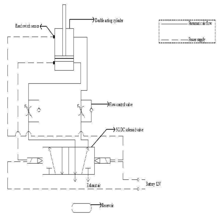 | Figure 1. Pneumatic Circuit |
3. Design Analysis
3.1. Structural Analysis of Vehicle Frame
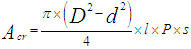
Considering the vehicle base frame, analysis is conducted to determine the load bearing capacity of the frame at various points and its behavior when subjected to bending loads. Pulling force is calculated using the equation (1).
3.2. Pulling Force Calculation for Piston
 | (1) |
Where, D1 = Bore Diameter = 63mm, D2 = Piston Rod Diameter = 20mm.
3.3. Cylinder Thrust
The Thrust developed in the cylinder that is the piston power is a function of piston diameter, operating air pressure and the frictional resistance. Cylinder thrust can be calculated by using the formula (2). | (2) |
For double acting cylinder, Piston Diameter d=63 mm, Pa = 0.6 MPa. The cylinder thrust developed will be 1870.4 N.
3.4. Air Consumption by Pneumatic Cylinder
It is the amount of air required to actuate the pneumatic cylinder. Considering cylinder specifications and various parameters such as pressure, stroke, stroke length, etc it is substituted in equation 4.4 and values are obtained to determine the size of reservoir in litters.Bore Diameter, D=63mm, Rod Diameter, d= 20mmPressure, P = 6bar, Stroke, S = 127 strokes/minStroke length, L =6 cm. Air consumption by cylinder in forward and reverse stroke is calculated using the formula (3) and (4) respectively. | (3) |
 | (4) |
Air consumption by cylinder in forward and reverse stroke is 142.52 liters/min and 128.15 liters/min. Total air consumption is 270.67 liters/min.
3.5. Power Calculations
The speed for full, 3/4th and half open of the valve is noted by connecting a tachometer to the wheel is 535, 420 and 395 rpm. The diameter of the wheel, d=300 mm, the velocity for various speed is calculated by the equation (5). | (5) |
Velocity of full, 3/4th and half open valve is 8.4, 6.6 and 6.2 m/s. The time taken to reach the top speed is 5sec and acceleration is 1.24 m/s2. Mass of the vehicle is 90kg. Force required for moving the vehicle is 111.6 N.
3.6. Rolling Resistance
Rolling resistance, sometimes called rolling friction or rolling drag, is the force resisting the motion when a body rolls on a surface. The rolling resistance of the wheel is calculated using the equation (6) and coefficient of friction is 0.015. | (6) |
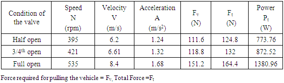
The rolling resistance of the wheel is 13.24N. The total force is 124.84 N. The total power output is calculated using the formula (7) and power output is 773.76N, 872.52N and 1380.96N for different valve condition.  | (7) |
3.7. Force Calculations
3.7.1. Tractive Force, FT
Traction is the force used to generate motion between a body and a tangential surface, through the use of dry friction. The traction force required to overcome by the wheels is 111.6N.
3.7.2. Force Required on Incline
Assuming incline angle, θ=10° and weight of the vehicle, W=882.9N. Force required on incline is calculated using the formula (8) and Fg is found to be 153.3N | (8) |
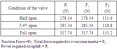
Total force required to overcome inertia is found out using the equation (9) and Fi is found to be 278.14N,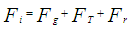 | (9) |
3.8. Power Required for Uphill Climb
Velocity is 1m/s for uphill climb [2] and power required is calculated using the equation (10). | (10) |
Power required for uphill climb is 278.14W.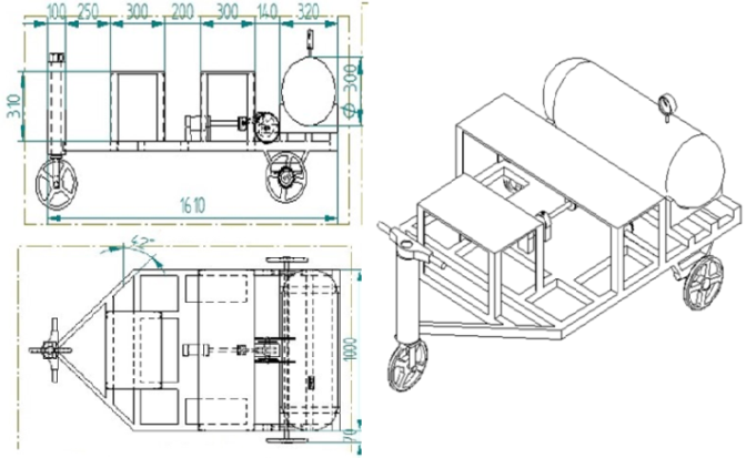 | Figure 2. Side view, top view and isometric view of air driven vehicle |
4. Performance Test and Evaluation
4.1. Performance Evaluation Procedure
A Compressed-air engine is a pneumatic actuator that does work by expanding compressed air which is stored in the tank. An air driven vehicle is powered by an air engine, using compressed air, which is stored in a tank as shown in figure 3. Compressed air vehicles (CAV) use the expansion of compressed air to drive their pistons.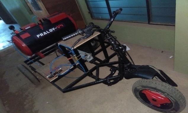 | Figure 3. Prototype of air driven vehicle |
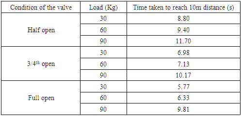
The engine is runned by considering the various valve conditions. The three different valve conditions is full open, 3/4th open and half open. By connecting tachometer to the wheel, speed of the engine for the three different valves is calculated. Table 1 gives the details of speed, velocity, acceleration, force required to pull the vehicle, total force and power for the full open, 3/4th open and half open valve condition. Traction force and power required on uphill climb is given in the table 2. Time taken to reach a distance of 10m is tested by applying three different loads of 30, 60 and 90 kg for the full open, 3/4th open and half open valve conditions is shown in table 3.Table 1. Power Calculation of the model
 |
| |
|
Table 2. Tractive force calculation of the model
 |
| |
|
Table 3. Result of performance evaluation of air driven vehicle
 |
| |
|
4.2. Results
The speed of the air driven vehicle increased from half open valve to full open valve condition. The corresponding total force and power were plotted with respect to speed. As speed increases total force and power of the air driven vehicle also increases respectively as shown in figure 4. It is observed that the power is greater in the full open valve when compared to the 3/4th open and half open valve.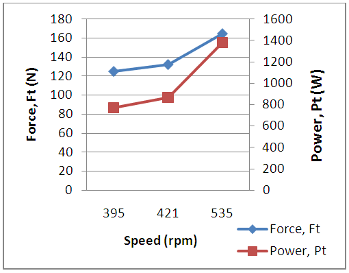 | Figure 4. Speed Vs Force, Power plot for valve opening |
The performance evaluation of the air driven vehicle is evaluated for the three different loads at three different valve conditions. From figure 5 it noted that as load increased in the air driven vehicle time taken to reach 10m distance also increases. It is observed that the time taken to reach 10m distance when the valve is half open is lesser in comparison to the valve is full open. When the valve is 3/4th open time taken to reach 10m distance will be lesser as compared with the full open valve and higher with the half open valve.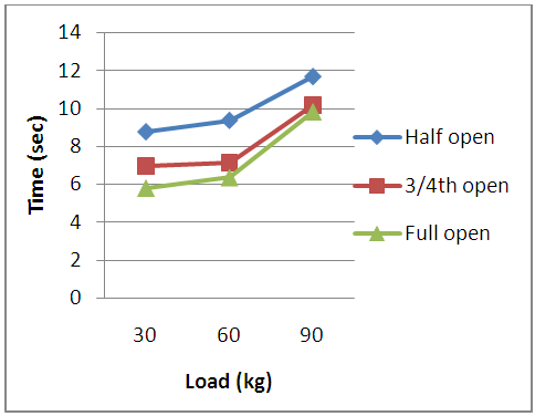 | Figure 5. Load Vs Time plot for valve opening |
5. Conclusions
The air driven vehicle is designed and developed which runs with the help of compressed air as the fuel. The pneumatic three wheeler reduces the environmental pollution and is beneficial for handicapped people and old age people for easy transportation. The vehicle is operated in three different valve conditions. The result of the performance test revealed that out of three different valve conditions, the optimum power generated and transmitted by the engine took place at full open valve condition and the time taken to reach 10 meters distance for the full open valve is lesser in comparison with the 3/4th and half open valve.
ACKNOWLEDGEMENTS
The authors are very grateful to the Principal, SJEC Mangaluru, for guiding this work and providing lab faciliteis and workshop.
References
| [1] | YU Qihui, CAI Maolin, SHI Yan, XU Qiyue, “Optimization Study on a Single-cylinder Compressed Air Engine” Vol. 28, No. 6, May 20, 2015. |
| [2] | Venkatesh Boddapati, S.V.V. Vinod, M. Dora Babu, “Air Powered Vehicle -An Eco Friendly Engine,” Volume 4, No. 1, January 2015. |
| [3] | Ping-lu CHEN, Xiao-li YU, Lin LIU, “Simulation and experimental study of electro-pneumatic valve used in air-powered engine,” Vol. 10(3), Dec. 29, 2008, pp: 377-383. |
| [4] | Dennis Effmert., “Simulation of the Pneumatic Behavior in the Virtual Commissioning of Automated Assembly Systems”, Springer International Publishing Switzerland, DOI: 10.1007/978-3-319-00557-7_17, 2013. |
| [5] | S. S. Verma, “Latest Developments of a Compressed Air Vehicle: A Status Report,” Vol. 13, Issue 1, Version 1.0, 2013. |
| [6] | Mistry Manish K., Pravin P. Rathod., Sorathiya Arvind S., “Study and development of compressed air engine single cylinder: A review study,” IJAET, Vol. 3 Issue 1, January-March, 2012, pp: 271-274. |

 Abstract
 Reference
 Full-Text PDF
 Full-text HTML