-
Paper Information
- Next Paper
- Paper Submission
-
Journal Information
- About This Journal
- Editorial Board
- Current Issue
- Archive
- Author Guidelines
- Contact Us
Journal of Mechanical Engineering and Automation
p-ISSN: 2163-2405 e-ISSN: 2163-2413
2017; 7(3): 72-76
doi:10.5923/j.jmea.20170703.02

A Study on Mechanical and Vibration Characteristics of Mother of Pearl Filled Fibre Reinforced Epoxy Composite
 Abstract
 Reference
 Full-Text PDF
 Full-text HTML
Rakshit A.1, Mahesh B. Davanageri1, Hanuamntharaya R.1, Babishsha K. C.1, Deeksha Shetty A.2
1Department of Mechanical Engineering, Sahyadri College of Engineering and Management, Adyar, Mangalore, India
2Department of Civil Engineering, Sahyadri College of Engineering and Management, Adyar, Mangalore, India
Correspondence to: Mahesh B. Davanageri, Department of Mechanical Engineering, Sahyadri College of Engineering and Management, Adyar, Mangalore, India.
| Email: |  |
Copyright © 2017 Scientific & Academic Publishing. All Rights Reserved.
This work is licensed under the Creative Commons Attribution International License (CC BY).
http://creativecommons.org/licenses/by/4.0/

The present work aimed to determine the mechanical and vibration characteristics of Glass/Epoxy composite with Mother of Pearl as secondary reinforcing material (filler material). The secondary material percentage was varied for three different compositions i.e., for composite with 5%, 10% and 15% weight percentage of filler material. The results showed that the Composite reinforced with 5% filler material yielded better results for Tension, whereas the composite reinforced with 15% filler material gave better results for Flexural and Vibration tests. The Experimental results were further verified by Analytical method using Nastran Software. The Experimental and Analytical results showed agreement with each other.
Keywords: Hand layup, FFT analyser, Tensile and Flexural property, Vibration Characteristic
Cite this paper: Rakshit A., Mahesh B. Davanageri, Hanuamntharaya R., Babishsha K. C., Deeksha Shetty A., A Study on Mechanical and Vibration Characteristics of Mother of Pearl Filled Fibre Reinforced Epoxy Composite, Journal of Mechanical Engineering and Automation, Vol. 7 No. 3, 2017, pp. 72-76. doi: 10.5923/j.jmea.20170703.02.
Article Outline
1. Introduction
- Composite is a material composed of two or more materials embedded in it. The composites can further be characterised as Polymer Matrix Composite, Metal Matrix Composite and Ceramic Matrix Composite. Composites are made of Reinforcement and Matrix. The composition of the material mainly depends upon the application of the material and Polymer Matrix Composite find immense use in the field of Engineering like Aerospace, Automobile and due to higher ratio of strength to weight, lesser densities, lower coefficient of Thermal Expansion, good resistance to corrosion, low strain and better thermal resistance.Authors have studied the effect of orientation of glass fibres in glass epoxy composite. The composite was prepared by hand layup process and the results showed good behaviour for ±45º oriented fibres [1]. Amit Kumar et.al worked on Glass Epoxy Composite to study its mechanical properties. The fibres used were unidirectional and bidirectional and the results showed better agreement for unidirectional fibre composites [2]. Bakir et.al investigated effect of Fibre orientation on Mechanical properties in Glass Epoxy composite and the results were found to be good for ±45º oriented fibres [3]. Michael et.al studied the mechanical properties of Periwinkle shell composite with CNSL resin prepared by compression mould technique. The effect of filler material size and volume % composition was also studied and optimum results were obtained with size of 400µ in accordance with 30% volume of Filler material [4]. Abiodum et.al worked on composite made of unsaturated polyester which used sea shell powder as filler material with size of 250µ. The filler material was varied for various % combinations. The results obtained were better for composite with 10% of filler material [5].Gajendra et.al worked on Bio Composites composed of sea shell. The sea shell powder was varied in % and had a size of 75µ. The Tribological properties for the same were studied by conducting pin on disc test. The results proved that there was decrease in wear as of sea shell powder increased [6]. Karthick et.al studied mechanical properties of in % from 2%-20%. The results obtained were better for 12% composition compared to other compositions [7]. Manohara et.al worked on composite made of Sea shell with Jute fabric. The sea shell powder % was varied in composition and the composite with 5% of sea shell yielded better results [8]. S.S. Chavan et.al worked on E-Glass Composite to study its Vibration Characteristics and how Number of layers and aspect ratio of the material affects it. Modal Analysis Technique was used for experimental study and Ansys software was used for analytical study. The results showed that as there was increase in Number of layers and aspect ratio the Natural Frequency also increased [9]. Similar work was carried out by Sharaya et.al and the effect of Fibre orientation was studied [10]. Seth S. Kessler et.al worked on Composite material to predict damage by Frequency response method. The study was conducted on various damaged specimens and studying the responses for the same. The Experiment showed good results at lower frequencies than at higher frequencies [11]. Caleb et.al worked on Composite to detect damage in the part by Frequency Response Method. Two different boundary conditions were employed for the study that is free-free and fixed-fixed. Both undamaged and damaged specimens were used for the study purpose and tests showed lower frequencies for damaged specimen [12]. Zou et.al worked on composite structures to detect and monitor delamination in composites due to Vibrations experienced. Modal analysis technique was employed for the study and these results were compared with results obtained from FEM approach. The delamination resulted in increase in damping which reduced frequencies and this was justified by experimental results [13]. Several works were conducted on Composite with Sea shell powder as filler material but none of them highlight the vibration characteristics of the same. The present study was done in order to know the mechanical properties.
2. Experimentation
2.1. Material
- In the present work E-Glass fibre with 204gsm and 0-90º orientation was used and the matrix material used was Lapox L-12 in combination with K-6 hardener which was available commercially. The filler material used in this work was Mother of Pearl powder. The Mother of Pearl Powder was prepared from Shells obtained at sea shore followed by washing and drying and then powdering it by crushing it. The filler powder used was sieved to size of 450microns for further use.
2.2. Preparation of Specimen
- The fabrication of the composite follows Hand layup process and the specimen is prepared on the mould of dimensions
 Initially the mould is covered by thin OHP sheet or Plastic sheet with a layer of coconut oil or Vaseline on it which acts as lubricant and does not allow the material to stick to the mould. After this the Glass fibres with required dimensions are oriented on the mould properly and the epoxy with varying % of filler material and 10% of hardener is applied over it. This process is continued until the required layers are according to calculations and lastly on the top of final layer the thin OHP sheet or plastic sheet with coconut oil or Vaseline is placed and then some weight is kept in order to press the material against each other and bond properly. Further curing is accomplished for a day and then the material is exposed to sun for next 3 days. Once the material is cured and further cut into required dimensions for the tests to be done.
2.3. Test Setup and Specimen Standards
- As the present work is focused on determining the mechanical properties of fabricated composite, it was accomplished by conducting tests like Tension, Bending and also Vibration characteristics were by Vibration test conducted. The Tensile test was carried out on an Instron 3366 machine. The specimen used for the test satisfied ASTM D 638 standards [14]. The setup for the test and the specimen used are shown in 1 and 2 below.
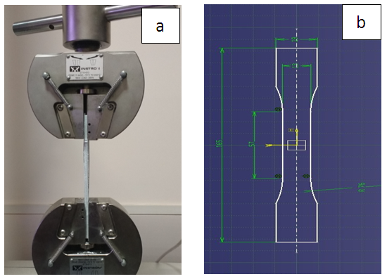 | Figure 1. a) Tensile Test Setup and b) ASTM 638 standard Tensile Specimen |
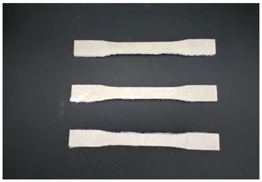 | Figure 2. Tensile Specimen |
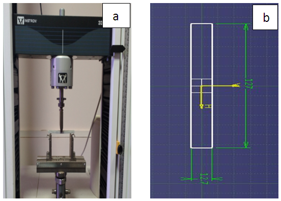 | Figure 3. a) Flexural Test Setup and b) ASTM D 790 standard Bending Specimen |
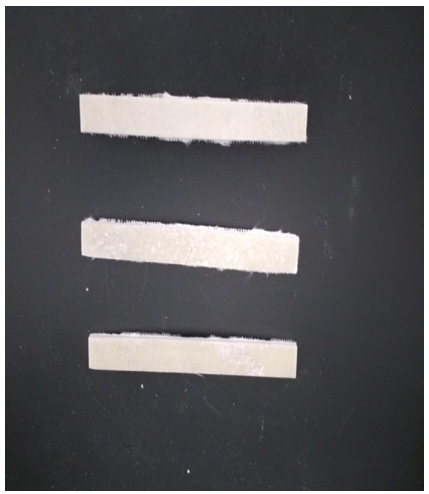 | Figure 4. Fabricated flexural specimen |
 The boundary condition for the test was cantilever support. When the specimen is supported the effective length of the specimen was 180mm [14]. The experimental setup is shown in the Figure 5.
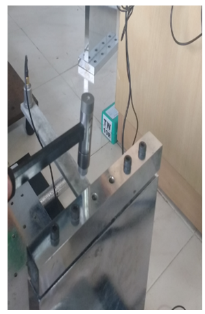 | Figure 5. Experimental Setup for vibration test |
3. Results and Discussion
3.1. Tensile Test
- For Tensile Testing Instron 3366 machine is used and the specimen which is in the shape of dumbbell is mounted between 2 arms of the Testing machine. The load is continuously applied until there is rupture in the specimen and once the specimen undergoes fracture the corresponding load is noted down to know the Ultimate Tensile Stress. The Stress Strain curve obtained from the Tensile guides to determine the Young’s Modulus of the material. The Tensile Strength of the material is mainly dependent on Strength of the fibre, length of the fibre, strength of the matrix used and filler interaction [15].The Figure 6 shows plot of Stress along Y-axis vs. Strain along X-axis. The Tensile stress for the material with 5% filer material is maximum compared to material having filler % of 10 and 15. This may be due to better adhesion of Polymer/Filler and good dispersion of particles in it [15]. The Testing results showed that the Composite with 5%, 10% and 15% of Filler Material carried a load of 10.5KN, 10.1KN and 9.82KN respectively. The Young’s Modulus achieved for 5%, 10% and 15% of Filler Material were 7.6GPa, 7.7GPa and 7.4GPa respectively. The behaviour of the specimen under tensile loading are plotted in graphs shown. The material which carried maximum load was the material with 5% of Filler material.
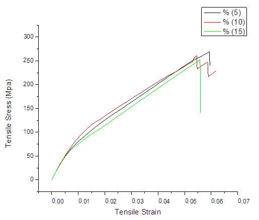 | Figure 6. Combined Tensile Test Results |
3.2. Three Point Bending Test
- The Three Point Bending test is carried out on Instron 3366 machine. The Specimen is mounted on its edges and the load acts at the centre of specimen. The specimen is loaded continuously until it undergoes fracture and the corresponding Ultimate Bending Stress value is noted down.The Figure 7 shows plot of Stress vs. Extension. It is evident from the graph that as stress in the material increases the extension also increases until the material fails. From above plots of Flexural Test we can note that the Composite with 5% Filler bears a maximum load of 304.45N, whereas the Composite with 10% Filler withstands a load of 313.14N and the composite with 15% Filler can bear a load of 322.68N. It is evident from the graph that the material with 15% filler material holds good strength to bending when compared to others and the reason for this may be due to load taking capacity of the filler material and load transferring capacity of it [15]. The Young’s modulus for the composites with 5%, 10% and 15% filler material were found to be 60.56GPa, 61.5241GPa and 59.92GPa respectively.
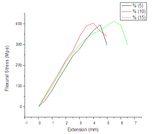 | Figure 7. Combined Flexural test results |
3.3. Vibration Test
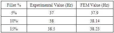
- The Vibration test was carried out in order to know the Vibration characteristics and the method used was modal analysis method. The Modal Analysis Technique was used for the experimentation [16].The Figure 8 shows the plot of Magnitude vs. Frequency for particular test. The graph shows variation in amplitude for different frequencies for Glass/Epoxy Composite with 5%, 10% and 15% of Filler material. The material with 5% of filler material has greater frequencies when compared to 10% and 15% compositions. It can be said that the material with 15% of filler material shows good behaviour for Vibration characteristics and this can be justified by knowing the logarithmic decrement. The Logarithmic decrement for the same is calculated by Numerical method with bandwidth method.
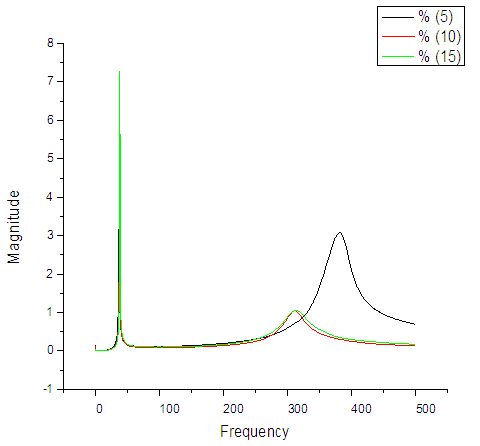 | Figure 8. Combined vibration test results |
3.4. Nastran Analysis
- The Vibration Experiment results were compared with Analytical results which were achieved by analysing each beam by Nastran software. The Mode 1 analyses for all three compositions shown in Figures 9, 10 and 11. Each composition of the material was done by utilising the properties obtained from the Tests.
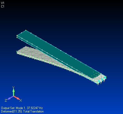 | Figure 9. Mode 1 analysis for 5% Filler material |
 | Figure 10. Mode 1 analysis for 10% Filler material |
 | Figure 11. Mode 1 analysis for 15% Filler material |
|
4. Conclusions
- The tests conducted on the Composite showed that the Filler material affected the properties of Composite Material. The Material with 5% of filler material showed better strength for Tension followed by 10% and 15% filler material which means minimum % filler material composition yields better Tensile properties. The tests were also carried out for bending and it was found that the composite with 15% Filler material gave better strengths for rupture where as 5% and 10% were comparatively low. The bending strengths were found to be optimum at 15%. The tests for Vibration gave better results for 15% which gave lower logarithmic decrement than 5% and 10% compositions. As the logarithmic decrement was found to be lower it means the material can withstand vibrations better than that of 5% and 10% composition materials.