Maria-Cristina Nițu, Claudiu-Ionel Nicola, Marcel Nicola, Marian Duță
Research, Development Division for Electric Equipment and Energy Efficiency, National Institute for Research, Development and Testing in Electrical Engineering – Icmet, Craiova, Romania
Correspondence to: Claudiu-Ionel Nicola, Research, Development Division for Electric Equipment and Energy Efficiency, National Institute for Research, Development and Testing in Electrical Engineering – Icmet, Craiova, Romania.
| Email: |  |
Copyright © 2017 Scientific & Academic Publishing. All Rights Reserved.
This work is licensed under the Creative Commons Attribution International License (CC BY).
http://creativecommons.org/licenses/by/4.0/

Abstract
The values of the current which occurs when connecting the transformer at the mains can result in electrical and mechanical stress in transformer, which in turn can lead to failures, jeopardizing the reliability of the power system, and implicitly of the power transformer. In order to avoid major failures in the power system, we developed a mathematical model in this paper in order to detect the size and time of occurrence of the transient current from the design stage. The mathematical model of the transformer was validated through tests (simulations, measurements) for the purpose of assessing the electrical stress in power transformers. The transformer on which the test was carried out is a 15 MVA, 10.5/6.3 kV transformer, the modeling of the phenomenon which occurs when connecting the transformer at the mains was achieved using the LabVIEW software, and the results obtained are consistent with the results achieved through the experimental tests carried out.
Keywords:
Inrush current, Transformer, Transient regime, LabVIEW simulation
Cite this paper: Maria-Cristina Nițu, Claudiu-Ionel Nicola, Marcel Nicola, Marian Duță, Determination of Inrush Current to High Power Transformers using the LabVIEW Environment, Journal of Mechanical Engineering and Automation, Vol. 7 No. 2, 2017, pp. 46-52. doi: 10.5923/j.jmea.20170702.03.
1. Introduction
In recent decades, the use of computers in various fields of activity has become a necessity. From the first design stages and up to the final stage (construction) of a product, the computer has replaced the classic gear. Therefore it was possible to take advantage of effective methods. Genuine virtual prototypes can be created using the computer, with a view to obtaining products which meet the functional requirements on the market. Hence the simulation of the mechanical/electrical systems is carried out until achieving a precise modeling of both system components and of its operating conditions, enabling fast testing of multiple constructive versions, for system optimization [1].Unlike other power equipment, power transformers are complex oscillating systems, which can undergo failure, for certain forms of voltage, even when the main voltage does not exceed the voltage determined through sizing.When connecting the transformer to the mains, very high currents develop in the active parts of the transformer, which exceed by much the maximum rating of the steady state current.The reliability of the power system is a matter of interest, due to the fact that the transformer manufacturer cannot provide information on their behavior when connecting and disconnecting them to/from the mains, therefore it is necessary to ensure their reliability by predetermining the size of the transient current. In order to limit the consequences of excess transient current, technical solutions are available for implementation in the power system (controlled connection of transformer phases [2-4]; fastening the protections at high levels during connection) and solutions relating to the design, ensuring an acceptable level of transient current.Inrush current is a problem, because it interferes with the operation of circuits as they have been designed to function. In a digital world, there is zero tolerance for periods of power failure.Some effects of high inrush include nuisance fuse or breaker interruptions, as well as arcing and failure of primary circuit components, such as switches. High inrush currents also require oversizing of fuses or breakers, which complicates other aspects of testing approvals and may compromise protection for other vital components. Another side effect of high inrush is the injection of noise and distortion back into the mains.Local transformer engineers currently have no custom software to highlight the electrical and/or mechanical stress in case of transitory regime. For this reason we considered developing a program to enable us to predetermine the size of the transient current occurring when connecting the power transformer to the mains [5-7].
2. Theoretical Concepts
The following is an analysis of the transient phenomena caused by connecting the transformer to the mains, leading to overloads.It is established that when the transformer running without load, the transformer primary steady state input current is low compared to the rated current, reaching 3-10% of the rated current [8]. In case of transient regime resulting from closing the circuit-breaker connecting the transformer to the mains, the current can reach up to five times the rated current value.In order to determine the inrush current, a sinusoidal voltage is applied at the terminals, such as. | (1) |
where:-  is the voltage applied to the primary at time
  -
-  the initial phase angle.The peak value and the flow of the inrush current depend on the value of the voltage applied at the time of connection (time characterized by
  ).The equation for the operation of the primary is [8]:
 | (2) |
where: -  primary resistance; -
  inrush current;-
  number of turns in the primary;-
  - the transformer no-load connection flow (fascicular flow), for simplicity we will consider that this flow passes through all the series turns of the winding and that it is located in the air gap.The equation (2) can be written as a relation between the inrush current and the flow, with reference to inductance:
 | (3) |
where:-  - total inductance, which should be considered variable within certain limits, according to the magnetic saturation of the iron. I. Determination of
  based on the magnetization curveBy identifying the coordinates of the points which correspond to the magnetization curve of the magnetic core [9] for a transformer of 15 MVA, respectively values which correspond to magnetic induction (B) on the horizontal axis and the magnetic field strength (H) on the vertical axis, we can determine the magnetization curve of the magnetic circuit,
  a) Determination of the magnetic field flux which occurs when connecting the transformer to the mains.In order to determine the magnetic field flux which occurs when connecting the transformer to the mains we use the values of the magnetic induction generated by the magnetization curve material provided by the manufacturer. The magnetic field flux values are obtained based on the following relationship (4):
 | (4) |
where  is the magnetic core column section.b) Determination of the current which occurs when connecting the transformer to the mainsIn order to determine the current which occurs when connecting the transformer to the mains we use the values of the magnetic field strength obtained from the magnetization curve.The values of the current are obtained based on the following relationship (5):
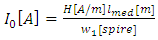 | (5) |
where: -  the average length of the magnetic field line; -
  the magnetic field strength;-
  the number of turns in the primary.where: -
  yoke length; -
  column length;-
  the number of turns in the primary.The average length of the field line is determined based on the following relationship [8]:
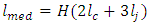 | (6) |
II. Determination of the transformer parameters- determination of the no-load current: | (7) |
where k is the ratio in percent between idle current and nominal current.- determination of the line current: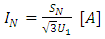 | (8) |
If the connection in the primary is YN, then the phase current is equal to the line current, and if the connection in the primary is, the current through the sides of the triangle is determined by using the following relationship (9): | (9) |
where  is the current through a phase winding.- determination of the value of the magnetic field flux
  for transformer no-load operation:
 | (10) |
- determination of the leakage reactance: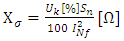 | (11) |
- determination of the leakage inductance: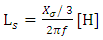 | (12) |
- determination of the leakage inductance: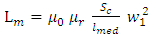 | (13) |
where:-  - absolute magnetic permeability;
 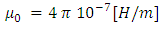 | (14) |
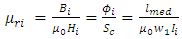
-  - relative permeability;
 | (15) |
-  - cross-section area of the magnetic core
  The size of the magnetization inductance varies in time with the variation of the magnetic field flux and the current through the transformer winding. A value of the relative permeability
  which corresponds to time
  of the transient process will result for each value of the flux
 | (16) |
For time  the transient value of
  is determined using the following relationship:
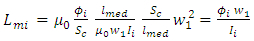 | (17) |
- determination of the core losses equivalent resistance: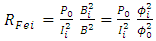 | (18) |
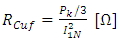
- determination of the heat losses equivalent resistance.Current  in no-load is much lower than the rated current
  No current passes through the secondary winding and therefore the heat losses (copper losses) in this winding are negligible.
 | (19) |
 | (20) |
- calculation of total resistance: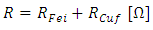 | (21) |
- calculation of total inductance: | (22) |
- calculation of winding time constant: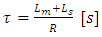 | (23) |
- calculation of peak flux value: | (24) |
If the transformer has been previously energized, at initial time  when connecting the transformer to the mains, there will be a residual flux
  in the ferromagnetic core, and the magnetic field flux variation can be determined using the following relationship [8]:The equation of the instantaneous flow is given by the relation:
 | (25) |
In the case presented in this paper we considered that the transformer has not been previously energized, therefore the residual flux will be equal to zero.The total inductance L is the sum of the leakage inductance and the magnetization inductance in the first moments of the coupling.The resistance R sums up, at the first moment of transformer coupling, the high voltage winding resistance and the resistance equivalent to iron loss.Since the transformer has not been previously connected to the mains, at time t=0 there is no residual flux in the ferromagnetic core,  It has been established that the most favorable situation from the point of view of the transient regime occurs when
  and
and  in this case the aperiodic component, does not exist, and the instantaneous fascicular flow depends only on the connection current (in a steady state case), and, as a consequence, the most unfavorable situation occurs when
  and
and  For this situation the transformer is connected when the voltage passes through zero and the residual flux is of opposite sign to the permanent flux.
3. Software Application Interface Devloped with LabVIEW
LabVIEW (short for Laboratory Virtual Instrument Engineering Workbench) is a system-design platform and development environment for visual programming language. LabVIEW programs are called virtual instruments, or VIs, because their appearance and operation often imitate physical instruments, such as oscilloscopes and multimeters. LabVIEW contains a comprehensive set of tools for acquiring, analyzing, displaying, and storing data, as well as tools to help troubleshoot the code [10, 11].The programming language used in LabVIEW, also referred to as G, is a dataflow programming language. Execution is determined by the structure of a graphical block diagram on which the programmer connects different function - nodes by drawing wires. These wires propagate variables and any node can execute as soon as all its input data become available. Since this might be the case for multiple nodes simultaneously, G is inherently capable of parallel execution.The interface of the application software developed in LabVIEW is presented in Fig. 1. | Figure 1. The magnetic circuit of the transformer |
The software application interface was based on MathScript RT Module included in the Lab VIEW program in order to facilitate data entry and in order to obtain immediate results.LabVIEW MathScript RT Module adds math-oriented, textual programming to LabVIEW. The MathScript Node offers intuitive means for combining graphical and textual code within LabVIEW; both are currently used in a number of science, engineering and technology programs and industries for simulation and analysis [12-14].One of the benefits of working with the MathScript Node is the ability to easily “instrument your algorithms” by using powerful, built-in LabVIEW tools for defining custom interactive user interfaces. We define inputs and outputs on the MathScript Node border (Fig. 2) to specify the data to transfer between the graphical LabVIEW environment and the textual MathScript code.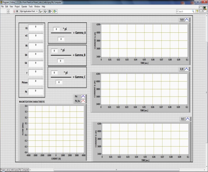 | Figure 2. The software application interface |
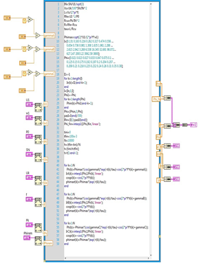 | Figure 3. Block diagram with MathScript Node code |
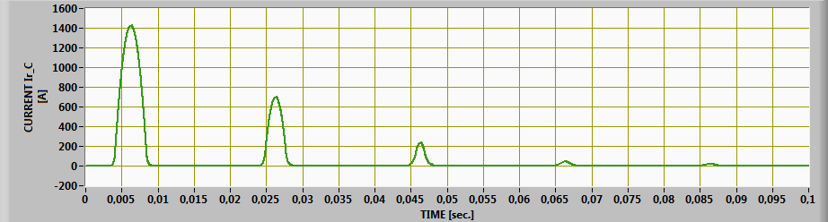
Visual inspection via graphing is essential in analyzing complex data sets. The single-plot XY graph accepts a cluster that contains an x array and a y array. The XY graph also accepts an array of points, where a point is a cluster that contains an x value and a y value. The bundle function is used to assemble individual elements into a single new cluster.The waveform for the inrush current on the three phases is accomplished with the functions block from Fig. 4.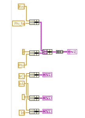 | Figure 4. XY graph of the waveform for inrush current on the three phases |
4. Simulation Results
To simulate the transient phenomenon occurring when connecting the transformer to the mains, a 15 MVA, 10.5/6.3 kV transformer, with delta/delta connection was used.The modeling of the phenomenon occurring when connecting the transformer to the mains was achieved using the software application interface developed with LabVIEW software.By determining the flux values with eq. (4), based on the magnetization curve [1, 5, 6, 9, 15, 16], provided by the producer (Fig. 5), we will determine the values of the inrush current.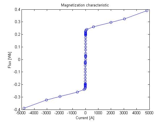 | Figure 5. Magnetization characteristic transposing |
We achieved a transposition of the magnetization curve, made available by the transformer producing company, instead of its representation according to the magnetic field (H) - magnetic induction (B), we get a representation according to the flow  - current (I).The inrush current reaches the peak value of 3711 A, on phase A, where the phase angle is zero and the voltage when connecting the transformer to the mains passes through zero (see Fig. 6).
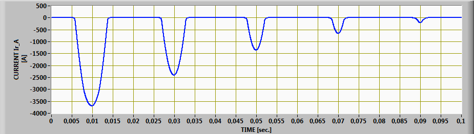 | Figure 6. The waveform for inrush current on phase A, achieved using LabVIEW software |
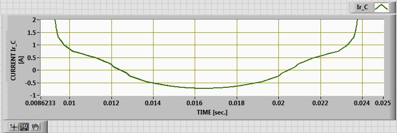
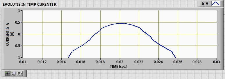 | Figure 7. The waveform for Inrush current on phase A near to zero |
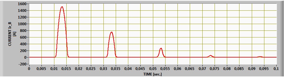 | Figure 8. The waveform for inrush current on phase B achieved using LabVIEW software |
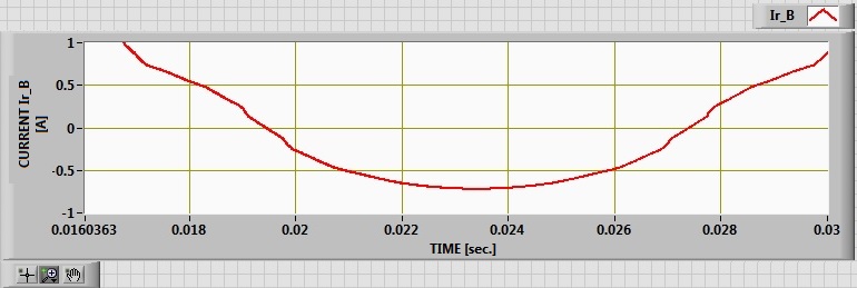 | Figure 9. The waveform for Inrush current on phase B near to zero |
 | Figure 10. The waveform for Inrush current on phase C achieved using LabVIEW software |
 | Figure 11. The waveform for Inrush current on phase C near to zero |
The inrush current on phase B reaches values of approximately 1513 A, and  (as in Fig. 8). On phase C, the current reaches 1419 A, and
  (see Fig. 10).
5. Experimental Results
Fig. 12 shows the diagram used for testing the transformer when connecting it to the mains.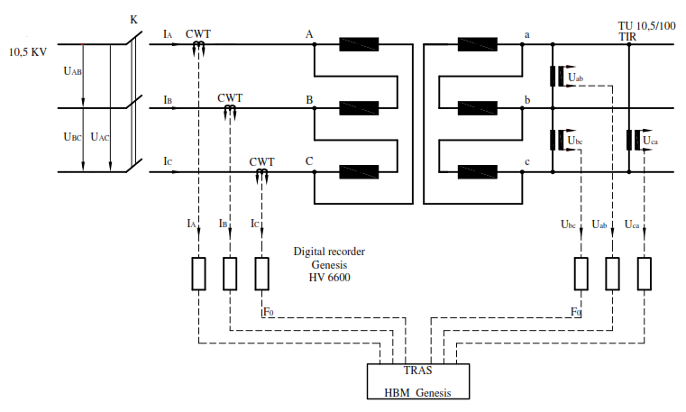 | Figure 12. The transformer testing diagram for the experimental tests |
The testing scheme includes instrument voltage transformers, Rogowski coils (CW), equipment for system data recording and acquisition (Digital recorder Genesis HV 6600 TRAS HBM Genesis). Rogowski coils are used for current monitoring in precision systems.The Genesis High Speed Transient Recorders and Data Acquisition Systems share the highest sample rates and mid to high channel counts. Based on modular platforms, all can be configured according to the requirements of the application, whether a single channel or thousands of channels.The Genesis High Speed family has signal conditioners for many types of sensors. Many of the modules offer isolated inputs, even for high voltage inputs, allowing safe measurement of phase to phase voltage signals. The sample rates range from 20 kS/s to 100 MS/s per channel. Systems are out-of-the-box and easy-to-use.Genesis Highspeed is a unit which consists of independent digital modules; signal conditioning modules and a data acquisition system- combining a transient data recorder with a data acquisition system; - combining the time-domain performance with the frequency domain performance;- transient RAM memory at 100 Mega Samples per channel in parallel (400ms on one channel);- insulated and non-insulated channels;- unlimited size and time of recording;- Hi-Fi signal conditioning;- enabling viewing and control anywhere in the computer-connected network.On-line setup, monitoring and control can be carried out from any PC, by using Perception dedicated software, inclusively through fiber-optic networks.Genesis Highspeed central servers include a communication module for intranet connection (1 GBit).The inrush current waveforms were obtained as a result of the test carried out when connecting the transformer to the mains.Fig. 13 shows the waveforms for voltage and inrush current on phase A: the transformer was connected when the voltage passed through zero and the peak value of the inrush current equals 3717 A. It can be seen that the peak value occurs at 
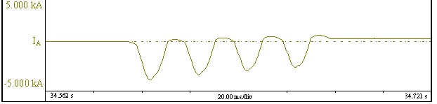 | Figure 13. The transformer testing diagram for the experimental tests |
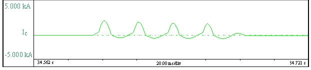
The inrush current on phases B and C has a lower value compared to the inrush current value on phase A, 1521 A current occurs on phase B (as in Fig.14) and 1412 A current on phase C (see Fig.15). This appears due to a different time at the connection.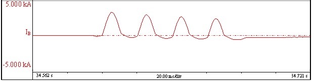 | Figure 14. The transformer testing diagram for the experimental tests |
 | Figure 15. The transformer testing diagram for the experimental tests |
6. Conclusions
In order to limit the consequences of excess transient current, technical solutions are available for implementation in the power system (controlled connection of transformer phases, fastening the protections at high levels during connection) and solutions relating to the design, ensuring an acceptable level of transient current.In this paper we propose to determine the value of the inrush current for adopting suitable protecting equipment.It can be seen that the transient regime occurring when connecting the transformer to the mains lasts for a few seconds, after which it is damped according to an exponential equation - which depends on the primary resistance and on the flux variation in time.When coupling the transformer to the terminals of phase A at the initial time, the voltage is close to zero, as well as when the most important shock occurs. This was demonstrated both by simulation of the phenomenon using the software application interface developed with LabVIEW software and by experimental tests.The value of the inrush current which occurs when the transformer is connected to the mains depends on the time of connection of the transformer to the mains and the initial phase angle  The mathematical model proposed in this paper can be easily extended for other types of power transformers, to predetermine the size of the inrush current.There is always a difference between the virtual model adjusted to the phenomenon under study and the actual construction of the transformer due to objective deviations between the transformer design dimensions and real dimensions resulting from its construction.In the submitted application, the differences noticed are due to inaccurate assessments of the make current damping. This deviation will not affect the use of the virtual model for practical applications focusing on the peak current for protection programming. Taking into consideration this requirement, the achieved virtual model is more than acceptable. The virtual model can also be used in the transformer design stage when calculating electrodynamic forces occurring in transformer windings which are dependent on the peak current generated when connecting the transformer to the mains.The experimental results presented for predetermination of the power transformer inrush current validate the theoretical study and are consistent with the simulation results.There is always a difference between the virtual model adjusted to the the studied phenomenon and the actual design of the transformer due to objective deviations between the transformer design dimensions and the actual dimensions resulting from its execution.
References
| [1] | M.C. Nițu, V. Voicu, M. Duță, P.M. Nicolae, Ensuring the Security of the Energy System by Predetermining the Size of Inrush Current at Power Transformers Coupling, in: Proceedings of 16th International Conference on Computer as a Tool- EUROCON, 2015, pp. 1-4. |
| [2] | I.S. Gheorghiu, A.S. Fransua, Treat on Electric Machines, vol. II, A.R.S.R, Romania, 1970. |
| [3] | Y. Cui, S.G. Abdulsalam, S. Chen, W. Xu, A sequential phase energization technique for transformer inrush current reduction- Part I: Simulation and experimental results, in: IEEE Transactions on Power Delivery, 2005, vol.20, no.2, pp. 943-949. |
| [4] | W. Xu , S.G. Abdulsalam, Y. Cui, X. Liu, A sequential phase energization technique for transformer inrush current reduction- Part II- Theoretical analysis and design guide, in: IEEE Transactions on Power Delivery, 2005, vol.20, no.2, pp. 950-957. |
| [5] | C.E. Lin, C.L. Cheng, C.L. Huang, J.C. Yeh, Investigation of magnetizing inrush current in transformers Part I-Numerical Simulation, in: IEEE Transactions on Power Delivery, 1993, vol 8, no.1, pp. 246-253. |
| [6] | C.E. Lin, C.L. Cheng, C.L. Huang, J.C. Yeh, Investigation of magnetizing inrush current in transformers Part II-Harmonic Analysis, IEEE Transactions on Power Delivery, 1993, vol. 8, no.1, pp. 255-263. |
| [7] | M.C. Nițu, M. Duță, C.I. Nicola, Predetermining the size of inrush current in power transformers coupling using LabVIEW, in: Proceedings of 2016 International Conference on Hydraulics and Pneumatics - HERVEX, 2016, pp. 1-10. |
| [8] | I.S. Gheorghiu, A.S. Fransua, Treat on Electric Machines, vol. II, A.R.S.R, Romania, 1970. |
| [9] | M.G. Vanti, S.L. Bertoli, S.H. Cabral, A.G. Gerent, P. Kuo-Peng, Semianalytic solution for a simple model of inrush currents in transformers, in: IEEE Transactions on Magnetics, 2008, vol. 44, no.6, pp. 1270 – 1273. |
| [10] | A.W. Rawool, S.V. Kulkarni, P.P. Vaidya, LabVIEW based electrical partial discharge measurement system, in: International Journal of Electrical and Electronics Research, 2015, vol.3, pp. 76-80. |
| [11] | J.A.B. Grimoni, O.S. Nakao, Using LabVIEW in a Mini Power System Model Allowing Remote Accessand New Implementations, in: Proceedings of International Conference on Engineering Education - ICEE, 2007, pp.1-5. |
| [12] | Introduction to Modern Data Acquisition with LabVIEW and MATLAB http://www.phys.utk.edu/labs/modphys/Introduction_to_Modern_Data_Acquisition[1].pdf. |
| [13] | LabVIEW MathScript RT Module. http://0x9.me/8pybq |
| [14] | R.W. Larsen, LabVIEW for Engineers, Pearson Education, Inc., publishing as Prentice Hall, New Jersey, USA, 2010. |
| [15] | L. Mandache, D. Topan, M. Iordache, I.G. Sirbu, SPICE model for effective and accurate time domain simulation of power transformers, in: Proceedings of Nonlinear Dynamics and Synchronization (INDS) & 16th International Symposium on Theoretical Electrical Engineering (ISTET), 2011, pp. 1-6. |
| [16] | P. Rafajdus, P. Bracinik, V. Hrabovcova, J. Saitz, L. Kankula, Current transformer analysis under transient conditions, in: Proceedings of XIX International Conference on Electrical Machines (ICEM), 2010, pp. 1-5. |

 Abstract
 Reference
 Full-Text PDF
 Full-text HTML