Santosh Joteppa , Chandrashekar BK , Vinod S. Chippalkatti
Design and Engineering, Centum Electronics Ltd., Bangalore India
Correspondence to: Chandrashekar BK , Design and Engineering, Centum Electronics Ltd., Bangalore India.
| Email: |  |
Copyright © 2017 Scientific & Academic Publishing. All Rights Reserved.
This work is licensed under the Creative Commons Attribution International License (CC BY).
http://creativecommons.org/licenses/by/4.0/

Abstract
OCXO’s (Oven Controlled Crystal Oscillators) are used to control the stringent frequency stability requirements which is not possible in basic crystal oscillators or TCXO’s. When these OCXO’s are used under dynamic load condition, the electrical parameter - phase noise shall get disturb/degrade and ending up with deviation in the required precision frequency for which it is designed. Mechanical design of such OCXO has the limitation in terms of amount of vibration being transferred to the crystal. To minimize the amount of vibration transfer to the crystal, one needs to use the isolators/dampers having good damping co-efficient. This paper explains the design, development, testing and qualification of OCXO to meet the precise frequency requirements under dynamic condition, also the details about the selection of isolators/dampers and mounting conditions to arrive at the better and acceptable results under dynamic load condition.
Keywords:
OCXO, Isolator, Damping, Phase Noise, Random Vibration, FEA
Cite this paper: Santosh Joteppa , Chandrashekar BK , Vinod S. Chippalkatti , Design Optimization of OCXO to Fulfil the Phase Noise Requirement under Dynamic Load Condition, Journal of Mechanical Engineering and Automation, Vol. 7 No. 2, 2017, pp. 23-29. doi: 10.5923/j.jmea.20170702.01.
1. Introduction
Oven Controlled Crystal Oscillator (OCXO) is typically used in high precision frequency application such as frequency generating circuits of satellite hardware and navigational aids where frequency stability requirement is more stringent.The three main parts of an OCXO are the piezoelectric crystal, the sustaining circuit and the oven. The piezoelectric crystal and other temperature sensitive components are placed inside the ovenized enclosure which accommodate a temperature sensor, a heating element and the oven control circuits to maintain the temperature stabilized environment, thus isolate the crystal from external temperature variation. Keeping the crystal at a constant temperature greatly improves the oscillator performance and frequency accuracy. The performance of the crystal depends on various factors like use of different crystal cuts, operating temperature - usually it is in the range of 80° to 100°C and other parameters. Figure 1 shows the block diagram of a typical OCXO [1], the basic elements in the sustaining circuits are amplifier, crystal resonator and voltage tuner. The amplifier of a crystal oscillator consists of atleast one active device, the necessary biasing networks and may include other elements for band limiting, impedance matching and gain control. The crystal resonator helps in controlling the feedback network and a variable capacitor for voltage tuning. 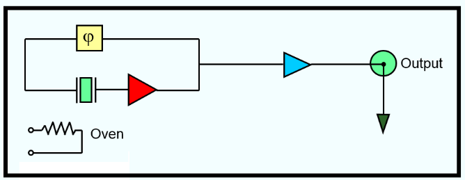 | Figure 1. Block diagram of typical Oven controlled crystal oscillator |
2. Background
The Frequency of the crystal, which is called as the heart of oscillator, directly depends on the dynamic behavior of the mechanical parts of OCXO unit. Suppose the fundamental frequency of the mechanical parts overlap with the operational frequency range of crystal, resulting in huge amplification which indirectly affects the phase noise and in-turn impacts on the required precision frequency. In the present paper, how the OCXO design is optimized innovatively to achieve the required low fundamental frequency of the system and acceptable phase noise level is explained in detail.
3. Design Description
The OCXO encloses a crystal in a temperature controlled chamber called an oven. Frequency stability is achieved by maintaining tight temperature control of the crystal within the oscillator oven. Care must be taken not to wick thermal energy away from the OCXO and continuously maintain the thermal equilibrium. When an OCXO is turned on, it goes through a warm-up period, while the temperature of the crystal in the internal oven stabilizes at a temperature significantly warmer than ambient. During warm-up, the performance of the oscillator will not meet the specified frequency stability until normal operating temperature is reached. Once the oven is bridged, the temperature within the oven remains constant as ambient varies. The oven controller operates such that if the internal temperature of the oven decreases due to an ambient temperature drop, the oven controller will provide more power to compensate for thermal losses. Similarly, an increase in ambient temperature causes a reduction in applied power into the oven and the compensation temperature decreases. In most modern designs additional heat is considered as problem and will cause most devices to degrade in performance or eventually fail where as in OCXO, the heat generated within the OCXO oven is utilized to maintain a constant temperature at the crystal.In a typical OCXO, The oven which accommodates the crystal will be mounted on the main PCB with the help of pins; the number of pins in the oven will differ from package to package. Based on the application, main PCB is placed inside the different sized mechanical housings and it is being closed by a cover plate. In a current design the main PCB is being placed inside the mechanical housing and which is closed with a cover plate. The oven and its lid is designed using KOVAR material [2], Aluminum alloy 6061 T6 is selected to design all other mechanical parts and SS Grade A2 bolts are selected for parts assembly. The construction of the housings are the typical one piece package body milled out from the respective material blocks, the outer housing is fabricated along with four mounting lugs.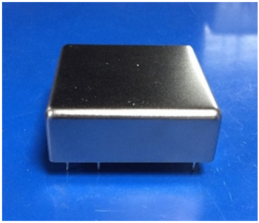 | Figure 2. Typical Oven |
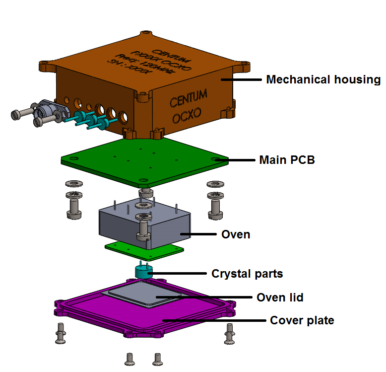 | Figure 3. Current OCXO design |
4. Realization
This section explains the details of design and analysis iterations that have been carried out for OCXO to meet the required precise frequency and electronic parameters. The unit should have the first fundamental frequency less than 50Hz and no further amplification peaks should observe throughout the operating frequency range to meet the acceptable phase noise level [3]. The numerical code- Finite element analysis (FEA) is used to study the dynamic behavior of current OCXO design using virtual prototype which is equivalent to flight or qualification model. The FEA results are analyzed thoroughly and the OCXO unit is subjected to physical vibration test and phase noise is measured during vibration to verify the design.
4.1. Finite Element Analysis
FEM is a numerical procedure for solving the physical problems governed by a differential equation or an energy theorem and it provides an approximate solution [4]. A general-purpose commercial software Hypermesh is employed to discretize the geometry with the aid of two dimension shell and three dimensional tetrahedron elements. Optistruct solver is used to conduct the dynamic simulation of the unit. The finite element model of OCXO assembly is shown in Figure 4. 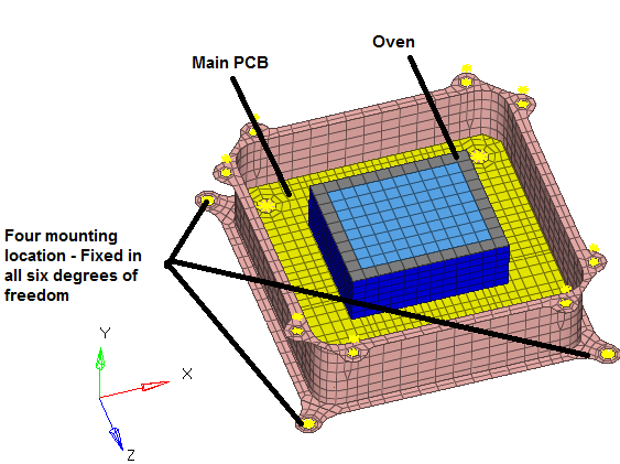 | Figure 4. FE model of OCXO assembly without cover |
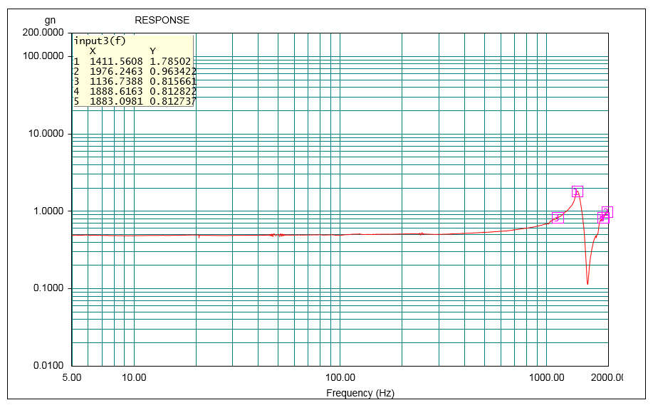
The first fundamental frequency of the OCXO design is found at 1153 Hz in finite element analysis and 1136Hz from physical testing. It is considered to be very high and resulting in huge phase noise shift. 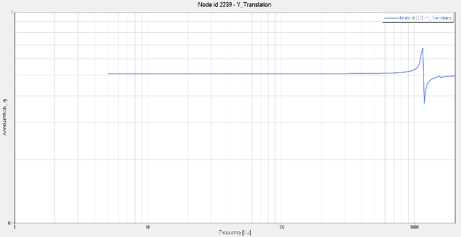 | Figure 5. Resonance plot from the Analysis |
 | Figure 6. Resonance plot from the Testing |
Both finite element analysis and physical testing result shows a very high frequency for the first mode of vibration and multiple amplifications as proceeds, which depict the variation in electronic performance – phase noise and noise levels which in-turn results in failure of OCXO in giving the required precision frequency for which it is designed.In order to achieve the lower fundamental frequency and minimal acceleration peaks, the OCXO mounting method has been modified. The OCXO assembly is again attached to another large mechanical housing as a suspend part with the help of isolators/dampers made of silicone rubber bearing high mechanical property [5]. Two isolator configurations have been chosen to optimize the design in order to achieve the requirements. Further, using this configuration, three different mounting methods have been employed, details of this is explained in the later sections.
4.2. Isolator
Based on the detailed analysis and testing of dynamic behavioral study of OCXO, achieving the required precise frequency was found to be very difficult. Thus, the isolators/dampers are utilized in the design to meet the requirement. The isolation is not the only feature to be taken into account when determining vibration isolation. Indeed, the features of elastomers used in isolators also depend on other factors such as a. Temperatureb. Dynamic stressc. Frequencyd. Work rateThese factors affecting the suspension behavior in their operation area and they are dependent on the inherent characteristics of the rubber such as modules, damping factors and other factors such as shape, external loads and deformation rate.The Acceleration transmitted to the equipment/OCXO corresponds to the stress acceleration, but it is noteworthy that even if the acceleration level is not reduced beyond certain frequency range. Using isolator will help in filtering the high frequency resonance that is often damageable for the equipment/OCXO [6, 7].
4.2.1. Isolator Configurations
The isolators are made of high mechanical properties rubber with high damping in order to reach “Q” quality factor less than 3. Approximate weight of this isolator is very less and it can suspend the mass up to 800 grams. The operative temperature range is from -55 deg C to +150 deg C for these type of silicon made isolators and allow to obtain low frequency behavior under high stress [7, 8].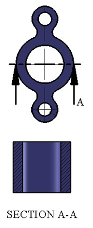 | Figure 7. Isolator configuration 1 – Cylindrical type |
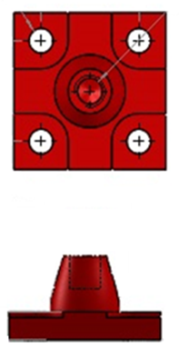 | Figure 8. Isolator Configuration –2- Square type |
These isolators are typically used in data processing equipment, medical electronics, video recorders, disk drive and small sensitive equipment mounted on carriers or on fixed stations.
4.3. Mounting Methods
The OCXO is designed with three mounting methods and the finite element analysis is performed for all three mounting methods refer Figure 9 to Figure 11 using virtual prototypes which are equivalent to the flight/qualification model.The Finite element analysis results of all the three designs are analyzed thoroughly and the best mounting method among three is finalized based on the obtained fundamental frequencies and amplification level [8]. 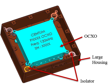 | Figure 9. Mounting method 1 |
The OCXO design with mounting method 1, the unit is suspended inside the large housing by means of four isolators (Isolator configuration 1- Cylindrical type) at the four corners using stainless steel screws.The OCXO design with mounting method 2, unit is suspended using four isolators (Isolator configuration 2- Square type). Two number of isolators are utilized on two opposite sides of the OCXO refer Figure 10.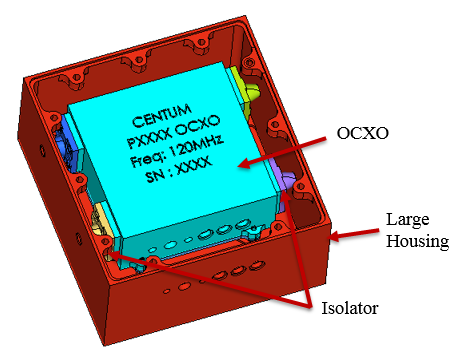 | Figure 10. Mounting method 2 |
The OCXO design with mounting method 3 is similar to OCXO design with mounting method 2. But in this design, only one number of isolator is used on each side of the OCXO to suspend OCXO unit inside the large housing.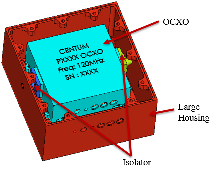 | Figure 11. Mounting method 3 |
4.4. Finite Element Analysis of OCXO with Isolators
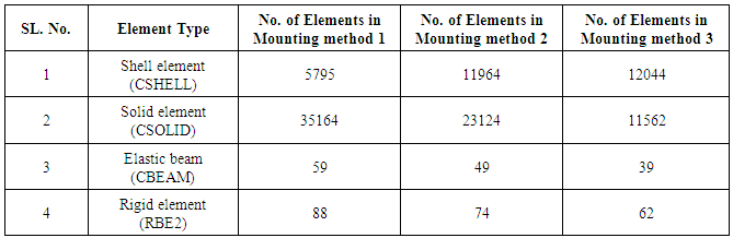
The same finite element model of the previous OCXO design is considered, along with that outer mechanical housing and cover plate are modeled. The isolators are modeled using shell and hexahedron elements with silicone elastic property. The connection of isolators to outer housing and OCXO unit is modeled using elastic beam and rigid (RBE2) elements. The Finite element model detail is shown in Table 4.1.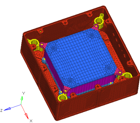 | Figure 12. FE Model - Mounting method 1 |
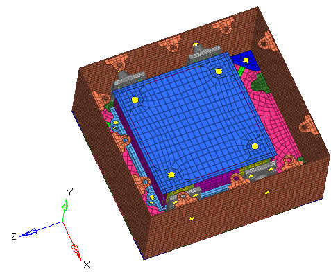 | Figure 13. FE Model - Mounting method 2 |
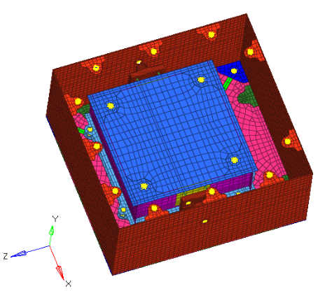 | Figure 14. FE Model - Mounting method 3 |
Table 4.1. Finite Element model details
 |
| |
|
4.4.1. Analysis and Result Discussion
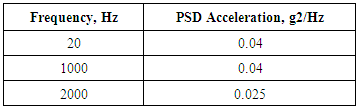
The following analyses are performed for all the three designs, 1. Eigen value analysis2. Sine response analysis3. Random response analysisFollowing are the basic parameters considered for finalizing the design,a. The first fundamental frequency should be less than 50 Hz (since phase noise will be measured above this frequency).b. The OCXO unit should not have high amplification at its first mode and no further amplifications (peaks) should observe after first mode. c. Isolator damping effect in the frequency range of testing.The Eigen value analysis is performed by fixing the OCXO at four mounting location in all six degrees of freedom refer Figure 16. Based on the Eigen value analysis result, the virtual prototypes are subjected to Sine response simulation for 0.5g, 5g and 20g acceleration, the response is extracted at the selected point where the maximum deformation is observed in Eigen value analysis of all the three designs. The response for 0.5g acceleration input alone is discussed in this paper. The response for 5g and 20g for all the three designs are also obtained in the similar fashion as obtained for 0.5g with higher magnitude. Random response analysis is performed for the PSD load as shown in Table 4.2, responses are extracted at the same probe location considered in sine response analysis, which are identified based on the Eigen value analysis [9-11].Table 4.2. PSD load for Random response simulation
 |
| |
|
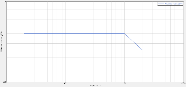 | Figure 15. Random input plot (PSD curve) |
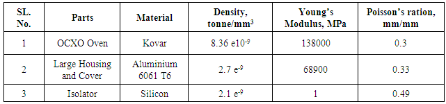
Table 4.3. Material Specification
 |
| |
|
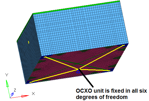 | Figure 16. Boundary Condition for OCXO |
Result - Mounting method -1The fundamental frequency of the OCXO design with mounting method 1 is found at 19 Hz with a peak acceleration of 2.5g. From plot it is observed that there is only one peak (at first fundamental frequency) and there after no peaks are observed and the response is continuously getting decayed with frequency proceeds. The response from the random analysis also shows continuous decrease in PSD acceleration with acceptable overall Grms level. The plots are shown in Figure 17 and Figure 18.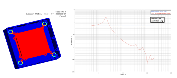 | Figure 17. Eigen value and Sine response plot - Mounting Method – 1 |
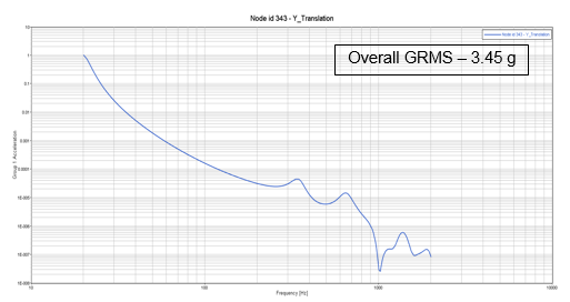 | Figure 18. Random response plot - Mounting method – 1 |
Result - Mounting method 2The fundamental frequency of the OCXO design with mounting method 2 is found at 22 Hz with a peak acceleration of 2.56g. From plot, it is observed that the peak acceleration is observed at first fundamental frequency and is getting decay with increasing frequency continuously. The random response plot also depicts the continuous lowering in PSD acceleration as the frequency proceeds with acceptable overall Grms level, refer Figure 19 and Figure 20.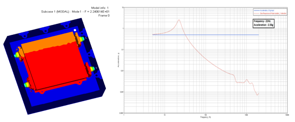 | Figure 19. Eigen value and Sine response plot - Mounting method 2 |
 | Figure 20. Random response plot - Mounting method 2 |
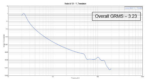
Result - Mounting method 3The fundamental frequency of the OCXO design with mounting method 3 is found at 16 Hz with peak acceleration of 2.5g. Here also like previous designs (Mounting method 1 & 2) after the first peak acceleration which is observed at the first mode, response descends continuously with frequency and the random response also shows the same, reduction in PSD acceleration along frequency with acceptable overall Grms level, refer Figure 21 and Figure 22.From the response of all the three mounting methods, the design with mounting method 3 shows the best dynamic behavior since the first mode is observed very early at 16Hz having acceptable peak acceleration and overall Grms levels. 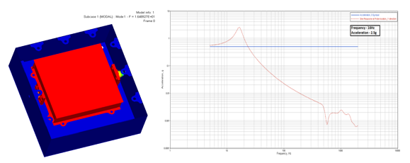 | Figure 21. Eigen value and Sine response plot - Mounting method 3 |
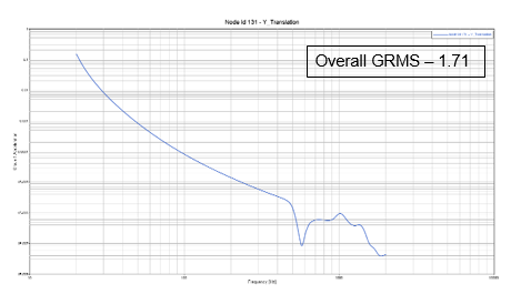 | Figure 22. Random response plot - Mounting method 3 |
5. Conclusions
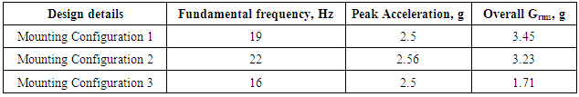
The finite element analysis results of all the three design with different mounting methods are tabulated in the Table 5.1.Table 5.1. Finite Element analysis results
 |
| |
|
From the above tabulated results it is observed that, the dynamic behavior of OCXO with all the three mounting methods are meeting the basic parameters such as the first fundamental frequency shall fall below 50Hz and continuous decrease in the response after the first mode. Among three mounting methods, mounting method 3 showed the best dynamic behavior. But with the past work and previous experience in the same field, a unit mounting with single isolator on both side may prone to critical vibration modes and in turn failure of the product may not suddenly but definitely in future. Thus, the OCXO design with mounting method 1, which is the next best design chosen and finalized for the fabrication.The OCXO design with mounting method 1 is then fabricated and tested. The physical test results are well in agreement with the analysis results. The electrical parameter - phase noise is measured less than -125db at 100Hz frequency during vibration, which is acceptable for OCXO to consign the desired precision frequency without any drawbacks.
References
| [1] | John R. Vig “Quartz Crystal Resonators and Oscillators” US Army Communications-Electronics Research, Development & Engineering Center Fort Monmouth, NJ, USA. |
| [2] | Carpenter data sheet for kovar material. |
| [3] | Kay Gheen “Phase noise measurement methods and techniques” Agilent technologies. |
| [4] | Nitin s gokhale, Sanjay S Deshpande, Sanjeev V Bedekar, Anand N Thite “ Practical Finite Element Analysis, by Finite To infinite. |
| [5] | G. P. O Hara “Mechanical properties of silicone rubber in a closed volume”. |
| [6] | Warren C. Young and Richard G. Budynas “Roark’s formulas for Stress and strain” McGraw-Hill Publishers, eighth edition, New Delhi. |
| [7] | Dave S. Steinberg “Vibration analysis for Electronic Equipment” A Wiley-Inter science Publications. |
| [8] | Steinberg, D.S. “Preventing Thermal Cycling and Vibration Failures in Electronic Equipment” Wiley (New York, 2001). |
| [9] | William T. Thomson and Marie Dillon Dahleh “Theory of Vibration with Applications” Pearson Publication, Fifth Edition. |
| [10] | Cyril M. Harris and Allan G. Piersol “Harry’s Shock and Vibration hand book” McGraw-Hill Publishers, fifth edition. |
| [11] | C. E Beards “Structural Vibration: Analysis and Damping” Arnold - a member of the Hodder Headline Group. |
| [12] | Døssing, O. Structural Testing Part 1: Mechanical Mobility Measurement. Bruel and Kjaer |
| [13] | John R. Vig “Quartz Crystal Resonators and Oscillators” US Army Communications-Electronics Research, Development & Engineering Center Fort Monmouth, NJ, USA |
| [14] | G. Gautschi “Piezoelectric Sensorics” Springer-Verlag Berlin Heidelberg 2002. |
| [15] | Veprik A. M, Babitsky, (2000) “Vibration Protection of Sensitive Electronic Equipment from Harsh Harmonic Vibration” Journal of Sound and Vibration, Vol. 238(1), pp. 19-30. |
| [16] | Mark R Probst., (1979) “Viscoelastic Polymer for Printed Circuit Board Vibration Damping” a technical report of U.S Army Electronics Research and Development Command, Harry Diamond Laboratories. |

 Abstract
 Reference
 Full-Text PDF
 Full-text HTML