Journal of Mechanical Engineering and Automation

p-ISSN: 2163-2405    e-ISSN: 2163-2413

2017;  7(1): 1-7

doi:10.5923/j.jmea.20170701.01


Effect of Heater System on Heating Efficiency and Interfacial Properties between Prepreg and Injected Part in Hybrid Molding

Masaki Ohishi1, Akio Ohtani2, Asami Nakai3

1Satoh Machinery Works Co., ltd, Advanced Fibro-Science, Kyoto Institute of Technology, Aichi, Japan

2Institute for Foundational Education and Research, Educational Program Center, Kyoto Institute of Technology, Kyoto, Japan

3Department of Mechanical Engineering, Faculty of Engineering, Gifu University, Gifu, Japan

Correspondence to: Akio Ohtani, Institute for Foundational Education and Research, Educational Program Center, Kyoto Institute of Technology, Kyoto, Japan.

Email:

Copyright © 2017 Scientific & Academic Publishing. All Rights Reserved.

This work is licensed under the Creative Commons Attribution International License (CC BY).
http://creativecommons.org/licenses/by/4.0/

Abstract

Hybrid molding is the combining molding process of stamping and injection moldings for Fiber Reinforced Thermoplastics (FRTP), therefore composite structural materials with many members or rib structure behind molding products can be fabricated at one time by using this process. However, molding conditions effects on the interfacial properties between pre-heated part and injected resin have not been investigated before. In this study, three types of heating system such as far-infrared heater with ceramic heating element, middle-infrared heater with metal heating element, and middle-infrared heater with carbon heating element were used to examine heating time, temperature distribution, and amount of electric power for the efficiency of prepreg heating by hybrid molding. Also, prepreg was preheated by using these heating systems. By including the fact from mechanical properties of hybrid products, the most efficient heating method for hybrid molding was investigated. From these results show that most efficient heater system was metal heater with middle infrared ray for preheating of CF/PA6 thermoplastics composite in hybrid molding.

Keywords: GFRTP, CFRTP, Hybrid molding, Thermoplastic, Preheat

Cite this paper: Masaki Ohishi, Akio Ohtani, Asami Nakai, Effect of Heater System on Heating Efficiency and Interfacial Properties between Prepreg and Injected Part in Hybrid Molding, Journal of Mechanical Engineering and Automation, Vol. 7 No. 1, 2017, pp. 1-7. doi: 10.5923/j.jmea.20170701.01.

1. Introduction

As global environmental conservation grows significantly around the world, automobile makers are paying a lot of effort on working to make cars lighter to reduce fuel using and CO2 emissions [1, 2]. Composite materials such as carbon fiber reinforced plastics have been adopted in automotive parts. Among them, Fiber Reinforced Thermoplastics (FRTP) which has advantages such as recycling, high cycle time forming and secondary workability have been focused on. [3-5] Hybrid molding is one of the molding method to fabricate FRTP [6-9]. It combines injection molding with short fibers containing molten resin and press forming with preheated continuous fiber prepreg, which is typical in several hybrid molding methods [10, 11]. This method is able to combine the injected resin and preheated prepreg at one time, and it has advantages without requiring post-process such as drilling, trim, bonding and so on. In the molding of FRTP, various factors like thermal condition, transfer method, forming condition have effect on mechanical properties of molding product [12-18]. Therefore, optimization and understanding of molding conditions are very important for quality improvement of the molding product in hybrid molding. However, there are no previous studies about molding conditions effect on quality of molding product especially interfacial properties between prepreg and injected part. Hybrid molding has preheat process to be softened prepreg by heater. It is necessary to heat prepreg to uniform temperature distribution in shorter time for stable quality with high production efficiency [19-22]. In this study, the effect of using different heating system for preheating prepreg, such as middle and far infrared heater on temperature history of hearting and temperature distribution of prepreg surface after heating were investigated. Moreover, interfacial strength between prepreg and injected resinof products preheated by different heating system was compared.

2. Explanation of Hybrid Molding

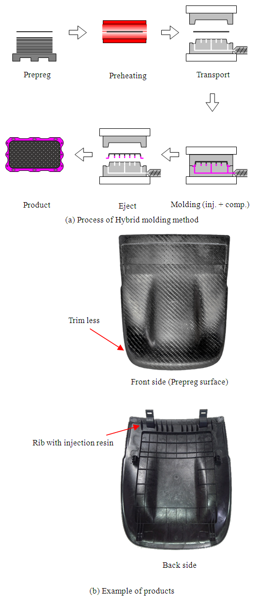
Fig. 1 shows hybrid molding process and example of hybrid molding products. As shown in Fig. 1 (a), firstly, prepreg sheet is put on the sheet feeding machine. Then sheet feeding machine transports prepreg sheet to a heater or an oven for preheating to soften it. After preheating under the predetermined temperature for some time, prepreg sheet will be transported to the press machine and set on the mold. In this process, prepreg is shaped under press which is given by press machine and at the same time molten resin injects to make rib structure or attach portion by injection machine. Injected resin as well as prepreg is consolidated at one time. In the end, after ejection process final products are obtained. Hybrid molding has several advantages. For example, it is high cycle molding method which is similar to injection molding and it can manufacture complicated product such as rib structure or products with mounting members, which reduce the cost without using prepreg material for whole structure.
Figure 1. Process of Hybrid molding method and example of products

3. Experiment and Discussion

3.1. Comparison Test of Heater Systems

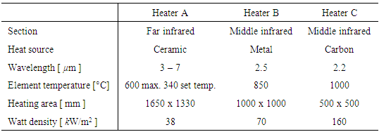
Table 1 shows specifications of heater system. Heater A has far infrared heater of ceramic heater element of which the highest heat generated temperature was 600°C. Heater B has middle infrared heater of metal heater element of which the highest heat generated temperature was 850°C. Heater C has middle infrared heater of carbon heater element in the quartz tube of which the highest heat generation temperature was 1000°C. Temperature of Heater A was controlled by thermocouple in the heater element. Temperature of Heater A was set to 340°C. Output power of Heater B and Heater C were adjusted automatically by measuring surface temperature of prepreg using radiation thermometer.
Table 1. Specification of heaters
     
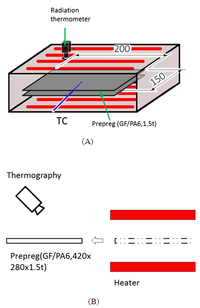
Fig. 2 shows two comparison test methods of the heating systems. Test A investigated the heating time until surface and center portion temperature of prepreg reach the target temperature. Two prepreg sheets with dimension of 200 x 150 x 1.5 mm constructed continuous glass fiber impregnated with PA6 nylon (TEPEX dynalite 102, Bond Laminates), were piled up. Center portion temperature was measured by thermocouple between two sheets. When measuring, products heated by Heater A with thermocouple placed on the upper surface of prepreg, while counterparts heated by Heater B and Heater C, temperature was measured by radiation thermometer with heating system. In Test B, temperature distribution of prepreg was measured just after heating (after 0 sec) and after 10 sec lapse when heating finished by using thermography camera. After 10 sec lapse measuring is because that the applicable time duration for measuring is from prepreg preheating end to resin injection start in hybrid molding. Target temperature of prepreg by hearting was 290°C. This temperature was decided in reference to data sheet of resin (Durethan BKV30 H2.0 LANXESS) to use for hybrid molding.
Figure 2. Measuring method of heating test
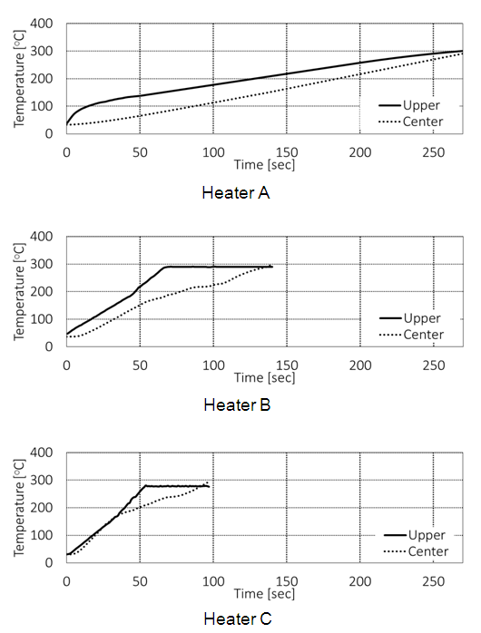
Fig. 3 shows temperature history of surface and center temperature of prepreg during heating. Heater C took the least time to reach target temperature. Heating time of Heater A was the longest, and it took about 2 and 2.5 times of heating time than the case of Heater B and Heater C. Heater temperature for Heater A was lower than other heaters, it was considered that in that case long heating time was needed. As a result, to prevent uneven heating the temperature setting of heating system with far infrared heater (Heater A) was normally 50°C higher than target temperature (set as 340°C) and temperature was raised by atmosphere heating in furnace. It was found that when temperature was around 290°C. Upper surface temperature of Heater B went up faster than Heater A and Heater B reached stable temperature time, which can be named as temperature reached time, was 180sec earlier than Heater A. However, in Heater B case center temperature reached time was required for additional 60 sec, while time of Heater A almost same with its upper surface. Heating control system of Heater B was controlled automatically by measuring prepreg surface temperature. When surface temperature reached 290°C, heater output would reduce and heat capacity decrease to guarantee surface temperature stable despite of low temperature in the center portion. Temperature rise trend of Heater C was similar to Heater B. However, Heater C had higher heat capacity than Heater B, and Heater C temperature reached time was faster than Heater B.
Figure 3. Relationships between heating time and temperature under Heater A, Heater B and Heater C
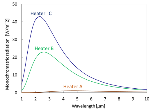
Fig. 4 shows relationship between wavelength and monochromatic radiation of each heater, it was calculated by Plank’s law. Area surrounded by X-axis and curved line shows radiation energy. Radiation energy of Heater C was largest and Heater A was smallest. Therefore Harter C had short heating time by large radiation energy and Heater A had long heating time by small radiation energy.
Figure 4. Relationship between wavelength and monochromatic radiation
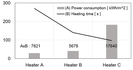
Fig. 5 shows power consumption and heating time of three heater systems. Heater A took the longest heating time and consumed lowest electric power. On the contrary, Heater C took the shortest heating time and consumed highest electric power consumption. Heater B had similar power consumption of Heater A, however relatively short heating time. It can be considered that the most efficient heating system is Heater B.
Figure 5. Power consumption and heating time
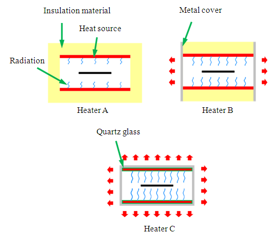
Figure 6 shows schematic diagram of the structure for each heater. Heat loss of Heater A was very small, because all side of heater was covered with insulation material. However, heating time was longer due to the lower radiation energy. Heater B had insulation material only at the upper and lower side. Both right and left sides were covered with steel plate. Heat loss was small and radiant heating with high efficiency was achieved. Heater C hadn’t insulation material. Therefor heat loss of Heater C was larger.
Figure 6. Schematic diagram of heater structure
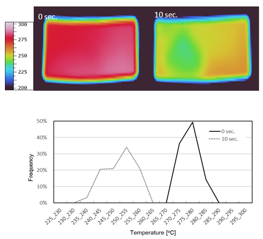
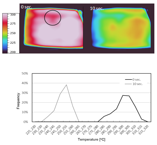
Fig. 7 to 9 shows prepreg surface temperature profile of each heating system just after heating and after the lapse of 10 seconds. In Heater A system, prepreg had nearest 290°C (setting temperature) and uniformed heating distribution. Surface temperature of prepreg after the lapse of 10 sec was lowered to 255°C. And it temperature only in prepreg center decreased 10°C in comparison with other part. The low temperature part of prepreg surface had delamination and swelling. Therefore it part had decreased heat transfer from inside of prepreg, and falling temperature of it part was increased.
Figure 7. Temperature profile of Heater A
Figure 8. Temperature profile of Heater B
Figure 9. Temperature profile of Heater C
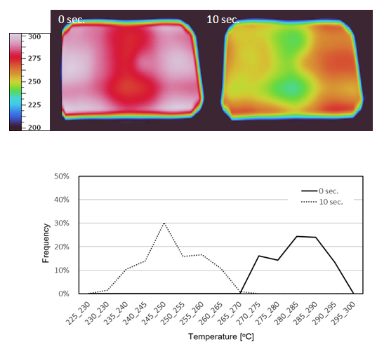
Prepreg just after heating by using Heater B was confirmed that it had lower temperature range in center. Center of Heater B had a hole in heating system, which was used for measuring prepreg temperature by using radiation thermometer from outside. Around the hole area there was no heating element, and it was difficult to heat near the hole. Temperature measured by radiation thermometer was low near the hole, while other part showed higher temperature than setting temperature.
Heater C had hole for temperature measuring. As shown in circle of Fig. 8, temperature of this part was low the same as Heater B. Low temperature range of Heater C was smaller than Heater B, because Heater C had small diameter hole as compared to Heater B. Radiation thermometer of Heater C was measured at low temperature range with the hole. Surface temperature except near the hole was overheated, because low temperature part was adjusted to setting temperature. Due to cover was no equipment for taking out sheet, left side of sheet temperature was low influence of outside air.
Table 2 shows sample variance calculated for temperature distribution of prepreg surface after heating. Sample variance just after heating with Heater A was smallest, and it with Heater B was biggest. Sample variance after laps of 10 sec with Heater B was biggest. It with Heater A was increased to almost same as Heater C. As a result, it was found that disturbance and swelling caused high temperature variance.
Table 2. Sample variance of temperature difference after heated
     

3.2. Interfacial Strength

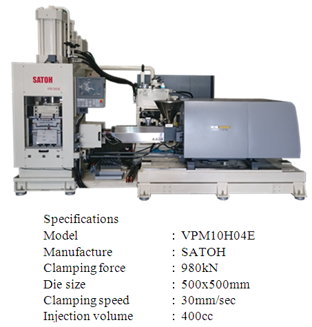
Hybrid molding was performed by using preheated prepreg sheet with three heater systems and interfacial strength between prepreg and injected resin rib was examined by tensile test. Fig. 10 shows Hybrid molding machine (VPM10H04E, manufactured Satoh Machinery) used in this study and the specifications. This machine had press machine of vertical type with maximum clamping force of 980kN and injection machine of horizontal type with injection capacity of 400cc.
Figure 10. Hybrid molding machine
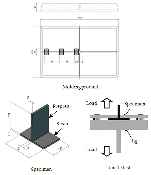
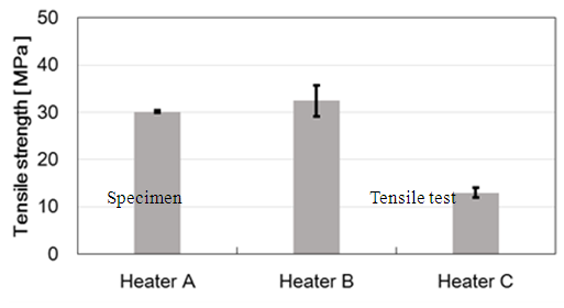
Fig. 11 shows molding product and size of specimen. Specimens were cut from gray parts of molding product. Tensile test was performed after mounting jig. Fig. 12 shows result of rib tensile test. Specimen heated under Heater B had the best interfacial strength, however it had high deviation. Surface temperature of prepreg after the lapse of 10 sec had wide range more than 40°C. It is consider that difference in prepreg sheet temperature resulted difference in interfacial strength. Interfacial strength of specimen heated under Heater A had no deviation. The reason was that prepreg heated under Heater A was near 290°C and had smaller temperature deviation after preheating. Lower interfacial strength was found in specimen heated under Heater C. Prepreg surface temperature just after heated by using Heater C shows over 300°C. Heat deterioration of matrix resin in prepreg was occurred excessive heating. Therefore specimen heated under Heater A had the lowest interfacial strength.
Figure 11. Molding product and tensile test jig
Figure 12. Tensile strength of ribs

4. Conclusions

The result shows that required performance of the heater system that can be efficiently heated. It was necessary to be equipped with low watt density and wave length in the vicinity of 2.5µm. The most efficient heater device was Heater B in this study. Uniform heating and preventing excessive heating were required for stability, in which way interfacial strength between prepreg and resin in hybrid molding can increase.

References

[1]  Szeteiová, K. (2010). Automotive materials: plastics in automotive markets today. Institute of Production Technologies, Machine Technologies and Materials, Faculty of Material Science and Technology in Trnava, Slovak University of Technology Bratislava. J. Breckling, Ed., The Analysis of Directional Time Series: Applications to Wind Speed and Direction, ser. Lecture Notes in Statistics. Berlin, Germany: Springer, 1989, vol. 61.
[2]  Köhler, J., Schade, W., Leduc, G., Wiesenthal, T., Schade, B., & Espinoza, L. T. (2013). Leaving fossil fuels behind? An innovation system analysis of low carbon cars. Journal of Cleaner Production, 48, 176-186. M. Wegmuller, J. P. von der Weid, P. Oberson, and N. Gisin, “High resolution fiber distributed measurements with coherent OFDR,” in Proc. ECOC’00, 2000, paper 11.3.4, p. 109.
[3]  Gallone, A., Ariante, M., Fusco, G., Flores, F. F., Bizzarro, G., Zinno, A., & Prota, A. (2012). THERMOPLASTIC COMPOSITE STRUCTURE FOR MASS TRANSIT VEHICLE: DESIGN, COMPUTATIONAL ENGINEERING AND EXPERIMENTAL VALIDATION. In 15th European Conference on Composite Materials. M. Shell. (2002) IEEEtran homepage on CTAN. [Online]. Available: http://www.ctan.org/tex-archive/macros/latex/contrib/supported/IEEEtran/.
[4]  (2011) Composites penetration growth in Automotive: towards mass production 2010-2020 trends and forecasts, JEC Composites, 13-22. “PDCA12-70 data sheet,” Opto Speed SA, Mezzovico, Switzerland.
[5]  Wilson, A. (2015). Automotive Composites. Textile Media Services Lt. J. Padhye, V. Firoiu, and D. Towsley, “A stochastic model of TCP Reno congestion avoidance and control,” Univ. of Massachusetts, Amherst, MA, CMPSCI Tech. Rep. 99-02, 1999.
[6]  Yanagimoto, J., & Ikeuchi, K. (2012). Sheet forming process of carbon fiber reinforced plastics for lightweight parts. CIRP Annals-Manufacturing Technology, 61(1), 247-250.Nayak, G. C., and Zienkiewicz, O. C., 1972, Convenient forms of stress invariants for plasticity, Proc. ASCE, 98(4), 949-953.
[7]  Bariani, P. F., Bruschi, S., Ghiotti, A., & Lucchetta, G. (2007). An approach to modelling the forming process of sheet metal-polymer composites. CIRP Annals-Manufacturing Technology, 56(1), 261-264.Owen, D. R. J., and Hinton, E., 1980, Finite elements in plasticity-theory and practice, Pineridge Press, Swansea.
[8]  rreira, P., Alves, N., Ramos, C., & Bartolo, P. J. (2013). Optimization of Thermoplastic Pre-Pregs Overmoulding. In Applied Mechanics and Materials, 365, 1007-1010. Trans Tech Publications. Poulos, H. G., 1971, Behavior of laterally loaded piles-I: Single piles., J. Soil Mech. and Found. Div., 97(5), 711–731.
[9]  Giusti, R., & Lucchetta, G. (2014). Modeling the adhesion bonding mechanism in overmolding hybrid structural parts for lightweight applications. Key Engineering Materials. Reese, L. C., and Welch, R. C., 1975, Lateral loading of deep foundations in stiff clay., J. Geotech. Engrg. Div., 101(7), 633–649.
[10]  Tanaka, K., Fujita, Y., & Katayama, T. (2015). Press and injection hybrid molding of glass fiber reinforced thermoplastics. WIT Transactions on Engineering Sciences, 90, 225-232.
[11]  Fiorotto, M., & Lucchetta, G. (2013). Experimental investigation of a new hybrid molding process to manufacture high-performance composites. International journal of material forming, 6(1), 179-185.
[12]  Wakeman, M. D., Zingraff, L., Bourban, P. E., Månson, J. A., & Blanchard, P. (2006). Stamp forming of carbon fibre/PA12 composites–A comparison of a reactive impregnation process and a commingled yarn system. Composites Science and Technology, 66(1), 19-35.
[13]  Hwang, S. F., & Hwang, K. J. (2002). Stamp forming of locally heated thermoplastic composites. Composites Part A: Applied Science and Manufacturing, 33(5), 669-676.
[14]  Zhang, Q., Cai, J., & Gao, Q. (2014). Simulation and experimental study on thermal deep drawing of carbon fiber woven composites. Journal of Materials Processing Technology, 214(4), 802-810.
[15]  Zhang, Q., Qiang, G. A. O., & Jin, C. A. I. (2014). Experimental and simulation research on thermal stamping of carbon fiber composite sheet. Transactions of Nonferrous Metals Society of China, 24(1), 217-223.
[16]  Wakeman, M. D., Cain, T. A., Rudd, C. D., Brooks, R., & Long, A. C. (1999). Compression moulding of glass and polypropylene composites for optimised macro-and micro-mechanical properties II. Glass-mat-reinforced thermoplastics. Composites science and technology, 59(5), 709-726.
[17]  Güllü, A., Özdemir, A., & Özdemir, E. (2006). Experimental investigation of the effect of glass fibres on the mechanical properties of polypropylene (PP) and polyamide 6 (PA6) plastics. Materials & design, 27(4), 316-323.
[18]  Susumu YAMAGUCHI. (1999). Study on Welding Mechanism of Injection Welding Process. Seikei-Kakou, 11(5), 440-2450 (in Japanese).
[19]  Cao, J., Xue, P., Peng, X., & Krishnan, N. (2003). An approach in modeling the temperature effect in thermo-stamping of woven composites. Composite Structures, 61(4), 413-420.
[20]  Machado, M., Murenu, L., Fischlschweiger, M., & Major, Z. (2016). Analysis of the thermomechanical shear behaviour of woven-reinforced thermoplastic-matrix composites during forming. Composites Part A: Applied Science and Manufacturing, 86, 39-48.
[21]  Brogan, M. T., & Monaghan, P. F. (1996). Thermal simulation of quartz tube infra-red heaters used in the processing of thermoplastic composites. Composites Part A: Applied Science and Manufacturing, 27(4), 301-306.
[22]  Labeas, G. N., Watiti, V. B., & Katsiropoulos, C. V. (2008). Thermomechanical simulation of infrared heating diaphragm forming process for thermoplastic parts. Journal of Thermoplastic Composite Materials, 21(4), 353-370.