Roger Oliva Felix , Thales Prini Franchi
Engineering College, FACENS, Sorocaba, São Paulo, Brazil
Correspondence to: Roger Oliva Felix , Engineering College, FACENS, Sorocaba, São Paulo, Brazil.
| Email: |  |
This work is licensed under the Creative Commons Attribution International License (CC BY).
http://creativecommons.org/licenses/by/4.0/

Abstract
The proposed project corresponds to a sealing system designed to perform simulations of air leaks in several industrial segments and gain control using low-cost controller. Its main objective is to evaluate the quality of the final product and can be applied to various industrial segments. The pneumatic system used in the prototype is fed with pressurized dry air, after filling the test piece with air, it waits to stabilize and measure the remaining flow through a mass flow sensor, directly indicating the volumetric leakage of the part under test. The leakage is simulated by opening and closing a flow regulator installed prior to the mass flow measurement system. This leakage is then compared to the adjusted parameters and obtains a possible approval of the part if it is within the conformities, depending on the acceptable flow rate provided by the final product manufacturer. The entire process of prototype automation has been developed an algorithm implementation on Open-Source platform using low-cost controller. The interest in further study of the chosen theme emerged for several reasons, including: to contribute to improving the performance and productivity of the processes in the industrial area; predict and prevent possible failures that cause environmental impact in the future; show that it is possible to achieve automation and sealing control system inexpensively, opting for a more cost-effective, since this market is becoming increasingly attractive to businesses.
Keywords:
Automation, Leak, Flow
Cite this paper: Roger Oliva Felix , Thales Prini Franchi , Automation and Leak Control System with Use of Clean Energy Supply (Compressed Air), Journal of Mechanical Engineering and Automation, Vol. 6 No. 6, 2016, pp. 141-150. doi: 10.5923/j.jmea.20160606.01.
1. Introduction
The flow of meaning corresponds to the act or effect of flow and move continuously. One of the contributions of the emergence of the term flow comes from Leonardo da Vinci in 1502. He noted that the amount of water per unit time which drained into a river corresponds to the same amount anywhere, regardless of the width, depth, slope and other factors [1].The development of practical devices for measuring fluid flow is possible from the industrial advancement, and with the aid of Bernoulli and researchers as Pitot. Such practical equipment are important both for blood flow measurements in the human artery and for liquid oxygen flow measurements on a rocket. Project research and industrial processes also depend on the flow measurement to perform analyses of materials and achieving results. Not only scientific laboratory technician is concerned with measuring the flow, but also the engineer who works in the industry cares about her, thus helping companies reduce the loss of fluids and achieve a higher profit [2].In industry, flow measurement is intended to account for the production of oil, gas, water and other fluids; to evaluate the performance of each of them; and obtain estimates on costs, fees and taxes, according to the rules of the donor agencies of each fluid. The quantity of liquids, gases or solids that pass a given location per unit of time can have different units of measure. The meters measure the volumetric type speed and understand the volumetric flow rate of the fluid from the speed and area of the cross section of pipe. Already the meters of the mass type have a specific pattern of measurement, the unit of mass is not derived from any other source, no variation affects the mass of fluid whose flow is being measured [3].One of the leak detection methods can be used in tanks and aircraft fuel systems where it uses helium gas as a leak tracer to exhibit a large enough sensitivity to ensure that the system is leak-tight, as well as the advantages of To use helium gas which is an inert gas. Other methods are used to identify the presence of leakage when it is large, thus avoiding pressurizing the tank with helium the exhaust gas. The importance of using the method is due to the possibility of relating a helium concentration to the presence of aeronautical fuel [4].Thus, the paper is structured as the following sections: automation devices used; pneumatic; experiment details; Tests and results; and final comments.
2. Automation Devices Used
Automation devices include all the tools necessary to carry out the automatic process, from the drivers to the end peripherals. In pneumatic automation components used are powered by compressed air, creating automated systems that facilitate the aid of man in production processes.Below are described some devices used in automation toward this purpose.
2.1. Controllers
The logic controller corresponds to a device that receives digital and analog variables in order to control the outputs according to the needs of the process or plant. It is a tool used in drives and control systems, so it is used widely in the industrial market, its internal structure is divided into three parts: inputs, the central processing unit and outputs. When entries are analog, the electronics module corresponds to A/D converters which convert an input signal to a digital value. All ready the analog outputs using D/A converters that convert the digital value into analog. There are also smaller controllers with open-source systems, which contain analog inputs and outputs, with the operating principle similar to an industrial logic controller. These smaller controllers are used in prototypes, home automation, among others. They can also be connected to various peripheral devices such as liquid crystal display, ethernet, zigbeeg, wi-fi, and other devices [5].
2.2. HMI (Human Machine Interface)
The Human Machine Interface is of fundamental importance in an automation equipment, because it is through it that the operator can interact with the machine or process, avoiding accidents, process scheduling delays, among other factors.In a machine or process often it becomes necessary for the operator to intervene in the process or machine operation sequence, or else the operator to simply view information and perform actions in the process. There are smaller interfaces such as LCD (liquid crystal display) that has the ability to communicate via the serial protocol, thus transforming in an HMI that has brightness adjustment, intensity and external buttons [6].
2.3. Pressure Switches
Pressure sensor corresponds to a pressure measuring instrument used in industrial processes or as a component of the equipment and machine protection system. It aims to protect the integrity of equipment and machines when they are subjected to high pressures. It also has a set point adjustment and outputs can be analog or digital [7].
2.4. Flow Switch
Flow has the function of measuring the flow rate of the passing fluid from a pipe. There Switches for measuring air, water, oil, chemicals, and others. Some have digital or analog outputs (linear or nonlinear) as internal construction, compatible with market drivers. This measuring instrument provides accurate results and control built into the switch itself [7].
2.5. Sensors
Sensors are devices that alter the state under the action of physical quantity, can provide directly or indirectly a signal that indicates the magnitude. When working directly converting a form of indifferent power, they are called transducers, indirect operation of the alter its characteristics, such as resistance, capacitance or inductance, under action of a quantity in proportion. The sensor signal can be used to detect and rectify deviations in control systems that repeatedly are associated with the open loop control system. Measured variables can be classified as analog, digital or binary. The analog signal has a certain range of 0 to 100% (percent); the digital signal comprises finite values of the defined range; and the binary signal can assume only two values range from 0 (zero) and 1 (one). Some key features of the sensors are: linearity and performance range. Linearity ratio generated corresponding to the physical quantity signal and the higher the lower is the linearity error. And the range of operation corresponds to the range of the sensor, i.e. minimum and maximum performance [8].
2.6. Photo Couplers
Photo coupler is a component formed by a LED and photo transistor in a circuit for the purpose of transferring information between two electric circuits using light without electrical contact between the circuits. Applying a voltage to the LED pin, the light polarizes the base of the internal photo transistor thus leads to circulate current through another electrically isolated circuit. There are several types of couplers photo, some with two LEDs and two photo transistors, others more complex, containing many components inside the printed circuit [9].
2.7. Directional Valves
The directional valves are extremely important components in a pneumatic circuit. They regulate, block, direct, restrict the pressure and flow of compressed air or various fluids. Essential elements in the pneumatic circuits and have the function of directing the air to perform a certain task. According to the application there is the need for a particular type of valve, with variations related to the type of drive (electric, pneumatic, mechanical or muscle). They are also responsible for directing the air flow to the pneumatic system determined working condition [10].
3. Pneumatic
The pneumatic corresponds to the use of compressed air as power means. There are several ways to explain what is pneumatic, but basically, observing the current applications, pneumatics is the technique of turning the pressure and the movement of air in mechanical movements. Compressed air generation processes to final equipment will be presented in this section.
3.1. Air Compressors
Compressor is the device that converts the mechanical energy, an electric motor or combustion in potential energy of compressed air [11]. The main types of compressors are rotary and reciprocal. Within the framework of reciprocal include piston compressors and diaphragm; the structure of the rotary, screw compressors and vane [12]. The single stage piston compressor shown in figure 1, works as the piston makes the downward motion creating a vacuum inside the piston shirt, forcing the atmospheric air to fill the internal volume of the piston shirt, when the piston makes the opposite movement, the displacement of the air causes the check valve closes, thus forcing the air to move to the compressed air reservoir [13].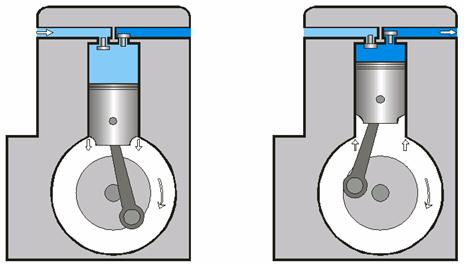 | Figure 1. Single-Stage Piston Compressor |
The dual-stage piston compressor shown in figure 2, when the working air from the atmosphere is received and sent by two compression stages, and between the air is cooled to remove excess heat created by friction from the piston [13].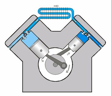 | Figure 2. Dual-stage piston Compressor |
The diaphragm compressor illustrated in figure 3, has the function similar to the reciprocating compressor, however, the atmospheric air does not contact with the mechanical parts of the piston, causing the generated compressed air have fewer impurities [14].The compressor straw, illustrated in figure 4 generates a centripetal force, promoting the displacement of the vanes, and a vacuum. This compressor has as main characteristic cause high air volume capaciwith low pressure [15].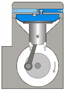 | Figure 3. Diaphragm Compressor |
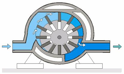 | Figure 4. Compressor Vane |
The screw compressor shown in figure 5, acts through the rotary movement of two screws, one concave and one convex, so that atmospheric air is brought into its interior. Its main features are: high performance, large flow, continuous pressure and the absence of oil [16].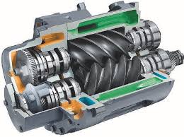 | Figure 5. Screw Compressor |
3.2. Air Reservoir
The air tank has the function of eliminating the oscillations in the pressure provided by the compressor and help reduce the compressed air temperature before the air dryer. Air tanks follow, in Brazil, the NR-13 standard. According to NR-13 items required in a compressed air reservoir are: relief valve, pressure gauge, inspection hatch, drain the condensate [17].
3.3. Treatment of Compressed Air
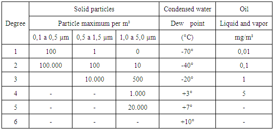
The quality of air used is the most important factor for the proper functioning of the filtration equipment. The compressed atmospheric air, has in its composition a variety of particles of impurities and humidity, after compression of the air, these particles added to the concentrate and oil particles in amounts which vary according to the type of compressor used. This mixture makes the air unfit for use without proper filtration. Each application has an ideal level of filtering, which should ensure the proper functioning of equipment to be used. Also, the better the filtration, better performance and higher reliability and possibilities to make the most of the life of the equipment, while minimizing interruptions for maintenance. Most of these interruptions are related to locking valves. Excess moisture also causes oxidation air pipe, generating more impurities in system [18]. Quality assurance should be considered for the design of a pneumatic system. The ISO8573-1 standard refers to the amount of impurities and contaminants provides a specific degree recommended for typical industrial applications, as shown in Table 1.Table 1. Number of Impurities Contaminants
 |
| |
|
The condensate separator filter that has the function to remove the condensed water from the air line must be installed on the spot with higher pressure and lower temperature, as far as possible from the compressor. Since the line filter has the function of removing oil, water and particulate matter through the filter element that allows the blocking fine particles is essential for all sorts of compressed air applications. The filter odor remover has the function of eliminating odors in the air outlet through an activated carbon element, applied in packaging processes and breathing systems for odor removal [19].Figure 6 illustrates the internal construction of the condensate eliminator filter.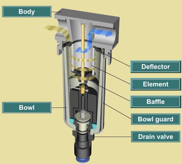 | Figure 6. Line Filter with Automatic Drain |
The compressed air lubrication no longer needs to be applied in modern pneumatic equipment, as they are already provided a pre lubrication throughout its service life. Non-lubricated systems have some advantages, such as hygiene, cleanliness and cost savings of lubrication equipment, thus providing a healthy and safe working environment. For cases that require lubrication, which has a lubricator provides a mixed oil mist to the air flow to reach the equipment. If the oil reaches devices that do not require lubrication it dissolves permanent grease nullifying their property, requiring, therefore, definitely lubrication [20].Figure 7 illustrates the internal line lubricator system.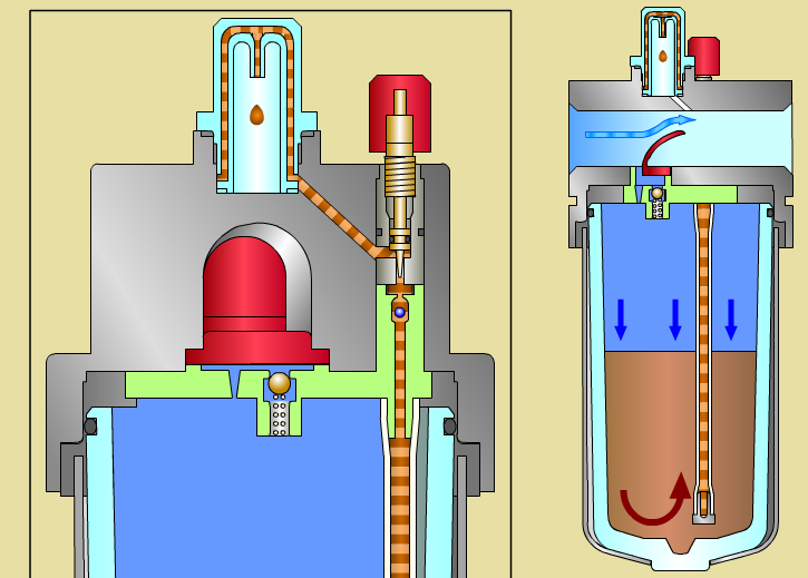 | Figure 7. Oilers pneumatic system |
The pressure regulator, as illustrated in figure 8, is an indispensable equipment for any application in which use compressed air as an energy source, their basic functions are smooth and stabilize the air pressure [20].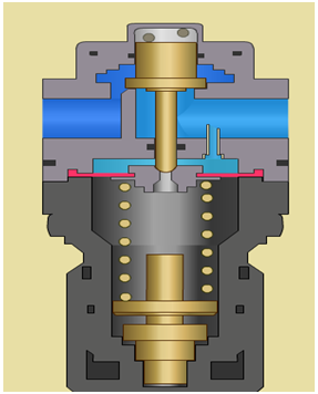 | Figure 8. Pressure Regulator |
The drain has the function of removing water and impurities from the compressed air network. In the past, the drains were actuated manually, but the lack of serious care problems entailed in pneumatic systems. Currently, automatic drains are used, as shown in figure 9, which are responsible for draining condensate from compressed air systems without the assistance of an operator. They are basically used two types of automatic drain: automatic drain for float and motorized automatic drain. 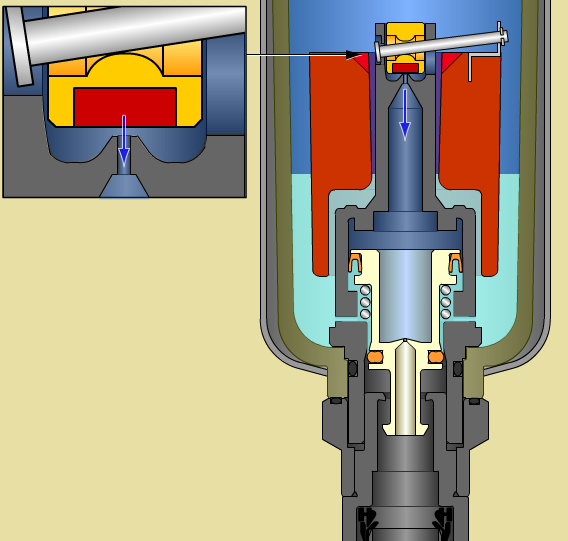 | Figure 9. Functional System automatic drain |
Automatic drain by float: an opening and closing valve is actuated by a float (float). When the drain tank is full, the float rises and allows the passage of water flow. Motorized automatic drain: electrical operation, similar to the operation of a clock when the axis completes the 360° turn, a pin triggers a poppet type valve which will release the passage of the condensate to flow [20].
4. Experiment Details
The case study was necessary to obtain confirmation of the research with the assembly of the practical test. A prototype was developed to demonstrate the practical data to the study of theoretical data.
4.1. Base Material
The polypropylene corresponds to a semicrystalline thermoplastic, low cost, using a common material used in various applications, with resistance characteristics and light weight, thus meeting the ergonomics standards.
4.2. Drawing/Pneumatic Scheme
The pneumatic diagram of the sealing prototype illustrated in figure 11 is operable to simulate the closure of the test tube and perform the leak test (Leak Test), thus ensuring the sealing of the part in process. It contains an entry for air to the compressor, thus dividing the required pressures for each of the pneumatic scheme using two pressure regulators filters to the sealing portion and leak test. The leaks are simulated by a regulatory flow after the switch, thus obtains the simulation with a certain leakage in l/m (liter/minute), the instantaneous measurement performed by the flow switch corresponds to the casting of the piece, and the pressure applied in the test is controlled by a pressure regulating valve, thereby limiting the required pressure as the material used because the resistance of the material. It contains two pneumatic actuators to seal the piece, ensuring the sealing of the two ends, after the test, pneumatic actuators return to normal position.The pneumatic prototype design was developed in order to simulate leaks in parts and adjust the pneumatic scheme developed. It was designed in SolidWorks software in 2D and 3D format, with dimensional for didactic use, using automation devices purchased through sponsorships and personally.Figure 10 illustrates the mechanical design of the prototype.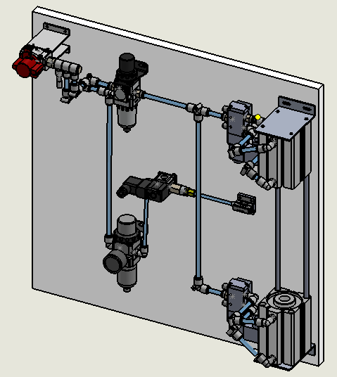 | Figure 10. Pneumatic Prototype Design |
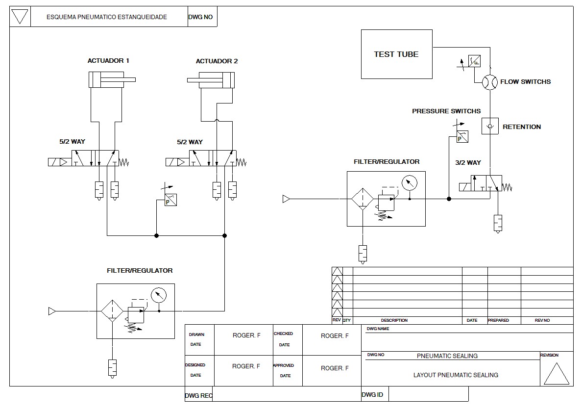 | Figure 11. Pneumatic Scheme |
4.3. Pressure Switch Prototype
The switch that was used in the prototype's manufacturer SMC Pneumatics ISE series. It has the function of monitoring the pressure by sending the data to the controller, thus obtaining the necessary feedback from the pressure according to the application. The switch contains two digital outputs and one analog, display (four) digits in red and green colors.
4.4. Flow Switches Prototype
The flow meter is used in the design of PFMV5 series SMC Pneumatics manufacturer and corresponds to a flow sensor with a short response time and which can be mounted in a small physical space. This equipment can be applied in a vacuum system leak or pressure lines and having the following characteristics:Ÿ 5ms response time;Ÿ Maximum pressure of 500 kPa;Ÿ Repeatability of ± 2%;Ÿ Measurement of maximum 1 l/m.The principle of operation of the switch used in the prototype corresponds to the variation of temperature according to the movement of air. The flow switch has four internal resistors Ra, Ru, Rh and Rd The resistor Ra has the function of measuring the ambient temperature. Ru has the function of measuring the temperature; Rh perform symmetric measurement between resistors as the air movement; Rd and the resistance measured at low temperature [21].Figure 12 shows two examples, one with the flow and without moving the other with the moving stream.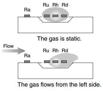 | Figure 12. The Flow of Air Inside the Switch |
The output curve shown in figure 13 corresponds to a non-linear response, stating the output voltage from the instantaneous flow.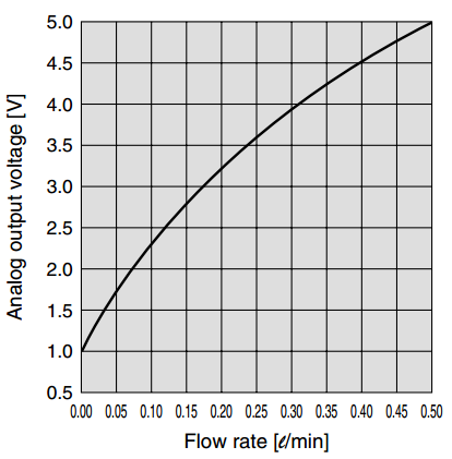 | Figure 13. Instantaneous Flow & Analog output |
4.5. Flow Regulator
The prototype flow regulator manufactured by SMC Pneumatics company AS series, has the function of controlling the flow of air in the advance and retreat of the actuators and also to simulate the test of the leak. There are two types used in flow regulation:The inlet flow regulators used on double acting actuators, which cause movements "in leaps." These leaps are related to the type of regulation, because there is no restriction to the output flow. Thus, the movement is compromised, since the output throughput is larger than the entrance, a counter pressure is generated for a uniform motion is guaranteed.The output flow regulation ensures the pressure, because it restricts the amount of air coming out, creating a sort of "air mattress" in the actuator. You can also adjust the output to the valve exhaust, using a silencer with flow regulation, this application reduces the cost of the project, it employs two products in one body, moreover, brings speed control closer to the operator, because the actuators are often less accessible sites of the valves.
4.6. Filter Pressure Regulator
The prototype of the throttle filter, also manufactured by SMC Pneumatics AW series, has the function of filtering the air removing impurities and controlling the pressure by the need of the application, the prototype was used two regulators filters, the first filter regulator was used in order to control the pressure of the actuators, and the second filter regulator was used in order to control the test pressure.
4.7. Pneumatic Actuator
The actuators can be classified in the following ways: linear cylinders; compact; sliding or rotating tables; and actuators claw type (tweezers). As its internal construction its operation can be single or double action.The pneumatic actuator prototype, manufactured by AIRTAC, the compact design has the main function of sealing the holes in the test tube, thus blocking the air passage. At the time of advance and retreat of the actuator devices attached to the rod with nit rile have the purpose of making the seal bore. Actuators are the elements responsible for handling or moving the pieces to be worked.For the dimensioning of the actuators the following formulas are used:Theoretical Force Advance: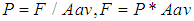 P = Operating pressure (kgf / cm²)F = Force (kgf)Aav = Advance Area actuator = π.d² / 4 where: d= piston diameterForce Return Theory:
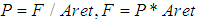 P = Operating pressure (kgf / cm²)F = Force (kgf)Aret = Return Area actuator = π. (D²-d²) / 4 where:D = piston diameterd = rod diameterWhen sizing an actuator must always consider that we have the forces of resistance to its motion to be considered and subtracted from the theoretical force at the time of the final design. In all actuators have friction on their sliding parts. This friction causes a counter force to the movement, making the effective force always less performance than the theoretical strength. The internal friction of an actuator can vary according to the type of gasket, mounting position, load to be moved, among others. Therefore, the effective force of an actuator can be set only after a verification application.The consumption of air is an important factor in the installation of an actuator, based on it we will know the ideal valve to be used to feed it. If the valve used is not able to provide the required flow for the use, operation of the actuator will be compromised, to calculate the flow consumed by an actuator duty cycle will have to check the instantaneous flow rate and avoid a significant error in the valve sizing.Instantaneous Flow Actuator:
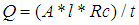 t = maximum time for execution of the work (s)A = actuator piston area to be filled (mm²)l = actuator stroke (mm)Rc = Compression RatioRc = (gauge pressure + 1,033) / 1,033
4.8. Shutoff Valve
The prototype of the shutoff valve, manufactured by SMC Pneumatics VHS series, serves to block and allow the passage of air. It has been installed in the prototype pressure input.
4.9. Test Tube
The test piece was machined to size for testing and to obtain results as instruments acquired with the same dimensional hole of the seal. Its composition was made of aluminium. Therefore, the prototype simulation corresponds to the leak in the flow regulating part and not in the test.
4.10. Directional Valve
The directional valve prototype, manufactured by AIRTAC, has the function of releasing and blocking the passage of compressed air through an electrical signal, the valve is coupled to a coil which receives the voltage signal.
4.11. Electrical Scheme of the Drive Relay Board
The wiring diagram of the drive plate is composed of 5V relays, diodes, capacitors, voltage regulators, resistors, LED's and terminals. Designed with maximum load current of 10A, sufficient for actuating the pneumatic valves, the 5V applied voltage regulator has the function of entering a higher voltage and limit at 5V, so the power dissipated in the regulator presents heat and start heating the outside of the regulator. The capacitors have the purpose of carrying out the stabilization of the stresses acting as a filter, thus eliminating external noise. The diodes used have the function of protecting the relay, it makes a reverse link in parallel with the relay coil and protects against reverse current, no reverse conducting current. The LEDs used inform the status of the drive each relay. And the resistors have the function of obtaining the voltage drop to feed the LEDs with the required voltage component.
4.12. Electrical Scheme of the Photo Coupler Board
The wiring diagram of the photo coupler plate was developed with the function of being the intermediary and protection between the controller and the drive board relays. The circuit consists of photo couplers, resistors, transistors and terminals. The photo coupler has the function to emit a light by physical means of LED. At the moment it receives the light, drives the base of transistor internal releasing the passage of current through the emitter of transistor with the purpose of driving a high power load at low voltage.The resistors used have the function to perform the falls stresses that each component needs, and transistors, to block and release current flow as the circuit state change.
4.13. Electric Prototype Assembly
The electrical assembly, shown in figure 14, was held in bench with all the tools necessary for its implementation, through the junction of electrical circuits developed as descriptions on items 4.9 and 4.10 of the same section.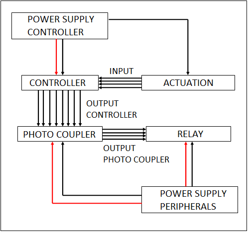 | Figure 14. Connection of electrical circuits developed |
Electronic circuits were developed in simulators before its application, designed for printed circuit boards, getting a compact electronic assembly and practical for electrical assembly. For the fixation of the printed circuits have been used fixatives and fasteners made from two independent parts which join tissue. At the junction between the developed circuits were used connectors to facilitate possible maintenance.
4.14. Mechanical Assembly of the Prototype
The mechanical assembly, shown in figure 15, was held in bench with all the tools necessary for their achievement, as mechanical design illustrated in figure 11, with the development of all the supports and fixing each pneumatic and electrical item, and more importantly, the accuracy in the mounting of actuators to achieve the best possible sealing part test as mechanical design project.Description of the images below:A) By sticking to the command box;B) Welding wires of the control box;C) Measuring the actuator bracket;D, E) finished Mechanical design.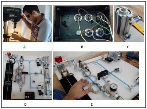 | Figure 15. Photos of mechanical prototype assembly |
4.15. Controller Programming in the Prototype
The schedule was carried out in Arduino platform through the C language, using the LiquidCrystal.h library, used for the operation of the LCD device.The control system was conducted in closed loop, thus obtaining feedback from the process to control variable, also used to avoid disruptions in the measurement variable and eliminate any disturbance that may affect the operation of the control system [22].The figure 16 shows the control closed loop system.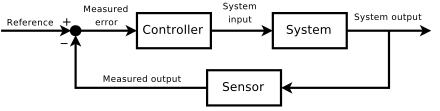 | Figure 16. Control closed-loop system |
4.16. Tests and Results
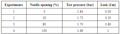
In the final prototype testing we found that the work of the case study obtained positive results expected by the study bibliography. Each test was simulated with an air leak through a regulatory flow can be adjusted leakage by opening the needle regulator itself, so after the tests it was possible to analyze what actually measuring instantaneous flow through the switch has time faster response and get the leak in the vicinity of the actual value in liters / minute, also could be noted that there are variations in reading the full scale of the reason the switch and drive limitations A/D controller.Table 2 can view the results of the tests.Table 2. Results of leak testing
 |
| |
|
The figure 17 shows the first test carried out with the fully sealed system without leakage. Therefore, proves that with the system sealed, the test pressure will be higher relative pressure with the system leak, the reason there is no air leakage.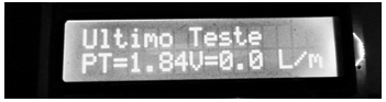 | Figure 17. Experiment 01 |
The figure 18 shows the second test performed with the needle of the flow regulating the position of 30% system of opening and partial leakage. Note that the test pressure is lower than the first behavior pattern illustrated in figure 17.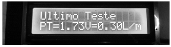 | Figure 18. Experiment 02 |
The figure 19 shows the third test performed with needle flow regulating the position of 80% system of opening and partial leakage. It is found that the test pressure has lower performance than the first and second test performed, illustrated in figure 17 and figure 18.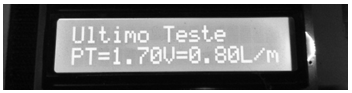 | Figure 19. Experiment 03 |
The figure 20 illustrates the last test performed with needle flow regulating the position of 100% opening and the total system leakage. It is observed that the test pressure has the lowest performance among the tests carried out by reason of the compressed air flow is the highest among the tests.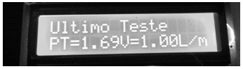 | Figure 20. Experiment 04 |
4.17. Conclusions
There is great difficulty in finding a perfect flow measurement system, because it is often affected by many factors related to the environment, the form and the application technique and the influence of his own greatness. Therefore, when developing system and a mechanical sealing device is required to study the application to perform perfect control and appropriate peripherals for operating the project. The prototype performed the simulation of air leakage of a particular end product, with the theoretical comparative study, obtaining similar results to the theoretical. This work demonstrated that the flow meters represent a necessary evolution for industrial processes, among them are the tightness of meters that are essential for the final quality of the product manufactured in the industry.
References
| [1] | FOX, R. W., McDonald, A. T., & Pritchard, P. J. (2006). Introduction to fluid mechanics (6 ed., Vol. 1). Rio de Janeiro: LTC. |
| [2] | HOLMAN, J. P. (2001). Experimental methods for engineers (7 ed., Vol. 1). New York: Mc Graw-Hill. |
| [3] | Delmée, G. J. (2003). Manual de medição de vazão (3 ed., Vol. 1). São Paulo: blucher. |
| [4] | HASHIMOTO, Ana Paula Maia Braga; CABRAL, Samantha Grimm; VALLE, Vilmar. Teste de estanqueidade em sistema de combustível de aeronaves utilizando gás hélio. |
| [5] | ROSÁRIO, J. M. (2005). PRINCÍPIOS DE MECATRONICA. PEARSON. |
| [6] | MCROBERTS, M. (2011). ARDUINO BÁSICO (1 ed.). NOVATEC. |
| [7] | Muller, Rolf (1998). Pneumatics: theory and applications. |
| [8] | THOMAZINI, Daniel; ALBUQUERQUE, Pedro Urbano Braga de. Sensores industriais: fundamentos e aplicações. São Paulo, v. 3, p. 32, 2005. |
| [9] | ANASTASI, Giuseppe et al. Performance measurements of motes sensor networks. In: Proceedings of the 7th ACM international symposium on Modeling, analysis and simulation of wireless and mobile systems. ACM, 2004. p. 174-181. |
| [10] | CEWERS, Göran. Directional valve. U.S. Patent n. 6,536,433, 25 mar. 2003. |
| [11] | NOVAIS, J. (1995). AR COMPRIMIDO INDUSTRIAL. |
| [12] | SILVA, N. F. (2009). Compressores Alternativos Industriais - Teoria e Prática. Rio de Janeiro, Brasil: Interciência. |
| [13] | Kaido, Peter F., and Michael J. Dormer. "Compressor for single or multi-stage operation." U.S. Patent No. 5,577,390. 26 Nov. 1996. |
| [14] | Bramstedt, David, and Roy J. Rozek. "Diaphragm compressor." U.S. Patent No. 4,842,498. 27 Jun. 1989. |
| [15] | Huang, Yuan Mao, and Sheng-An Yang. "A measurement method for air pressures in compressor vane segments." Measurement 41.8 (2008): 835-841. |
| [16] | Stošić, N. "On gearing of helical screw compressor rotors." Proceedings of the Institution of Mechanical Engineers, Part C: Journal of Mechanical Engineering Science 212.7 (1998): 587-594. |
| [17] | MINISTERIO DO TRABALHO. (2006). Manual técnico de caldeiras e vasos de pressão - NR-13. BRASÍLIA: FUNDALC. |
| [18] | Behnke, Albert R. "Effects of High Pressures: Prevention and Treatment of Compressed Air Illnes." Medical Clinics of North America 26.4 (1942): 1213-1237. |
| [19] | Childs, Peter RN. "Pneumatics and Hydraulics-Chapter 18." |
| [20] | STEWART, H. L. (2013). PNEUMÁTICA & HIDRÁULICA. HEMUS. |
| [21] | SMC-PFMV5. “https://www.smcworld.com/upfiles/manual/e/PFMV5eng.pdf”. |
| [22] | OGATA, K. (2010). Engenharia de controle moderno (4 ed, Vol. 1). PEARSON. |

 Abstract
 Reference
 Full-Text PDF
 Full-text HTML