-
Paper Information
- Next Paper
- Previous Paper
- Paper Submission
-
Journal Information
- About This Journal
- Editorial Board
- Current Issue
- Archive
- Author Guidelines
- Contact Us
Journal of Mechanical Engineering and Automation
p-ISSN: 2163-2405 e-ISSN: 2163-2413
2016; 6(5): 128-138
doi:10.5923/j.jmea.20160605.05

Transient Heat Transfer and Energy Balance Model for Hydrodynamic Torque Converters while Operating at Extreme Speed Ratio
 Abstract
 Reference
 Full-Text PDF
 Full-text HTML
Darrell Robinette, Jason Blough
Dep’t Mechanical Engineering-Engineering Mechanics, Michigan Technological University, Houghton, MI, USA
Correspondence to: Darrell Robinette, Dep’t Mechanical Engineering-Engineering Mechanics, Michigan Technological University, Houghton, MI, USA.
| Email: |  |
Copyright © 2016 Scientific & Academic Publishing. All Rights Reserved.
This work is licensed under the Creative Commons Attribution International License (CC BY).
http://creativecommons.org/licenses/by/4.0/

This investigation details the development of a simple transient model to predict the bulk toroidal flow fluid temperature of the automotive torque converter based upon an energy balance and the derivation of an overall convective heat transfer correlation for the entire turbomachine. Data collected on a torque converter specific dynamometer setup is used to derive a Nusselt correlation for overall convective heat transfer from the shell using measured parameters. Dimensional analysis applied to three torque converters of nearly exact geometric similitude was used to show the applicability of the correlation to prediction of the overall external convective heat transfer mechanism. Discussion is focused on operation at low speed ratios for varying lengths of time. This particular condition represents the worst-case scenario for torque converter operating efficiency and heat rejection. It was found that the external heat rejection from the torque converter shell surface is a function of the rotational Reynolds number and proportional to the characteristic dimensionless performance number unit input speed. The model is shown to trend with temperature measurements made at the external shell of the torque converter over a variety of zero speed ratio transient maneuvers. Overall, the first order, linear differential equation model and Nusselt correlation for overall heat transfer are a first step in developing an adequate tool for use in future torque converter designs predicated on scalability of the turbomachines performance quantified through dimensionless numbers.
Keywords: Torque converter, Transient heat transfer, Nusselt correlation, Dimensional analysis
Cite this paper: Darrell Robinette, Jason Blough, Transient Heat Transfer and Energy Balance Model for Hydrodynamic Torque Converters while Operating at Extreme Speed Ratio, Journal of Mechanical Engineering and Automation, Vol. 6 No. 5, 2016, pp. 128-138. doi: 10.5923/j.jmea.20160605.05.
Article Outline
1. Introduction
- The torque converter is a particular class of turbomachine used in a wide variety of power transfer applications to couple the prime mover to the gear system of an automatic transmission. Torque converters can be found in on or off highway powertrain applications and is most commonly utilized in automatic transmissions to enhance the initial acceleration performance of the vehicle. It is also a means of improving system durability since the torque converter has superior cooling characteristics and does not experience wear like that of a friction launch clutch. The modern three-element torque converter consists of a closed loop torus containing a mixed flow pump, a mixed flow turbine and an axial flow stator. The device is required to operate over a range of speed ratios from zero to values greater than one. Speed ratio is defined as the rotation of turbine speed divided by pump speed. At zero speed ratio, maximum torque multiplication is achieved, while maximum efficiency occurs at speed ratios between 0.85 and 0.95 depending on the details of the design. As a result, the flow field is three-dimensional within the torus, producing secondary flow structures and the potential for two-phase mixture, e.g. cavitation, depending on the severity of the specific operating condition. A detailed description of the torque converter and previous experimental or numerical studies can be found in [1-3] for example.Selection of a torque converter design is performed numerically to match the torque and speed characteristics of the prime mover to a particular powertrain application to balance acceleration and efficiency for the range of operation conditions expected. The geometry of the torus and individual elements is developed through iterative CFD and other numerical methods, and then validated through physical hardware testing on a dynamometer to achieve specific performance targets, see [4-8]. To meet physical packaging constraints or to minimize the occurrence of performance inhibiting toroidal flow structures such as stalled or reversed flow and large volume cavitation, further refinement of the torus dimensions, pump and turbine blade angles and stator blade geometry may be undertaken. Additionally, the working conditions of the hydraulic fluid imposed upon the torque converter pressure vessel can be calibrated to suppress cavitation or create sufficient through flow cooling to maintain adequate toroidal flow operating temperatures. In automotive powertrain applications, the mega trend is towards increasingly power dense prime movers with greater torque availability at lower operating speeds due to turbocharging. Simultaneously, the dimensions of the torque converter torus are being significantly reduced to accommodate increased gear and clutch content of the automatic transmission to achieve 8, 9, 10 or more forward fixed gear ratios. Additionally, more torus space is being allocated for the lockup clutch damper to bypass the hydrodynamic circuit to further reduce fuel consumption once the vehicle has launched, see Figure 1. The combination of these two design trends results in greater demands on the turbomachine, particularly for extended operation at extreme speed ratios and elevated levels of torque transfer. The purpose of this investigation is to develop a first principal based model validated with experimental data that can predict the internal toroidal flow temperature of the torque converter. The method presented is based upon that reported by [9] for powertrain cooling and protection strategy based upon a predicted temperature internal to the torque converter. Predictions of these temperatures can be critical in determining required cooling capacity, establishing operating limitations for component durability, preventing cavitation and preservation of oil quality from excessive thermal cycling.
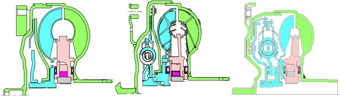 | Figure 1. Cross-sections of typical three element, automotive torque converters showing typical design trend over past 20 years, from left to right, oldest to newest |
2. Torque Converter Fundamentals
- The principals of torque converter operation and details of flow theory are contained in a number of sources found in the literature, [1, 4-8 and 10-14], for example. A brief discussion is provided here for reference and continuity of the material contained in this paper.
2.1. Performance Characteristics
- Torque converter performance is typically defined by dimensionless or semi-dimensionless quantities to match the turbomachine to specific applications are summarized in Equations 1 through 3. The quantities of torque ratio, TR, output (turbine) to input (engine or pump) torques and K-factor, K, input speed to square root of input torque are plotted versus speed ratio, SR, output to input speeds and forms the mainstay of matching torque converter – prime mover, see Figure 2.
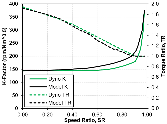 | Figure 2. Correlation of one-dimensional flow theory model with measured dynamometer data |
 | (1) |
 | (2) |
 | (3) |
 , with the addition of diameter, D, to the 5/2 power and square root of the density, ρ, of the operating fluid,
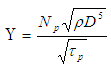 | (4) |
2.2. One-Dimensional Flow Theory
- A significant amount detailed research, both analytical and experimental, has been performed on torque converters, [4-8 and 10-14]. The fundamental laws of fluid mechanics and thermodynamics can be applied to create a one-dimensional flow model capable of useful predictions. The principles of conservation of angular momentum and energy for a control volume, CV, encompassing the fluid and bladed surfaces of the turbomachine elements are used to the define the model as given by Equations 5 and 6, though a thorough description is outside of scope for this paper and is readily available in the literature, see [10-14].
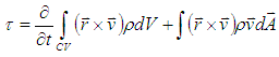 | (5) |
 | (6) |
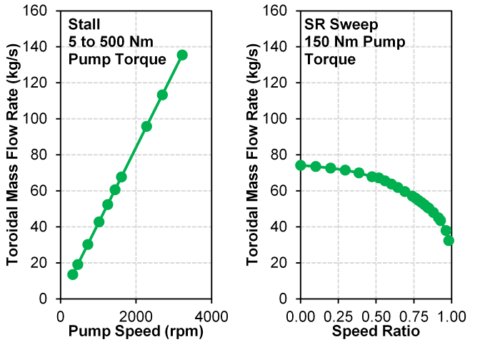 | Figure 3. Toroidal mass flow rate as a function of pump torque at stall and speed ratio for a fixed pump torque |
2.3. Energy Balance
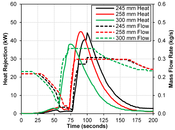
- An energy balance for the torque converter operating with or without the lockup clutch applied is shown in Figure 4. Shaft work input from the prime mover at the cover and pump (green) is converted to useful shaft work through the torus fluid and extracted in the turbine and lockup clutch damper (blue) assembly and then transmitted to the automatic transmission via the turbine shaft. The remainder of the energy not converted to useful shaft work is rejected as heat through two principal pathways. Cooling through flow,
 is supplied to the torque converter from the automatic transmissions high pressure oil supply which enters through the turbine shaft and mixes with the torus flow and exhausts back to the sump via passages between stator and pump shafts. Energy is also dissipated as heat from the torus to the external shell via forced convection from torus to shell,
  and shell to air,
  as well as conduction through the shell. The overall heat transfer mechanism from the external surface can be difficult to measure or quantify using traditional methods and will be a focus of discussion in the paper.
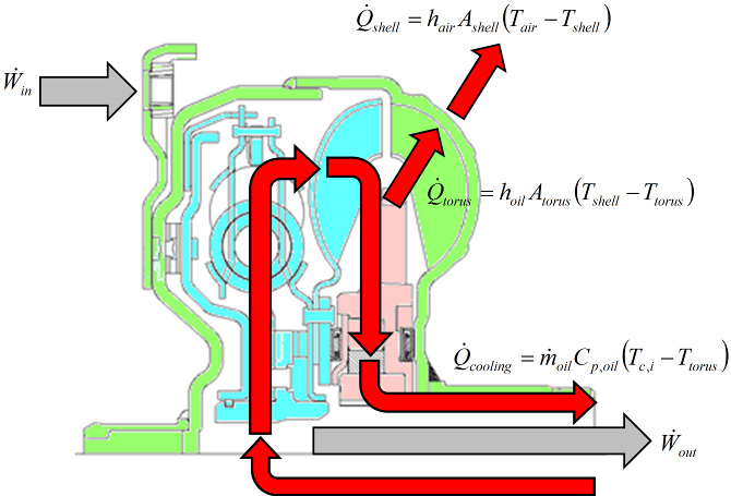 | Figure 4. Energy balance across a three torque converter with lockup clutch and cooling through flow circuit |
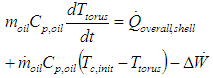
 , as seen in Equation 7. It should be noted that for this model, it is assumed that torus temperature is equivalent to the exhaust or outlet temperature from the torque converter.
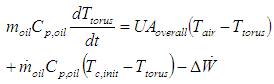 | (7) |
 and
and  in additional to conduction through the shell can be combined into an overall heat transfer term,
  given by,
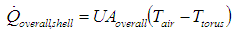 | (8) |
 | (9) |
 and
and  are equal to the following,
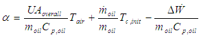 | (10) |
 | (11) |
 , to be equal to the cooling through flow inlet temperature,
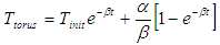
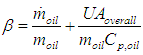
  which is assumed to be time invariant. A simplification can be made to Equation (9) if the amount of heat energy rejected through the external surface is assumed a known quantity,
 | (12) |
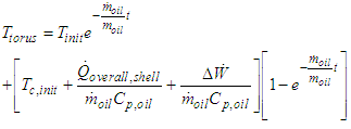 | (13) |
3. Experimental Setup
- A torque converter specific dynamometer test cell, Figure 5, was used to test three torque converters of nearly exact geometric scaling, see Figure 6, at stall. The testing was originally performed to determine the appropriateness of applying the dimensional analysis to developing a prediction tool for incipient cavitation in torque converters using a nearfield acoustical technique, see [8]. The dynamometer data collected during this testing can be further utilized to develop a model to predict torus temperatures during transient, high input power maneuvers when operating at low overall efficiency. The dynamometer was setup for the stall condition, zero output speed, only and all three torque converters were painted flat black to create the same radiation surface emissivity and to enable a more suitable infrared surface temperature measurement. The details of this measurement setup can be seen in Figure 5, along with nearfield microphones to detect cavitation enclosed in a nitrile cover to prevent oil contamination. The torque converters tested were 245, 258 and 300 mm diameters as measured at the pump outside diameter and had a stall unit input speed rating of 140, corresponding to K-factors of 163, 146 and 101, respectively. Figure 7 contains performance data, K-factor and torque ratio as a function of speed ratio, from dynamometer testing for the three torque converters tested in this investigation. The near perfect geometric scaling of all three torque converters results in the value of the dimensionless unit input speed to be equivalent across the range of speed ratios tested as noted in Figure 8.
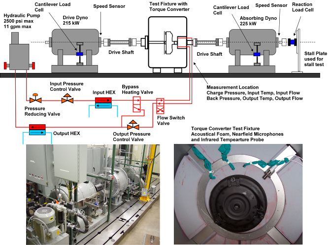 | Figure 5. Torque converter specific dynamometer test cell and test fixture instrumentation |
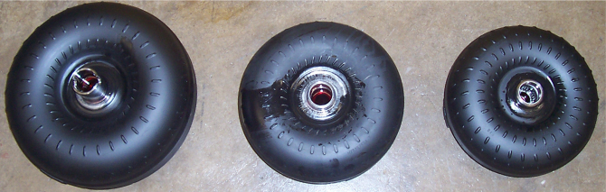 | Figure 6. Geometrically scaled torque converters tested with U = 140, from left to right, 300 mm, 258 mm and 245 mm pump diameters |
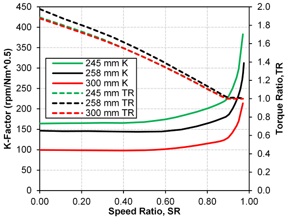 | Figure 7. K-factor and torque ratio vs. speed ratio for the three torque converters tested for this investigation |
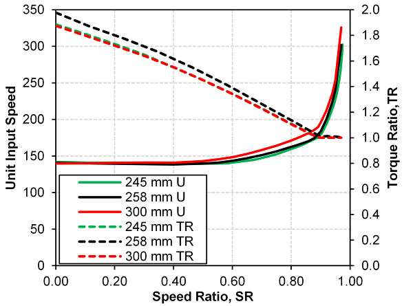 | Figure 8. Unit input speed and torque ratio vs. speed ratio for the three torque converters tested for this investigation |
4. Results
4.1. Stall Speed Sweeps
- A common set of stall speed sweep tests were performed for this investigation, ramping pump speed of the torque converter from 100 r/min to maximum speed ranging between 2500 to 2900 r/min depending on the design being tested. Pump speed was swept at four ramp rates of 40, 100, 200 and 500 r/min/s. These ramp rates were selected to span those realized during vehicle operation. The worst case condition is 40 r/min/s for internal heat build-up in the torus fluid to a ramp rate of 500 r/min/s more typical of operation in a vehicle powertrain. Once the peak pump speed was achieved, pump speed was ramped down to a 100 r/min at a ramp rate of -300 r/min/s. Once pump speed reached 100 r/min, an extended cool down period was allowed for torus fluid temperature to stabilize to that of the oil supply. The stall speed sweep test procedure and measurements of cooling through flow rate and temperatures at the inlet, outlet and surface of the torque converter shell is summarized in Figure 9 for a sweep rate of 40 r/min/s. Figure 10 contains the stall speed sweep temperature data for all sweep rates for the 258 mm torque converter showing only the ramp up in speed portion of the test.
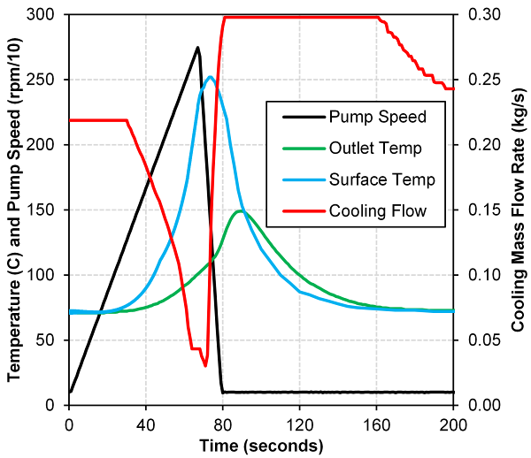 | Figure 9. 258 mm torque converter, cooling mass flow rate and operating temperatures during a 40 r/min/s stall speed sweep and subsequent cool down period |
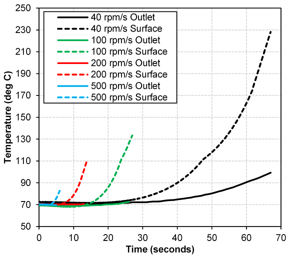 | Figure 10. 258 mm torque converter surface and outlet temperatures during various stall speed sweep tests |
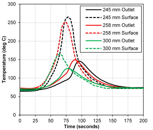 | Figure 11. Effect of torque converter size on surface and outlet temperatures at a 40 r/min/s stall speed sweep rate and cooling cycle |
4.2. Cooling Flow Heat Transfer
- The cooling through flow to the torque converter torus acts as a mixing flow heat exchanger. Cooler automatic transmission oil enters the torus through flow passages in the turbine shaft and mixes with warmer torus fluid, causing displacement of warmer fluid to exit through passages in the stator shaft. This process is roughly depicted in Figure 4 and can be approximated as a heat exchanger with the amount of heat transferred determined from the following,
 | (14) |
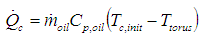
 | Figure 12. Heat rejection from cooling through flow for 245 mm, 258 mm and 300 mm torque converters during 40 r/min/s stall speed sweep and cool down cycle |
4.3. Overall External Heat Transfer Coefficient – Conventional Approach
- This section will detail calculations of heat transfer coefficients and rates related to determining the amount of heat rejected through the external surface of the torque converter. The rotational Reynolds number, Equation 15, was used in this investigation to characterize the turbomachines operating flow regime for both internal and external flows. For internal flow, the critical Reynolds number for transition to turbulent flow is 2500 while for external flow the transition point was taken to be 250000.
 | (15) |
4.3.1. Internal Convection
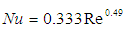
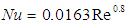
- The heat transfer coefficient for forced convection from the torus flow was determined using the Nusselt correlations in Equations 16 and 17 for laminar and turbulent flow, respectively, approximating the individual blade passages within the torque converter elements as rectangular passages.
 | (16) |
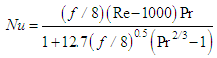 | (17) |
4.3.2. External Convection
- External heat transfer coefficients were sought out from multiple sources, namely flow over a flat plate, [15], and rotating disks or cylinders in air, [16,-18]. Both approaches yielded similar heat transfer coefficients for the given geometry and boundary conditions. However, those derived specifically for rotating disks in air were selected due to the closer approximation to the rotating torque converter in the test fixture. The Nusselt correlations utilized are from testing conducted by [17] and are as follows,
 | (18) |
 | (19) |
4.3.3. Overall Heat Transfer Coefficient
- The internal and external heat transfer coefficients found using available Nusselt relationships were combined with the conduction coefficient through the torque converter shell to define an overall heat transfer coefficient as described in many heat transfer textbooks, [19] for example. The limiting factor for the overall heat transfer coefficient becomes the external forced convection with a heat transfer coefficient an order of magnitude less than that of internal convection for the torus to the shell. The result is minimal heat rejection through the external shell to the air, which during a slow stall speed sweep in which power input is relatively high throughout the majority of the stall maneuver will produce extreme torus temperatures. An example prediction of torus flow temperature using Equation 9 and an overall heat transfer coefficient from Equations 16 to 19 for a 258 mm torque converter is shown in Figure 13. Also included in Figure 13 are measured surface and outlet temperatures during the 40 r/min/s stall speed sweep. As expected with the minimal overall heat transfer coefficient for external surface heat rejection, torus temperature is predicted to peak at an unreasonably value of 900°C. It was concluded that the available Nusselt relationships cannot be applied to this particular situation with good confidence and that an alternative Nusselt relationship must be derived.
 | Figure 13. Torus fluid temperature prediction using available Nusselt relationships and Equation 9 for 258 mm, 140 unit input speed torque converter during 40 r/min/s stall speed sweep and cooling cycle |
4.4. Overall External Heat Transfer Coefficient – Derived Nusselt Correlation
- A Nusselt correlation unique to this particular heat transfer aspect for torque converter applications is derived to predict the external heat transfer mechanism more appropriately. Similar approaches to predict heat transfer have been defined by [20, 21] as applied to automotive turbochargers and torque converter lockup clutches, respectively. The heat energy rejected through the torque converter external surface can be reduced to the relationship of Equation 20 assuming the heat energy rejected is proportional to the input power by the scaling factor,

 | (20) |
 should be a function of the torque converter design, size and performance attributes, such as unit input speed and operating fluid properties. For this investigation, it was found that scaling the input power by Equation 21 resulted in a universal Nusselt correlation, see Equation 22, for the three diameter torque converters tested.
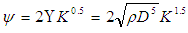 | (21) |
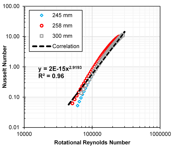 | Figure 14. Derived Nusselt correlation for overall heat transfer coefficient from torque converters of constant unit input speed and geometric scaling |
4.5. Model Correlation and Torus Fluid Prediction
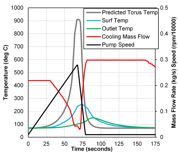
- The derived Nusselt correlation of Equation 22 was used as an input for the solution of the differential equation describing the energy balance of the torque converter, Equations 12 and 13, at stall to predict the torus fluid temperature. The models prediction capability is shown for two examples, the results of which are contained in Figures 15 and 16. In the first example, the 258 mm torque converter is performing a 40 r/min/s stall speed sweep and cool down cycle. The predicted torus temperature leads the surface temperature measurement in very close association, while outlet temperature lags predicted torus temperature as cooling flow drops during high stall speeds then surges once pump speed drops. It can be noted that torus temperature drops rapidly once cooling mass flow rate increases, and sufficient cooling flow mixes with the hot torus fluid, being fully replaced within a period of approximately 15 seconds.
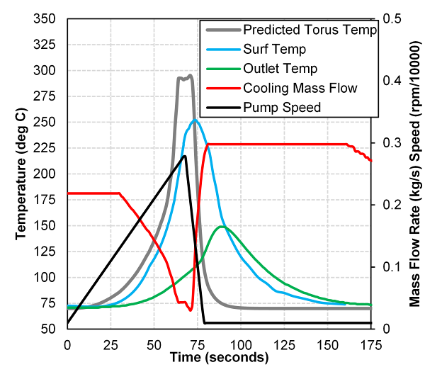 | Figure 15. Torus fluid temperature prediction using derived Nusselt relationship and Equation 13 for 258 mm torque converter during a 40 r/min/s stall speed sweep and cool down period overlaid with surface and outlet temperatures |
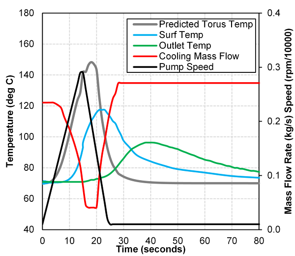 | Figure 16. Torus fluid temperature prediction using derived Nusselt relationship and Equation 13 for 245 mm torque converter during a 200 r/min/s stall speed sweep and cool down period overlaid with surface and outlet temperatures |
4.6. Future Developments
- The transient model presented in this investigation was derived focusing on the stall operating condition, which is an extreme condition, but most severe for thermal loading of the torus fluid. Future testing should focus on the development and validation of the model for transient or steady state speed ration operation between 0 and 1. This is will require potential further development of the derived Nusselt relationship which may take the following functional relationship,
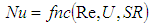 | (23) |
5. Conclusions
- A first order, linear differential equation model based upon an energy balance of the torque converter was developed to predict internal torus fluid temperatures at the extreme stall operating condition, zero speed ratio. A Nusselt correlation was derived specific to the overall turbomachine for external heat transfer as it was found that conventional relationships were inadequate in accurate prediction. The heat rejected from the torque converter external surface was found to be proportionally scaled by the two times the square root of the torque converters diameter to the power of 5 and operating fluid density and a semi-dimensionless attribute, K-factor, raised to the power of 1.5. This relationship was shown to collapse the Nusselt relationship to a single function of the rotation Reynolds number for three torque converters of geometric similitude. Prediction of torus temperatures trended with measured temperature data acquired at the shell surface and outlet flow during dynamometer testing. The next steps in this research would be to develop fully the Nusselt relationship to include speed ratios other than stall to enhance its prediction capability for all operating conditions the torque converter experiences during typical powertrain maneuvers in vehicle applications.
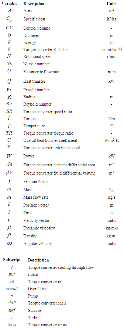
Nomenclature