-
Paper Information
- Next Paper
- Paper Submission
-
Journal Information
- About This Journal
- Editorial Board
- Current Issue
- Archive
- Author Guidelines
- Contact Us
Journal of Mechanical Engineering and Automation
p-ISSN: 2163-2405 e-ISSN: 2163-2413
2016; 6(5): 117-127
doi:10.5923/j.jmea.20160605.04

Damage Assessment of a Large-Scale Hybrid Composite Wind Turbine Blade
 Abstract
 Reference
 Full-Text PDF
 Full-text HTML
Norimichi Nanami1, Ozden O. Ochoa2
1Department of Mechanical Engineering, Nihon University, Tokyo, Japan
2Department of Mechanical Engineering, Texas A&M University, College Station, USA
Correspondence to: Norimichi Nanami, Department of Mechanical Engineering, Nihon University, Tokyo, Japan.
| Email: |  |
Copyright © 2016 Scientific & Academic Publishing. All Rights Reserved.
This work is licensed under the Creative Commons Attribution International License (CC BY).
http://creativecommons.org/licenses/by/4.0/

Wind energy is realistically poised to meet the demands of an increasing world population with economic viability. The size of the horizontal-axis wind turbines (HAWT) has increased rapidly to match this higher energy demand, leading to an exponential increase in the blade weight. A credible approach to reduce weight is to utilize hybrid composites such as carbon and glass fiber (CF/GF) reinforced polymers to improve specific stiffness/strength and damage tolerance. Herein, we present our design and damage assessment study of a large-scale hybrid composite HAWT blade under static and dynamic conditions representative of aerodynamic and bird impact loads. Static analyses identified core damage and local wrinkling as primary modes, and the blade configuration provided excellent damage tolerance below wind speed of 8.72 m/s. The bird impact simulations at the blade tip revealed that the reinforcement architecture and geometry successfully survived the direct impact event without incurring any damage in the composites. The oblique impact led to local matrix tensile damage in the skin and the core damage at the impact site without any penetration.
Keywords: Coupled Eulerian-Lagrangian analysis, Damage initiation and evolution, Bird strike
Cite this paper: Norimichi Nanami, Ozden O. Ochoa, Damage Assessment of a Large-Scale Hybrid Composite Wind Turbine Blade, Journal of Mechanical Engineering and Automation, Vol. 6 No. 5, 2016, pp. 117-127. doi: 10.5923/j.jmea.20160605.04.
Article Outline
1. Introduction
- Wind energy is one of the most promising and mature alternatives to meet the energy needs of economic growth and population increase. It is capable of providing 72 TW (TW = 1012 W) of electric power, which is approximately four times the world energy consumption in 2012 [1, 2]. Thus, wind energy market has grown rapidly in the last couple of decades, boosting up the size of wind turbines to generate higher power output [3]. Mostly, a horizontal-axis wind turbine (HAWT) with propeller type blades is utilized in a large-scale wind power system, and its configuration as an upwind land-based construction is schematically depicted in Figure 1. The joining concept, internal structure, and damage assessment of the 80 m wind turbine blade has been studied in detail and reported by Nanami [4-6].
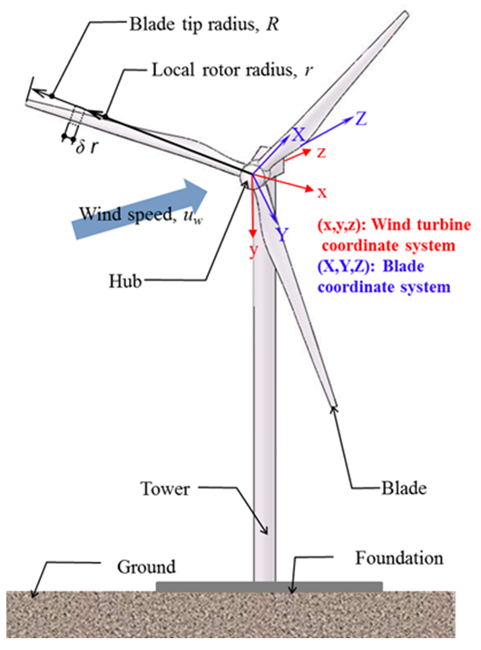 | Figure 1. Schematic of a typical HAWT |
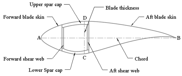 | Figure 2. Schematic of cross-section of the blade |
2. Blade Description
- The overall geometry including airfoil construction and material selections are presented in the following sections. The blade of our 8MW wind turbine (herein referred to as SW45) has a blade tip radius of 80 m and is positioned at a 140 m hub-height [21]. The composite layers (thickness-orientation-material) solely reflect our damage tolerant design efforts with target weight reduction.
2.1. Geometry Specifics
- The full blade geometry is represented in SolidWorks as shown in Figure 3. Although practical wind turbine blades are pre-twisted along the rotor radius, their pre-twist angle distribution is neglected for simplicity in the present model. The thick-airfoil family (NREL S816, S817, S818) is employed for the blade because of its excellent aerodynamic performance [8].
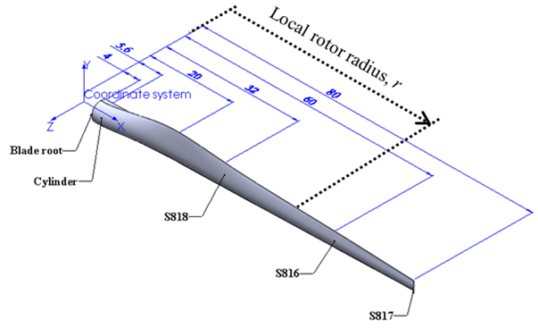 | Figure 3. Dimensions of the 80 m blade |
2.2. Composite Layup
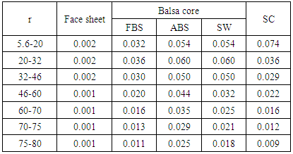
- The root section (4 m < r < 5.6 m) of the blade consists of GF fabric layers. Since metallic bolts with a large diameter are installed into the blade root connected to the hub, this root section usually experiences high stresses which are mitigated with the selection of 40 mm thick laminate. In the airfoil section (5.6 m < r < 80 m), sandwich constructions of GF face sheets with balsa core are employed in the forward/aft blade skin (FBS/ABS) and shear web (SW). The face sheet of the skin is GF fabric layer, and the face in the web is laminated with GF fabric and ±45° UD-GF layers. The spar cap (SC) laminate is composed of 15% CF fabric and 85% UD-GF layers by volume. The full composite lay-up is presented in [4]. Properties of both the skin and spar cap laminates are assigned to the skin between the forward and aft shear web as depicted in Figure 2 creating the asymmetric section stiffness matrix.The laminate thickness in the airfoil section is determined as a function of the airfoil chord length as summarized in Table 1. The thickness of the spar cap laminate and balsa core is assigned as a step function to incorporate a gradual taper in laminate thickness.
|
2.3. Tip Sectional Profile
- A 5m tip sectional blade (TSB5M blade) is extracted from the full SW45 blade to simulate bird impact studies. All geometries and laminate details used in the sectional blade are the same as those located between r = 75 m and r = 80 m of the SW45 blade.
3. Soft Body Impact Representation
3.1. Constitutive Model
- An equation of state (EOS) material model is adopted as an approximation for the constitutive model of a bird (soft body impactor). In this linear model, pressure is obtained from Equation (1) which represents the coupling of pressure and internal energy [22]:
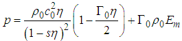 | (1) |
 | (2) |
 | (3) |
 | (4) |
3.2. Representative Bird Geometry/Material
- Since the irregular shape of a bird poses difficulties in impact problems, a cylinder composed of gelatin with hemispherical ends is selected for its representation [17-20]. The aspect ratio of 2, defined as the length (0.238m) of the cylinder to its diameter (0.119m), is adopted to provide a realistic impact pressure profile [23, 24]. The density of gelatin is 911 kg/m3, resulting in a bird mass of 2.0 kg approximately. The properties of gelatin used in the simulations are as follows: c0 = 1.4829×10³ m/s, s = 2.0367, Γ0 = 0, ηv = 4×10⁻³ Ns/m2 [20].
4. Damage and Failure Modes
- Materials with reversible behavior are described by generalized Hooke’s law. Hashin damage initiation criteria and energy-based damage evolution law are utilized to track various damage modes and mechanisms of composite materials while von Mises yield criteria is selected for isotropic materials.
4.1. Progressive Damage in Fiber-Reinforced Composites
- Hashin damage initiation criteria for the composites identify four different damage modes: fiber tension, fiber compression, matrix tension, and matrix compression, as presented in Equations (5) – (8). Damage initiation is detected when the initiation criteria reaches the value of 1.If
 fiber tension mode:
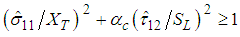 | (5) |
 fiber compression mode:
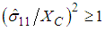 | (6) |
 matrix tension mode:
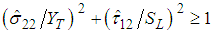 | (7) |
 matrix compression mode:
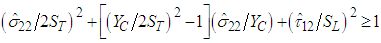 | (8) |
 | (9) |
4.2. Shear Failure in Isotropic Materials
- The shear failure is described with a simple failure criterion that is suitable for dynamic problems and is based on von Mises stress and equivalent plastic strain, as presented in Equations (10) and (11), respectively [22]. Material yielding starts when von Mises stress reaches the allowable strength of isotropic materials. Then, it is assumed that failure occurs when the equivalent plastic strain corresponds to the failure strain of isotropic materials.
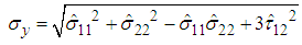 | (10) |
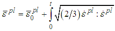 | (11) |
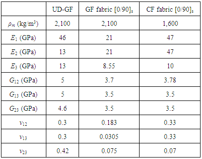
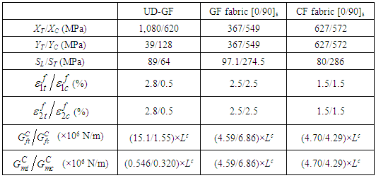
4.3. Material Properties and Allowables
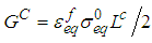
- The materials used in the blade are balsa wood, UD-GF, GF fabric, and CF fabric. The balsa wood which follows an elastic-perfectly plastic behavior in the simulations has the Young’s modulus of 4.1 GPa, Poisson's ratio of 0.3, yield strength of 5.4 MPa, failure strain of 0.8, and density of 155 kg/m3 [12, 28].The homogenized elastic properties of the composite materials are presented in Table 2, and their allowable strength and ultimate strain used to calculate energy dissipation of the composites are presented in Table 3 [29-31]. From Equation (9), the energy dissipation is obtained as a factor of the characteristic length and is presented in Table 3. While von Mises yield criterion is utilized for the balsa wood, Hashin damage model is utilized for the composite materials.
|
|
5. Element and Mesh Selection
- The blade is represented with Lagrangian shell elements that follow the mid-plane shell formulation to avoid the influence of their torsional response [32]. The SW45 blade model with Lagrangian elements is created in HyperMesh, and the mesh size of 0.15 m is employed, generating 41,368 elements. The blade being subjected to aerodynamic loads is analyzed in Abaqus/Standard.The bird impact problems are analyzed in Abaqus/Explicit. The mesh sizes of 0.02 m and 0.01 m are employed for Lagrangian and Eulerian elements, respectively, determined based on the study for the optimal ratio of Lagrangian to Eulerian elements [4]. The TSB5M blade is modeled with Lagrangian elements and contains 64,500 elements while 1,200,000 Eulerian elements are used to define the domain that contains the bird.
5.1. Lagrangian Description
- 3D linear conventional shell elements are appropriate since the blade thickness is significantly smaller than any other global in-plane dimensions such as the blade tip radius or chord length. Accordingly, the blade is represented with S3R/S4R shell elements, which are suitable for nonlinear geometrical analyses. S3R and S4R are a 3-node, trilateral, and 4-node, quadrilateral, stress/displacement, shell element, respectively. These elements have three displacement and three rotational degrees of freedom (DOF) and allow finite strain, arbitrarily large rotations, and transverse shear deformation [22].
5.2. Eulerian Description
- Eulerian elements represent stationary rectangular grids and allow a material to flow through the elements and to interact with Lagrangian element structure. Eulerian elements overcome numerical difficulties associated with excessive element distortion. The element geometry is not conformed to the boundary of Eulerian materials at any time during analysis. Thus, materials are assigned to Eulerian elements by means of volume fraction. 3D Eulerian elements (EC3D8R) in Abaqus/Explicit are adopted in the models. EC3D8R is an 8-node linear brick which accommodates multi-material definition and reduced integration with hourglass control. Note that the nodes of Eulerian elements are independent from Lagrangian S3R/S4R shell elements [22].
6. Loading Conditions
6.1. Lift and Drag Forces
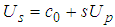
- Aerodynamic loads such as lift and drag forces are dependent on wind speed. For large-scale HAWTs, their maximum values usually occur at nominal wind speed (10-12 m/s). Lift and drag forces of an infinitesimal blade element are calculated using two-dimensional airfoil characteristics, disregarding the velocity along the rotor radius and three-dimensional effects. When the X-axis of the blade is aligned with the x-axis of the wind turbine (Figure 1), lift and drag forces for the rotating blade with an angle of attack are generated. The contribution of lift forces along the y-axis enables the blade to rotate while the decomposed component of drag forces along the y-axis acts on the blade to resist its rotation. Resultant relative wind velocity for the rotating blade is represented by Equation (12) [33]. Note that the wind speed is aligned to the z-axis of the wind turbine.
 | (12) |
 | (13) |
 | (14) |
 | (15) |
 | (16a) |
 | (16b) |
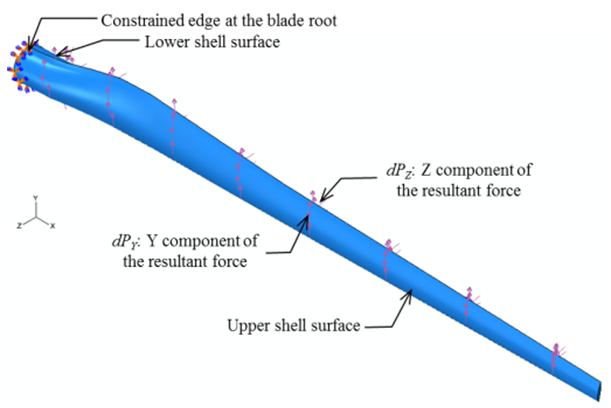 | Figure 4. Boundary conditions for static analyses in the blade |
6.2. Bird Impact
- The CEL approach is employed to simulate the blade-bird strike in Abaqus/Explicit. The Lagrangian target structure for a bird impactor is the 5m tip section of the 80m blade while the 2kg gelation bird is considered as a soft body and modeled with Eulerian elements (EC3D8R). Due to the fixed Eulerian mesh, the boundary of the bird is recomputed in each time increment as it flows through the mesh. Accordingly, gelatin is assigned to Eulerian elements by means of Eulerian volume fraction (EVF) that represents the ratio by which each Eulerian element is filled. Volume fraction of 0 indicates that the elements are not filled at all (i.e., they constitute a void); on the contrary the volume fraction of 1 states that the elements are completely filled with gelatin as seen in Figure 5 [22]. Thus, the bird is represented inside the Eulerian domain with a combination of fully and partially filled elements surrounded by void regions. Direct and oblique impact scenarios are considered, and the impact location is at r = 77.5 m. No initial displacements and stresses are applied to the target structure. A general contact algorithm, which automatically detects which surfaces and edges come into contact, with a penalty method and frictionless surface is employed in the simulations [19, 35].For the direct and oblique impact scenarios, the edges of the blade at r = 75 m are fully constrained, and a time period of 0.01s is considered. For the event of the direct impact, the 2kg bird is assumed to have a translational velocity of 81.4 m/s, and the impact point is the leading edge. This initial velocity is prescribed along the blade Y-axis in the Eulerian domain and is representative of the rated velocity of the rotating blade at the impact point.For the oblique impact, the bird is initially located at r = 77.5 m at an impact angle of 30° to the lower forward blade skin as seen in Figure 5. The initial velocity along the blade Y- and Z-axis is assigned as 70.5 m/s and 40.7 m/s, respectively, leading to 81.4 m/s of resultant velocity.
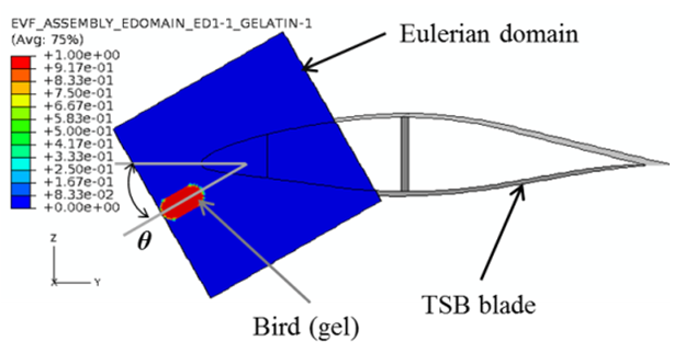 | Figure 5. The bird described by EVF on the cross-sectional view at r = 77.5 m for the direct impact (θ = 0˚) and oblique impact (θ = 30˚) |
7. Results and Discussion
- Herein we present results for the 80 m blade (SW45) which is subjected to lift and drag force and for the 5 m tip sectional blade (TSB5M ) subjected to direct as well as oblique impact.
7.1. Deformation
7.1.1. Tip Displacements due to Aerodynamic Load
- The tip displacements for SW45 are presented at the loads corresponding to wind velocity of uw = 8.72 m/s where the von Mises stress of the balsa core reaches its allowable strength. Thus, it is regarded as core damage.At the onset of the core damage, the U3 tip displacements are much larger than the other displacement components. The blade undergoes U3 tip displacement of 4.96 m, corresponding to 6.2% of the blade tip radius.
7.1.2. Direct Impact: Deformed Shape
- The U2 displacement of the blade at 0.0025s and 0.01s during direct impact is presented in Figure 6 where the maximum values at the impact site are 6.61×10⁻⁴ m and 2.50×10⁻⁴ m, respectively. These displacements are rather small and remain localized at the impact site. As the impact forces are released, the blade starts fluctuating locally and elastic deformation recovery causes the decrease in U2 displacements from 0.0025s to 0.01s.
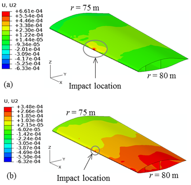 | Figure 6. Global U2 displacement of the 5m tip sectional blade: (a) 0.0025s, and (b) 0.01s |
7.1.3. Oblique Impact: Deformed Shape
- As shown in Figure 7(a), the event of the oblique impact starts at 0.002s when the lower forward blade skin (FBS) locally deflects inward. The deformed shape of the lower FBS on the cutaway view at r = 77.5 m is changed from an arc to a triangle. As shown in Figure 7, the maximum magnitude of the displacements is 0.053 m at 0.006s. The oblique impact does not cause any contact between the upper and lower FBSs. Since the lower FBS toward the skin/spar cap (Point B) is adjacent to the stiff spar cap and shear web, the displacement at Point B is lower than at Point A. After 0.006s, local fluctuation and elastic deformation recovery lead to a decrease in the magnitude of the displacements.
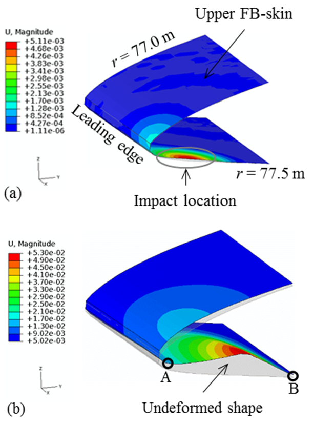 | Figure 7. The magnitude of the displacements of the FBS (77 m < r < 77.5 m) in TSB5M: (a) 0.002s, and (b) 0.006s |
7.2. Motional State of the Bird during Direct Impact
- The EVF contour of the Eulerian domain in the case of the direct impact is presented in Figure 8 to describe the motion of the bird (gel flow). Note that the unfilled elements (i.e., the EVF value of zero) are deleted in the Eulerian domain of Figure 8 for better visualization. First, the gel contacts the leading edge of the blade and starts flowing in two directions (i.e., over the upper and lower blade skin) forming a parabola with increasing time. The contact area between the blade and the gel is rather small around the leading edge, and the gel is split by the sharp form of the airfoil. This configuration helps to reduce the impact forces and thus diminishes the blade deformation.
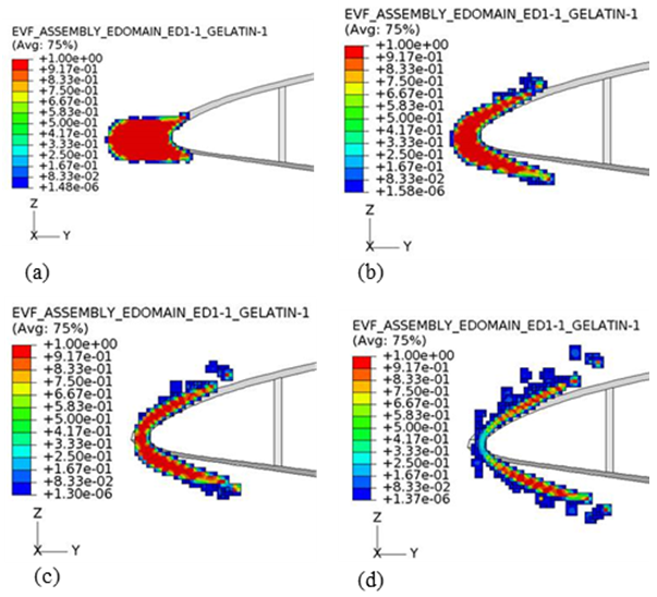 | Figure 8. Motional states of the gel’s EVF on the cross-sectional view at r = 77.5 m: (a) 0.001s, (b) 0.0025s, (c) 0.003s, and (d) 0.004s |
7.3. Stress Fields and Damage Mechanisms in SW45 Blade
- The distance of the outer layer from the centroid of the blade cross-section is greater than that of the inner layer. Also, thickness of the layers is much smaller compared to the distance from the centroid creating higher section modulus in the outer layer than the inner layer. Thus, higher stresses appear in the outermost layer.S11 stresses in the outermost GF fabric layer of the upper blade skin (46 m < r < 80 m) for SW45 blade at uw = 12 m/s are presented in Figure 9. The highest compressive stress magnitude of 94.5 MPa occurs in the skin/spar cap around r = 70 m as seen in Figure 9. However, this value is significantly less than the allowable strength (XC =549 MPa). Flipping in the sign of S11 stress in the skin/spar cap located at 60 m < r < 75 m as seen in Figure 9 indicates presence of warping. Thus, the tensile stresses are seen inside the warp, and the compressive stresses are experienced in the skin/spar cap region outside the warp. This is attributed to the absence of balsa core, as well as insufficient reinforcement by the spar cap in this configuration.
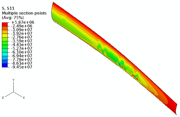 | Figure 9. S11 stress contour in the outermost GF fabric layer of the upper blade skin (46 m < r < 80 m) for SW45 at uw =12 m/s |
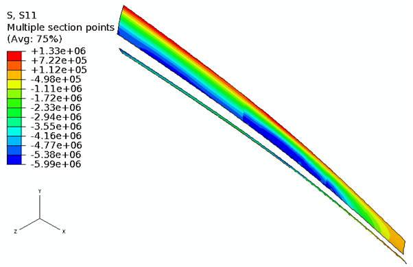 | Figure 10. S11 stress contour in the balsa core of the upper blade skin (46 m < r < 80 m) for SW45 at uw =12 m/s |
7.3.1. Core Damage
- Although balsa cores are used to prevent local buckling mode, yielding of the core starts at uw = 8.72 m/s. The von Mises stresses in the core of the skin and web at uw = 12 m/s are presented in Figure 11.
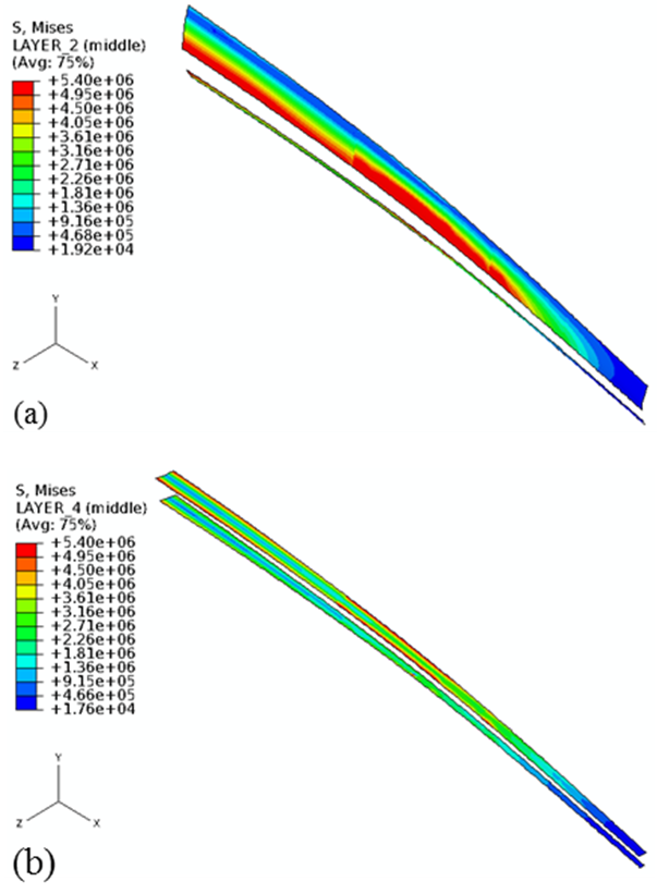 | Figure 11. Von Mises stress contour in the balsa core for SW45 at uw =12 m/s: (a) the upper blade skin (46 m < r < 80 m), and (b) the web (46 m < r < 80 m) |
7.3.2. Damage due to Direct Impact
- The structural components of the hybrid blade (sandwich skin, shear web, and spar cap) of the 5m blade are much more rigid than the soft body of the bird. Even though overall small deformations are observed at the time of impact, von Mises stress in the balsa core of the forward blade skin reaches its allowable strength of 5.4 MPa at the impact site. Thus, yielding of the balsa occurs at 0.0005s, generating an equivalent plastic strain of 0.01 at 0.006s as shown in Figure 12. Afterward, the plastic strain does not increase since the impact energy has already been dissipated at the leading edge. Throughout the event, the balsa core in the shear web remains below its allowance. Furthermore, no damage initiation and progression caused by the direct impact are observed in any of the composite layers.
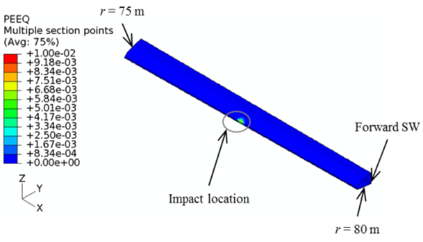 | Figure 12. Equivalent plastic strain in the balsa of the FBS and SW at 0.006s |
7.3.3. Damage due to Oblique Impact
- In the event of the oblique impact, the bird, initially located at r = 77.5 m, contacts the lower FBS. The lower FBS bulges out in the positive Z-axis, creating the highest compressive S22 stress (300 MPa) at 0.004s as shown in Figure 13. The highest tensile stress is 247 MPa near the shared edge at 0.004s. Matrix tensile damage is observed over a region that is 0.42 m in length with a surface area of 7.9×10⁻³ m2 as depicted in Figure 13(a). Note that the tensile stress that occurs at the center of the impact region at 0.005s causes matrix tension damage at 0.006s as seen in Figure 13(b). Consequently, the fabric layer located in this failure region is much weaker and softer than UD-GF layer and susceptible to extremely high strains in the 2-direction.
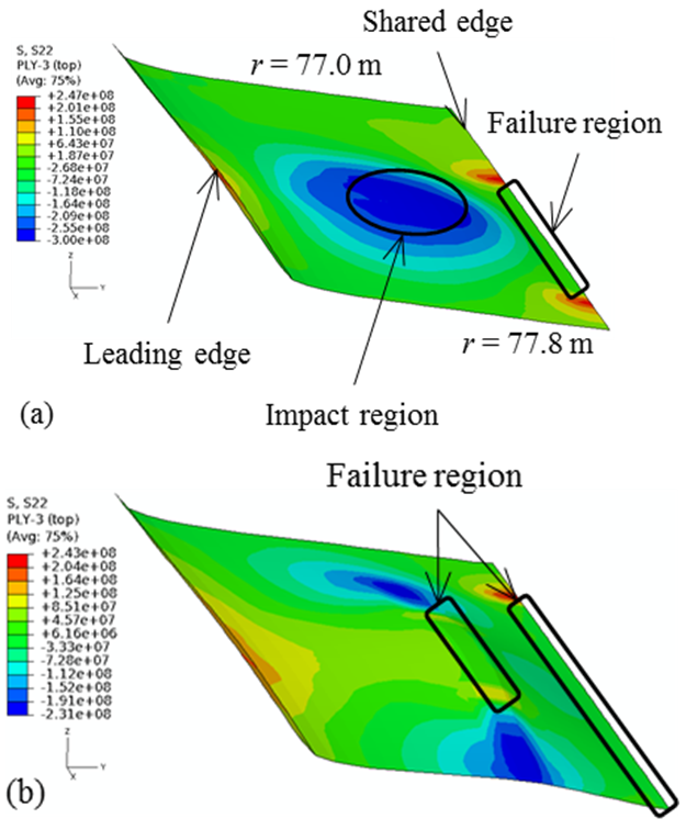 | Figure 13. S22 stress in the outermost GF fabric of the lower FBS (77 m < r < 77.8 m): (a) 0.004s, and (b) 0.006s |
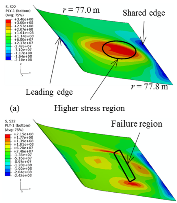 | Figure 14. S22 stress in the innermost GF fabric of the lower FBS (77 m < r < 77.8 m): (a) 0.004s, and (b) 0.0045s |
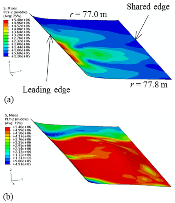 | Figure 15. Von Mises stress in the balsa of the lower FBS (77 m < r < 77.8 m): (a) 0.002s, and (b) 0.005s. |
8. Conclusions
- In the 80 m full-length blade model, the largest displacements occurred along the blade Z-axis where the resultant aerodynamic forces were the largest. The largest U3 tip displacement was 6.2% of the blade tip radius when yielding in the balsa core ensued under the loads associated with wind speed, uw = 8.72 m/s. Since Hashin damage initiation criteria in all composite layers were below the damage state value of 1, the GF and CF layers of the blade root, skin, shear web, and spar cap were not damaged. The S11 stress in the GF fabric face of the sandwich skin was several times higher than that in the balsa core since the core was stiffer and weaker compared with the GF face materials. Furthermore, flipping the sign of S11 stress in the upper skin/spar cap (60 m < r < 75 m) indicated the formation of a warp which potentially could lead to wrinkling. Thus, the blade configuration provided sufficient damage tolerance below the loads associated with uw = 8.72 m/s.The 2kg bird upon the direct impact with the 5m tip section of the 80m blade caused a small U2 displacement (up to 6.61×10⁻⁴ m). This impact scenario created minor and localized deformation in the blade since the contact area between the blade and bird remained small due to the sharp airfoil shape at the leading edge to reduce the transfer of impact forces to the blade effectively. However, the balsa core in the forward blade skin exceeded its yield strength. Stresses in composite layers were much smaller than their allowable strength. Thus, no damage initiation in the composite layers was found during direct impact.In the oblique impact scenario, the balsa core exceeded its yield near the leading edge at 0.002s. Matrix tensile damage initiation and progression in the GF fabric layer was observed at the following locations: at outermost layer at the shared edge with shear web and skin/spar at 0.004s, at the innermost layer at the impact location at 0.0045s, and at the outermost layer at the impact location at 0.006s. However, the bird did not penetrate the lower forward blade skin. While the direct impact configuration effectively reduced the transfer of impact forces to the blade, the oblique impact forces were dissipated on the impact site where tensile damage/failure mode was observed.
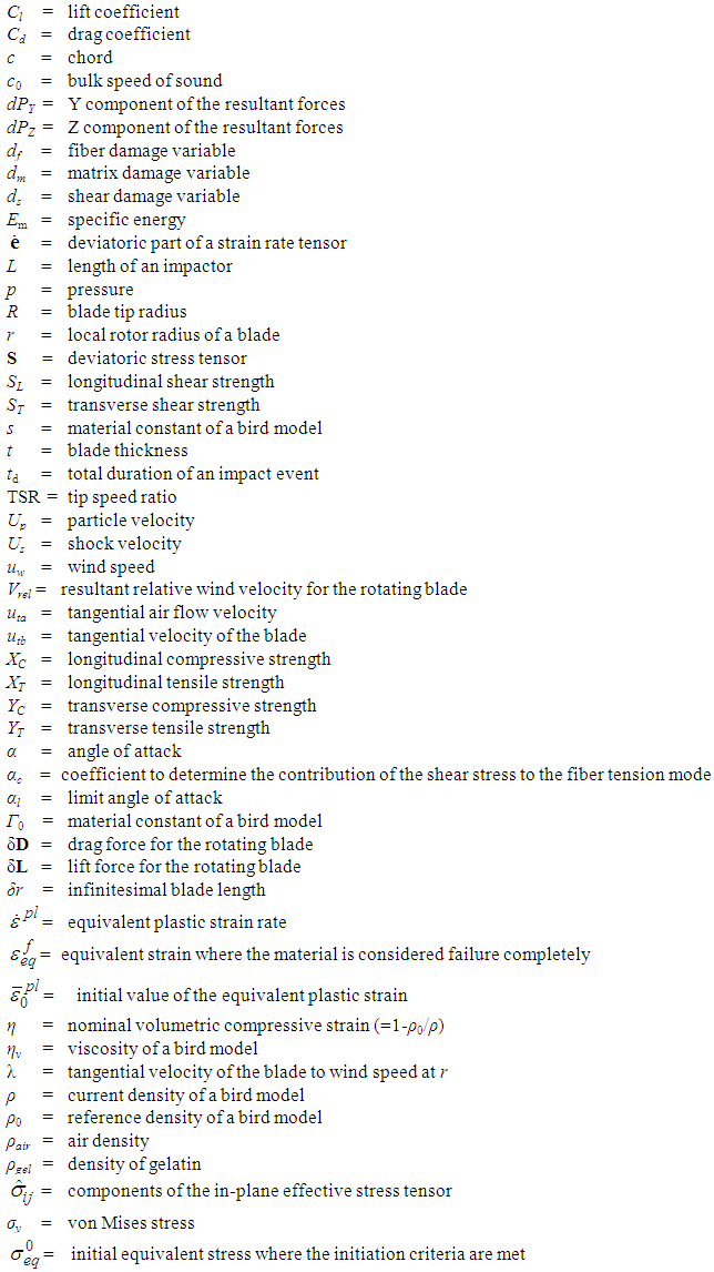
Nomenclature