Wei-Qian Jian1, Han Guo1, Wu-Sung Yao1, PO-Chi Hsu2
1Department of Mechanical and Automation Engineering, National Kaohsiung First University of Science and Technology, Taiwan
2Earth Energy International Technology Co., Ltd, Taiwan
Correspondence to: Wu-Sung Yao, Department of Mechanical and Automation Engineering, National Kaohsiung First University of Science and Technology, Taiwan.
| Email: |  |
Copyright © 2016 Scientific & Academic Publishing. All Rights Reserved.
This work is licensed under the Creative Commons Attribution International License (CC BY).
http://creativecommons.org/licenses/by/4.0/

Abstract
In this paper, a 1200W gravity-driven electromagnetic energy harvester with a designed mechanical flywheel is proposed, where the mechanical flywheel is used to generate gravity energy. The placement and the electric current input of the electromagnet are designed to achieve the stable rotation speed of the flywheel. Therefore, in this study, the theoretical relation between the electrical power input of the electromagnet and the flywheel’s rotation speed is constructed. The electromagnetic force acts on mechanical flywheel is deduced by virtual work method for a single-pole electromagnet and the output power for the harvester is derived by the theoretical study. The physical characteristic of the electromagnetic energy harvester is analyzed, and an ANSYS finite element analysis simulation is used to determine the appropriate position of the electromagnet with the magnetic flux lines and density. Design parameters such as input frequency, maximum displacement, number of coil turns, and load resistance is analyzed. The advantages include improved reliability, efficiency, and steadier output power. Harvester prototype testing results illustrate features and benefits of the gravity-driven flywheel based harvester, showing reduction of continual system loading, regulation of generator speed, and capability for continuous power generation.
Keywords:
Electromagnet, Gravity, Energy harvester, Flywheel, Virtual work method
Cite this paper: Wei-Qian Jian, Han Guo, Wu-Sung Yao, PO-Chi Hsu, Design of Gravity-Driven Electromagnetic Energy Harvester, Journal of Mechanical Engineering and Automation, Vol. 6 No. 3, 2016, pp. 71-74. doi: 10.5923/j.jmea.20160603.05.
1. Introduction
In generally, charge actions are influenced by electric field or magnetic field in Electromagnetism, practically, a force from magnetic field acts on objects is rarely to be explored, since more designed parameters should be considered such as geometry, length of air gap, strength of magnetic field, permeability coefficient of material etc. Therefore, it is difficult to obtain a correct mathematic model and calculate electromagnetic force acting on objects, which dynamic characteristic is nonlinear and time-variant. In order to determine the electromagnetic force acting on objects, Maxwell stress tensor (MST) or virtual work method often utilized in exist literatures. Ref. [1] calculates the electromagnetic force acts on current conductor by Maxwell stress tensor. Ref. [2] introduces complete concept of Maxwell stress tensor and virtual work method. Ref. [3] proposed the virtual work method to estimate electromagnetic force acting on non-current conductor. In this paper, the electromagnetic force by virtual work method is calculated. An ideal model for estimating electromagnetic force is constructed by ANSYS finite element analysis simulation and the magnetic flux density is demonstrated by Gauss meter. The capabilities of electromagnet are demonstrated by employing a rotary encoder to measure the dynamic data of harvester and filter out the noise by using least square method (LSM) [4] in order to improve the performance.It is important to confirm the relation from the placement and the electric current input of the electromagnet to the flywheel’s rotation speed to improve the working efficiency of the harvester. Flywheel should be operated in rated speed, and variable speed will produce a negative impact and leads to damage of harvester, thus both of the placement and the electric current input of the electromagnet have to be considered, which is simulated by ANSYS.
2. Method
2.1. Design of Mechanical Flywheel
The capabilities of mechanical flywheel is used to generate gravity energy to drive generator and to accelerate the rotation speed of the generator with 12: 1 gear ratio. Figure 1 shows the designed mechanical structure of a 1200W energy harvester with a mechanical flywheel, where the weighs of the flywheel is about 90 kg and constructed by medium carbon steel. The operation is to rise the mechanical flywheel to highest place and drop it free down to maintain stable rotating with 1200rpm of the generator.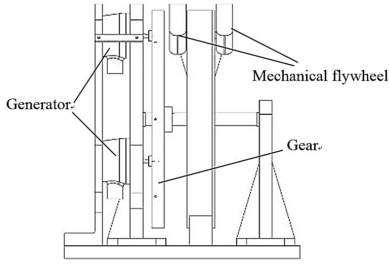 | Figure 1. Design mechanical structure of the generator |
2.2. Design and Analysis of the Electromagnet
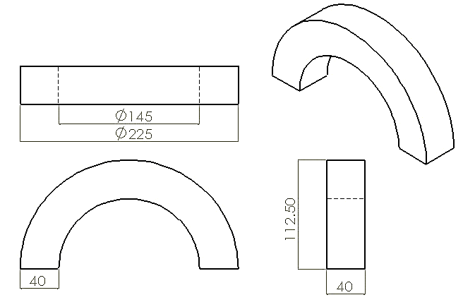
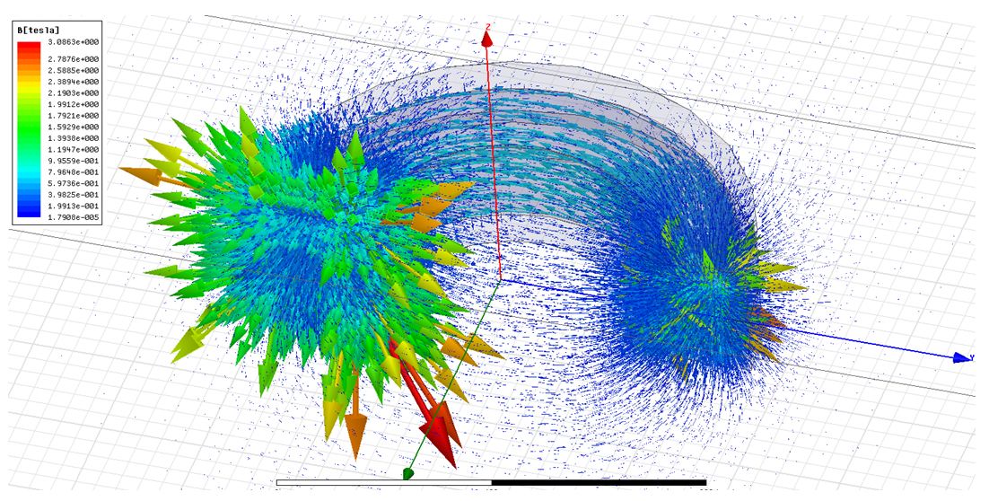
The design parameters of the electromagnet are included of current input, number of turns, permeability of iron core, which provide magnetic motive force. Figure 2 shows the B-H curve of the iron core (30RG130), it has enough saturation area of magnetic flux density to accommodate current magnetization. According to the ratio of wire outer diameter and wound area of the iron core as shown in Fig. 3, an appropriate magnetomotive force of electromagnet is given as 13000 Ampere turns.The electromagnetic simulation result is shown in figure 4, it obvious to illustrate the flux lines versus density and its magnitude of electromagnet.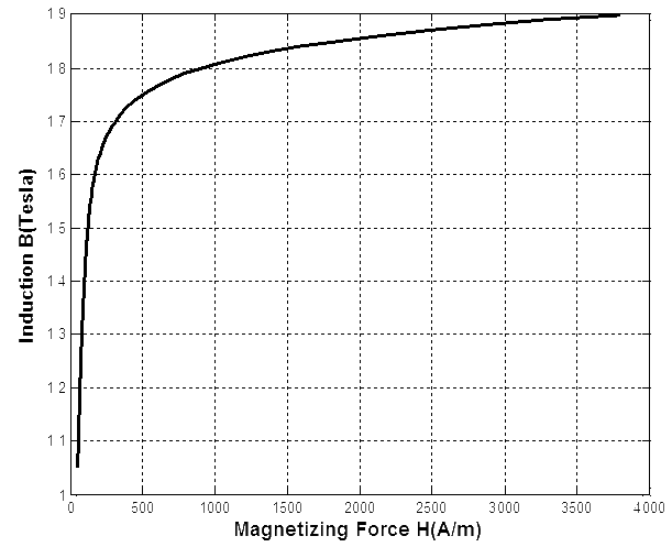 | Figure 2. B-H curve of the iron core |
 | Figure 3. Sizes of the iron core |
 | Figure 4. Electromagnetic simulation result |
2.3. Computing the Electromagnetic Force by Virtual Work Method
The voltage equation for the electromagnet winding is written as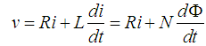 | (1) |
where v is voltage connected to winding terminals, R is the resistance of the winding, Φ is the winding flux, L is the self-inductance of the winding, and N is the number of turns in winding. The power of the electromagnet in winding is given as 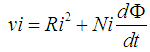 | (2) |
and the energy equation can be obtained as 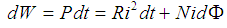 | (3) |
where NidΦ is defined as the stored magnetic field energy and Ri2 dt turns into heats. In electromechanical systems, the electrical energy can be stored mainly in magnetic field; therefore, the energy transfer can be represented as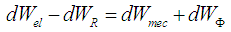 | (4) |
where dWel is the differential electrical energy input, dWR is the differential energy losses, dWmec is the differential mechanical output and dWΦ is the differential change of magnetic stored energy. The electrical energy minus losses is equal to the sum of the change of work done by the system and the change of stored magnetic energy. In other words, the electrical energy does not work and the displacement happened by mechanical work should be reduced by the magnetic field energy. Assume that the magnetic flux linkage in air gap is constant, and the stored magnetic field energy can be given as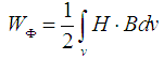 | (5) |
By H=B/μ, we can obtain then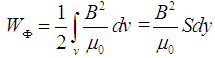 | (6) |
where S is the cross-sectional area of electromagnet and dy is virtual displacement with perpendicular to the cross-sectional area of electromagnet. (6) shows the stored magnetic field energy in air gap. Since the flux linkage is constant and the mechanical work is equal to FΦdy, the electromagnetic force is obtained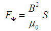 | (7) |
where B is magnetic flux density in air gap, consisting the relative permeability and geometry of iron core versus flywheel. With the magnetic flux density B, the electromagnetic force can be determined by (7). Figure 5 shows the magnetic flux density in air gap is measured by Gauss meter, and substituted into (7) to obtain the electromagnetic force as 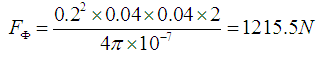 To withstand the flywheel under 3mm air gap, the electromagnetic force should be over 90kg. Figure 6 is the proportional relationship between magnetomotive force and electromagnetic force from simulation. The electromagnet of Ampere turns is 13000At, which is greater than 11000At. In fact, 1215.5N from virtual work method can be correspond to Fig. 6.
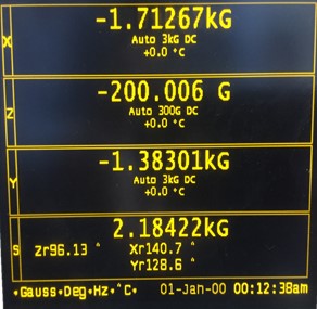 | Figure 5. Measurement results |
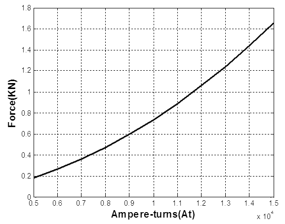 | Figure 6. Relation of force and Ampere-turns |
3. Experimental Setup and Result
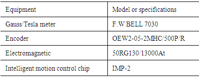
Figure 7 shows the prototyped energy harvester, where an experimental specifications is listed in Table 1. The electromagnet is used to provide a tangential component force and leads to an appropriate displacement of mechanical flywheel.Table 1. Experiment specifications list
 |
| |
|
There is an accurate measurement to illustrate the experiment setup being feasible and the performance of electromagnet is measured by encoder and Gauss meter as shown as Fig. 7. The working time of electromagnet can be determined by the position of the mechanical flywheel. Note that the electromagnet is started up with mechanical flywheel rotating at 300 degrees, and turned off with mechanical flywheel swing over 360 degrees. The electromagnet can provide a force with appropriate displacement of mechanical flywheel in first lap as shown in Fig. 8. 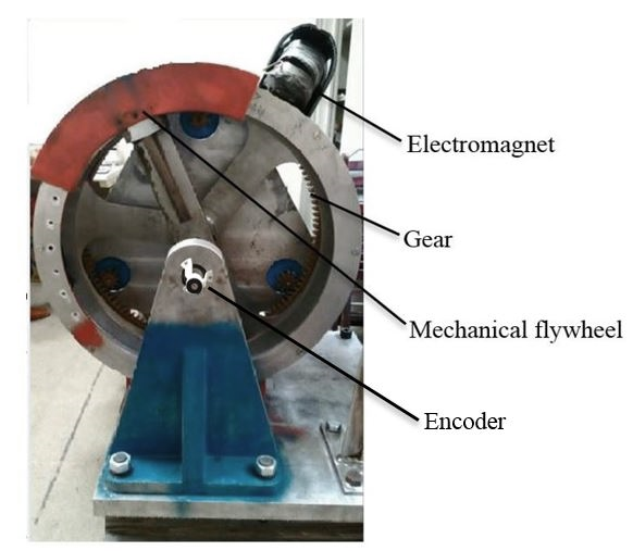 | Figure 7. Prototype of the energy harvester |
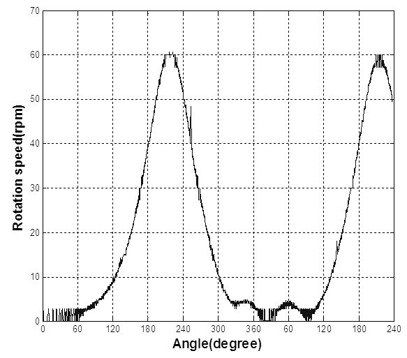 | Figure 8. Experimental result |
4. Conclusions
This paper proposes a methodology for the design and performance of an electromagnet applied to gravity-driven energy harvester. It combines an analytical field model, a mathematical derivation solution of the virtual work applied to electromagnet, and a dynamic gravity-driven analysis model. An illustrated example is given to verify the working efficiency of the proposed generator.
References
| [1] | Stanley Humphries. (2012). Tutorial: Theory and applications of the Maxwell stress tensor [Online]. Available: http://www.fieldp.com. |
| [2] | P.L. Juha, J. Tapani, and H. Valeria, Design of Rotating Electrical Machines, 2nd ed. John Wiley & Sons, 2013, ch.1. |
| [3] | W.F. Chen and X.Q. Hu, “Virtual Displacement Method Applied to Analysis of Electromagnetic Field Strength,” Journal of Chongqing Normal University (Natural Science), Vol. 27, No. 5, pp. 62-65, Sep. 2010. |
| [4] | C.H. Liao. 2004. Study on Velocity and Acceleration Estimation from Discrete-Time Position Data. Master’s dissertation. National Cheng Kung University, Taiwan. |

 Abstract
 Reference
 Full-Text PDF
 Full-text HTML